Table of Contents
Advertisement
OPERATORS' MANUAL
M250 DOUBLE-PULSE SYNERGIC
MULTI-MIG WELDING SYSTEM
IMPORTANT: Read this Owner's Manual Completely before attempting to use this
equipment. Save this manual and keep it handy for quick reference. Pay particular
attention to the safety instructions we have provided for your protection. Contact your
distributor if you do not fully understand this manual.
Advertisement
Table of Contents
Troubleshooting

Summary of Contents for H&S HSM250
- Page 1 OPERATORS’ MANUAL M250 DOUBLE-PULSE SYNERGIC MULTI-MIG WELDING SYSTEM IMPORTANT: Read this Owner’s Manual Completely before attempting to use this equipment. Save this manual and keep it handy for quick reference. Pay particular attention to the safety instructions we have provided for your protection. Contact your distributor if you do not fully understand this manual.
-
Page 2: Table Of Contents
CONTENT CONTENT §1 Safety ......................1 §1.1 Symbols Explanation ................... 1 §1.2 Machine Operating warnings! ..............1 §1.3 EMC device classification ................8 §1.4 EMC measure ....................9 §1.5 Warning label ..................... 10 §2 Overview ....................11 §2.1 Features ....................... 11 §2.2 Technical Data .................... - Page 3 CONTENT §4.3.3 Wire Installation and Set-Up Guide ..............44 §4.3.4 Set up for MIG Welding- Aluminum or Silicone Bronze Wire ......46 §4.3.5 MIG Torch Liner Installation ................46 §4.3.6 MIG Torch Liner Types and Information ............48 §4.3.7 Torch & Wire Feed Set-Up for Aluminum Wire ..........49 §4.3.8 Set-Up Installation for Spool Gun ..............
-
Page 4: Safety
SAFETY §1 Safety Welding and cutting equipment can be dangerous to both the operator and people in or near the surrounding working area, if the equipment is not correctly operated. Equipment must only be used under the strict and comprehensive observance of all relevant safety regulations. Read and understand this instruction manual carefully before the installation and operation of this equipment. - Page 5 SAFETY equipment according to §7 because of the DC voltage existing in the electrolytic capacitors at the output of the power supply! ELECTRIC SHOCK CAN KILL. Touching live electrical parts can cause fatal shocks or severe burns. The electrode and work circuit is electrically live whenever the output is on. The input power circuit and internal machine circuits are also live when power is on.
- Page 6 SAFETY machine in good, safe operating condition. Replace damaged insulation. Never dip the electrode in water for cooling. Never simultaneously touch electrically “hot” parts of electrode holders connected to two welders because voltage between the two can be the total of the open circuit voltage of both welders.
- Page 7 SAFETY Read and understand the manufacturer’s instructions for this equipment and the consumables to be used, including the material safety data sheet and follow your employer’s safety practices. ARCRAYS: Harmful to people’s eyes and skin. Arc rays from the welding process produce intense visible and invisible ultraviolet and infrared rays that can burn eyes and skin.
- Page 8 SAFETY and do not start engine until fumes have been eliminated. WELDING SPARKS can cause fire or explosion. Welding on closed containers, such as tanks, drums, or pipes, can cause them to explode. Flying sparks from the welding arc, hot work piece, and hot equipment can cause fires and burns.
- Page 9 SAFETY welding area. Connect the work cable to the work as close to the welding area as practical. Work cables connected to the building framework or other locations away from the welding area increase the possibility of the welding current passing through lifting chains, crane cables or other alternate circuits.
- Page 10 SAFETY cylinder can explode. Because gas cylinders are normally part of the welding process, be sure to treat them carefully. CYLINDERS can explode if damaged. Protect gas cylinders from excessive heat, mechanical shocks, physical damage, slag, open flames sparks, and arcs. Insure cylinders are held secure and upright to prevent tipping or falling over.
-
Page 11: Emc Device Classification
SAFETY All cables should be put away and far from the operator. Never coil the power cable around your body. Make sure welding machine and power cable to be far away from the operator as far as possible according to the actual circumstance. ... -
Page 12: Emc Measure
SAFETY Radiation Class B device. It can meet the radiation requirements of residential area and industrial area. It also can be used in residential area which power is supplied by public low voltage circuit. EMC device can be classified by power nameplate or technical data. Hi-zone welding machines belong to Class A. -
Page 13: Warning Label
SAFETY c) Equipotential connection d) Ground connection of work-piece When necessary, use appropriate capacitance to connect the ground. e) Shielding, when necessary Shield the ambient devices Shield the whole welding machine §1.5 Warning label The device with a warning label. Do not remove, destroy or cover this label. -
Page 14: Overview
OVERVIEW §2 Overview §2.1 Features ⚫ New PWM technology and IGBT inverter technology for high efficiency operation. ⚫ Three dedicated wire feed systems for high productivity and no cross contamination. ⚫ MIG/MAG with Pulse Synergic / Dual Pulse Synergic, Manual and Synergic function -Synergic programs for aluminum, mild steel, stainless steel and silicone bronze -JOB mode (Save and call 100 job records) -
Page 15: Technical Data
OVERVIEW §2.2 Technical Data Note: The above parameters are subject to change. §2.3 Brief Introduction The DOUBLE PULSE SYNERGIC (DPS) series of welding machines is a new inverter-based MIG/MMA/TIG Welding machine with Synergic Programs and Dual pulse functions. The MIG function allows you to weld with Gas Shielded wire applications giving excellent, professional welding results. -
Page 16: Duty Cycle And Over-Heat
OVERVIEW includes adjustable up/down slope & pre/post gas control. The stick welding (MMA) capability delivers easy electrode welding with high quality results, including cast Iron, stainless and low hydrogen with hot-start and arc-force adjustment. An additional feature is the spool gun function that allows the simple connection of Spool Gun for the use of thin or softer wires that don’t have the column strength to feed through MIG torches, such as some aluminum and silicone bronze wires. -
Page 17: Working Principle
OVERVIEW §2.5 Working Principle The working principle of DPS series welding machine is shown as the following figure. Single-phase 208-240VAC is rectified into DC, then is converted to medium frequency AC (about 20KHz) by inverter device (IGBT), after reducing voltage by medium transformer (the main transformer) and rectifying by medium frequency rectifier (fast recovery diodes), and fine-tuned by inductance filtering. -
Page 18: Panel Functions & Descriptions
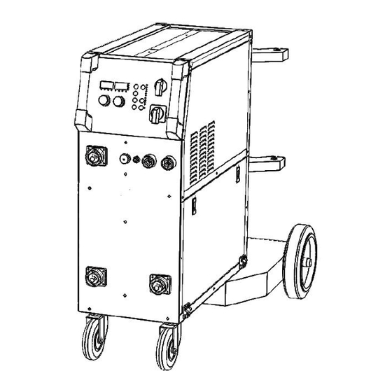
OPERATION §3 Panel Functions & Descriptions §3.1 Machine Layout Description Front and rear panel layout of welding machine 1. MIG torch euro-connectors (3) 2. Main power ON/OFF Switch 3. Torch output “SELECT” switch (0-3) 4. Positive(+) welding power output 5. Negative(-) welding power output 6. -
Page 19: Control Panel Of Welding Machine
OPERATION §3.2 Control panel of welding machine 1. Synergic program indicator. 2. Welding voltage indicator. 3. RH digital multifunction display. 4. Arc length indicator. 5. Inductance indicator. 6. Material thickness indicator. 7. Wire feed indicator. 8. LH digital multifunction display. 9. - Page 20 OPERATION Alarm Indicator (13) Illuminates when the power supply has exceeded duty-cycle and entered an over-temperature condition. The unit will automatically reset once cooled and lamp will go off. JOB program save (16) In the JOB mode, 100 different JOB records can be stored and recalled. When leaving the factory, has no saved JOB programs;...
- Page 21 OPERATION DISPLAY FUNCTION ADJUSTABLE RANGE MODE PRE GAS 0-5S POST GAS 0-10S SLOW FEED TIME 0-10S BURN BACK 0-10 SPOT WELD TIME 0-10S DELTA PULSE CURRENT 0-200A DUAL PULSE FREQUENCY 0.5-3.0Hz DUAL PULSE DUTY 10-90% DUAL PULSE DUAL PULSE BASE CURRENT +10 / -10 ARC LENGTH START CURRENT PERCENT...
- Page 22 OPERATION 4T mode (Latching) Self-Locking Function Gun Switch Gas Supply Wire Feed Output Voltage Output Current End Current conditions Welding conditions S4T mode Transition Time Burnback Time Gun Switch Gas Supply Wire Feed Output Voltage Output Current Welding condition End Current condition Initial condition Spot weld Gun Switch...
- Page 23 OPERATION Program SELECT Indicator (21) Synergic Function The operator simply sets the welding current like MMA or TIG welding and the machine calculates the optimal voltage and wire speed for the material type, wire type and size and shielding gas being used. Obviously other variables such as welding joint type and thickness, air temperature affect the optimal voltage and wire feed setting, so the program provides a voltage fine tuning function for the synergic program selected.
- Page 24 OPERATION ◼ DUAL PULSE FREQUENCY Set pulse frequency, as shown in Figure regulating the value of time T, namely, ripple pattern of density regulation. Higher Hz produces many short ripples with slightly lower penetration. ◼ DUAL PULSE DUTY Set strong pulse time T1 (peak) for penetration and low-frequency cycle T2 ratio (cooling), namely the regulation of the proportion of the ripple pattern on weld puddle surface and resulting depth in groove.
- Page 25 OPERATION MIG Double-Pulse Synergic Function- Front Panel Description 1. Function Select: MIG Double-Pulse Synergic 2. Trigger Select: 2T/4T/S4T/Spot 3. Function Select: refer to§ 4.4 4. Synergic Program Select: refer to§ 4.4 4. Set: Voltage / Arc Length / Inductance 5. Set: Material Thickness / Current / Wire Speed 6.
- Page 26 OPERATION MIG Synergic Function-Front Panel Description 1. Function Select: MIG Synergic 2. Trigger Select: 2T/4T/S4T/Spot 3. Function Select: refer to§ 4.4 4. Synergic Program Select: refer to§ 4.4 4. Set: Voltage / Arc Length / Inductance 5. Set: Material Thickness / Current / Wire Speed 6.
- Page 27 OPERATION TIG Mode - Front Panel Description 1. Display Code Parameter: Down Slope 2. Display Welding Current: Down Slope 3. Welding Current Indicator (Amps) 4. Function Select: TIG (Lift-Arc) 5. Trigger Select: 2T or 4T 6. Parameter Select: Down Slope 7.
-
Page 28: Installation & Operation
OPERATION §4 Installation & Operation §4.1 Installation & Operation for MMA/Stick Electrode Welding §4.1.1 Set-Up Installation (1) Connection of Output Cables: Two sockets are available on this welding machine, One Positive(+) and one Negative (-) polarity, to connect MMA/Electrode holder cable and earth clamp cable. -
Page 29: Mma/Stick Electrode Welding
OPERATION (4) Set the Hot Start and Arc Force as required using the Fx select and setting knobs. (5) Place the electrode into the electrode holder and clamp tight. (6) Strike the electrode against the work piece to create and arc and hold the electrode steady to maintain the arc. -
Page 30: Mma Welding Fundamentals
OPERATION MMA / Stick Electrode •The arc is initiated by momentarily touching the electrode to the base metal. • The melted electrode metal is transferred across the arc into the molten pool and becomes weld metal. • The deposit is covered and protected by slag from the electrode flux coating. Flux Properties ●... - Page 31 OPERATION The size of the electrode generally Average Thickness Max. Recommended depends on the thickness of the section of Material Electrode Diameter being welded, and the thicker the section 1.0-2.0 mm 2.5 mm the larger the electrode required. The 2.0-5.0 mm 3.2 mm maximum size of electrodes that may be 5.0-8.0 mm...
-
Page 32: Installation & Operation For Tig Welding
OPERATION Electrode Angle The angle that the electrode makes with the work is important to ensure a smooth, even transfer of metal. When welding in down hand, fillet, horizontal or overhead the angle of the electrode is generally between 5 and 15 degrees towards the direction of travel. When vertical up welding the angle of the electrode should be between 80 and 90 degrees to the work piece. - Page 33 OPERATION (7) Connect the power cable of welding machine to the electrical outlet. (230VAC, 1Ph) (8) Carefully open the valve of the gas cylinder, set the required gas flow rate. (9) Select TIG function on the front panel. (10) Set torch operation for 2T or 4T: •...
- Page 34 OPERATION (13) Assemble front end parts of the TIG (14) Lay the outside edge of the cup torch, fitting a sharpened tungsten suitable on work piece with the tungsten 1- 2mm for the material to be welded. from the work piece. (15) With a small movement rotate the gas (16) Now rotate the gas cup in the reverse cup forward so that the tungsten electrode...
-
Page 35: Dctig Welding
OPERATION §4.2.2 DCTIG Welding The DC power source uses what is known as DC (direct current) in which the main electrical component, known as electrons, flow in only one direction from the negative terminal (-) to the positive terminal (+). In the DC electrical circuit there is an electrical principle at work which provides that, in a DC circuit, 70% of the energy (heat) is always on the positive side. -
Page 36: Tig Welding Fusion Technique
OPERATION LIFT ARC IGNITION for TIG Welding Lift Arc is a form of arc ignition where the machine has voltage on the electrode to only a few volts, with a current limit of one or two amps (well below the limit that causes metal to transfer and contamination of the weld or electrode). - Page 37 OPERATION TIG Welding with Filler Wire Technique It is necessary in many situations with TIG welding to add a filler wire into the weld pool to build up weld reinforcement and create a strong weld. Once the arc is started the torch tungsten is held in place until a weld pool is created, a circular movement of the tungsten will assist is creating a weld pool of the desired size.
-
Page 38: Tungsten Electrodes
OPERATION §4.2.4 Tungsten Electrodes Tungsten is a rare metallic element used for manufacturing TIG welding electrodes. The TIG process relies on tungsten’s hardness and high-temperature resistance to carry the welding current to the arc. Tungsten has the highest melting point of any metal, 3,410 degrees Celsius. - Page 39 OPERATION Ceriated (Orange) Ceriated tungsten electrodes (AWS classification EWCe-2) contain a minimum of 97.30 percent tungsten and 1.80 to 2.20 percent cerium and are referred to as 2% ceriated. Ceriated tungsten performs best in DC welding at low current settings. They have excellent arc starts at low amperages and become popular in such applications as orbital tube welding, thin sheet metal work.
-
Page 40: Tungsten Preparation
OPERATION Tungsten Electrodes Rating for Welding Currents Tungsten DC Current Amps AC Current Amps AC Current Amps Diameter Torch Negative Un-Balanced Wave Balanced Wave 2% Thoriated 0.8% Zirconiated 0.8% Zirconiated 1.0mm 15-80 15-80 20-60 1.6mm 70-150 70-150 60-120 2.4mm 150-250 140-235 100-180 3.2mm... - Page 41 OPERATION Electrode Shape & Angle The shape of the tungsten electrode tip is an important process variable in precision arc welding. A good selection of tip/flat size will balance the need for several advantages. The bigger the flat, the more likely arc wander will occur and the more difficult it will be to arc start.
-
Page 42: Tig Torch Switch Controls
OPERATION Tungsten Diameter at Constant Current Range Current Range Diameter the Tip - mm Included Angle - Amps Pulsed Amps Degrees 1.0mm .250 05 - 30 05 - 60 1.6mm .500 08 - 50 05 - 100 1.6mm .800 10 - 70 10 - 140 2.4mm .800... -
Page 43: Installation & Operation For Mig Welding
OPERATION §4.3 Installation & Operation for MIG Welding §4.3.1 Set up installation for MIG Welding (Gas shielded wire) Insert the earth cable plug into the Negative (-) socket and twist to tighten. Plug the MIG welding gun into THREE euro-connect sockets on the front panel and tighten locking nut securely. - Page 44 OPERATION (8) Carefully feed the wire over the drive roller into the outlet guide tube, feed through about ½” (150mm) into the torch receptacle. (9) Check that the drive roller size is compatible with the wire diameter, replace the roller if necessary.
-
Page 45: Wire Feed Roller Selection
OPERATION (11) Remove Tip (12) Feed wire manually (WARNING: Be sure to keep torch neck away from your eyes, face or hands as the wire exits the swan neck!) (13) Fit the correct sized contact tip and feed the wire through it, screw the contact tip into the tip holder of the torch neck and nip it up tightly. - Page 46 OPERATION optimum wire feed. Solid Hard Wire - like Steel, Stainless Steel require a drive roller with a “V” shape groove for optimum grip and drive capability. Solid wires can have more tension applied to the wire from the top pressure roller that holds the wire in the groove and the “V” shape groove is more suited for this.
-
Page 47: Wire Installation And Set-Up Guide
OPERATION §4.3.3 Wire Installation and Set-Up Guide The importance of smooth consistent wire feeding during MIG welding cannot be emphasized enough. The correct installation of the wire spool and the wire into the wire feed unit is critical to achieving an even and consistent wire feed. A high percentage of faults with MIG welders emanate from poor set up of the wire into the wire feeder. - Page 48 OPERATION (5) Feed the wire through the drive rollers (6) Lock down the top pressure roller and and into the outlet guide tube of the wire tighten using the tension adjustment knob. (7) Check that the wire passes through the center of the outlet guide tube without touching the sides.
-
Page 49: Set Up For Mig Welding- Aluminum Or Silicone Bronze Wire
OPERATION (9) The weight and speed of the wire spool turning creates an inertia that can cause the spool to run on and the wire loop over the side of the spool and tangle. If this happens increase the pressure on the tension spring inside the spool holder assembly using the tension adjustment screw. - Page 50 OPERATION (3) Carefully pull out and completely remove (4) Carefully unravel the new liner. (5) Carefully feed in the new liner down the torch (6) Fit the liner retaining nut and screw lead all the way to exit the torch neck. only 1/2 way down.
-
Page 51: Mig Torch Liner Types And Information
OPERATION §4.3.6 MIG Torch Liner Types and Information MIG Torch Liners The liner is both one of the simplest and most important components of a MIG gun. Its sole purpose is to guide the welding wire from the wire feeder, through the gun cable and up to the contact tip. -
Page 52: Torch & Wire Feed Set-Up For Aluminum Wire
OPERATION Teflon and Polyamide (PA) Liners Teflon liners are well suited for feeding soft wires with poor column strength like aluminum wires. The interiors of these liners are smooth and provide stable feeding, especially on small diameter welding wire Teflon can be good for higher heat applications that utilize water-cooled torches and brass neck liners. -
Page 53: Set-Up Installation For Spool Gun
OPERATION §4.3.8 Set-Up Installation for Spool Gun (1) Insert the earth cable plug into the negative (-) socket on the front of the machine and twist to tighten. (2) Plug the Spool Gun into the euro-connect socket on the front panel and tighten. IMPORTANT: When connecting the torch be sure to tighten the adaptor nut completely tight. -
Page 54: Mig Welding
OPERATION (11) Feed the wire through the drive (12) Pull the trigger to drive the wire rolls and into the inlet guide tube. down the neck until it exits the contact Tighten the wire tension swing arm. tip. (13) Carefully open the gas cylinder valve and set the required gas flow rate. (14) Set welding parameters using the knobs as shown on digital displays. - Page 55 OPERATION The wire touches the wire cannot current flow work creating a short support all the current creates a magnetic circuit. Because there is flow resistance field that begins to no space between the builds up and the wire pinch the melting wire wire and the base metal begins to melt.
- Page 56 OPERATION degree of weld penetration Push Technique - The wire is located at the leading edge of the weld pool and pushed towards the un-melted work surface. This technique offers a better view of the weld joint and direction of the wire into the weld joint. Push technique directs the heat away from the weld puddle allowing faster travel speeds providing a flatter weld profile with light penetration - useful for welding thin materials.
- Page 57 OPERATION Travel Angle - Travel angle is the right to left angle relative to the direction of welding. A travel angle of 5°- 15° is ideal and produces a good level of control over the weld pool. A travel angle greater that 20° will give an unstable arc condition with poor weld metal transfer, less penetration, high levels of spatter, poor gas shield and poor quality finished weld.
- Page 58 OPERATION Stick Out- Stick out is the length of the un-melted wire protruding from the end of the contact tip. A constant even stick out of 5-10mm will produce a stable arc, and an even current flow providing good penetration and even fusion. Too short stick out will cause an unstable weld pool, produce spatter and over heat the contact tip.
- Page 59 OPERATION Too Slow Travel Speed - A too slow travel speed produces a large weld with lack of penetration and fusion. The energy from the arc dwells on top of the weld pool rather than penetrating the base metal. This produces a wider weld bead with more deposited weld metal per mm than is required resulting in a weld deposit of poor quality.
- Page 60 OPERATION ability for thin metals and has a wider range of setting tolerance on the machine. Argon/CO Penetration Pattern for Steel Argon gas at 100% mixture is good for aluminum and silicone bronze applications. It offers good penetration and weld control. CO is not recommended for these metal alloys.
-
Page 61: Need New Torch Info
OPERATION §4.3.10 Spool Gun Control NEED NEW TORCH INFO!! NEED PHOTO OF QLBF200 w/ #26 NECK 226 Spool Gun Gun switch Spool cover switch Adjust current button Remote Control Socket Socket Pin Function Spool gun motor Not connected Not connected Spool gun motor 10k ohm (maximum) connection to 10k ohm remote control potentiometer. -
Page 62: Standard Welding Programs & Settings Chart
OPERATION §4.4 Standard Welding Programs & Settings Chart -59-... - Page 63 OPERATION Welding Programs & Settings Chart -60-...
-
Page 64: Welding Parameters
OPERATION §4.5 Welding Parameters Process reference for CO butt welding of low carbon steel solid welding wire Process reference for CO corner welding of low carbon steel solid welding wire -61-... - Page 65 OPERATION Low carbon steel, stainless steel pulse MAG welding process reference Welding process of aluminum alloy pulse MIG Material Wire Weldin Weldin Welding Nozzle and Gas-flo Welding thicknes diamete speed workpiece w rate position current voltage (CM/MIN spacing(MM (L/MIN) (MM) (MM) 60-80 16-18...
-
Page 66: Operation Environment
OPERATION 100-12 19-21 40-60 13-17 15-20 120-15 20-22 50-70 15-20 15-20 150-18 20-23 50-70 18-22 18-22 180-21 21-24 35-50 18-22 16-18 180-21 18-20 35-45 18-22 18-22 220-25 24-25 50-60 18-22 16-24 220-24 20-24 37-50 18-22 16-24 250-30 25-26 60-65 18-22 16-24 300-40 12.0... -
Page 67: 5Diagram For Guns
THANK YOU FOR USING OUR PRODUCTS §5Diagram for Guns §5.1 MIG Torches AK15 (Cu/Si), AK25 (Fe) & AK26 (Al) §5.1.1 MIG Torch #1 / AK15 with RED Handle for Silicone Bronze Wire -64-... - Page 68 THANK YOU FOR USING OUR PRODUCTS §5.1.2 MIG Torch #2 / AK26 with BLUE Handle for Aluminum Wire -65-...
- Page 69 THANK YOU FOR USING OUR PRODUCTS §5.1.3 MIG Torch #3 / AK25 with GREEN Handle for Steel Wire -66-...
-
Page 70: Tig Torch
THANK YOU FOR USING OUR PRODUCTS §5.2 TIG Torch §5.2.1 TIG Torch #17 with Thumb-Wheel Control & Trigger in Handle -67-... -
Page 71: Spool Gun (Optional)
THANK YOU FOR USING OUR PRODUCTS §5.3 Spool Gun (Optional) §5.3.1 NSG226 Spool Gun with Speed Potentiometer & 9-Pin Plug (20’) -68-... -
Page 72: Welding Trouble Shooting
THANK YOU FOR USING OUR PRODUCTS §6 Welding Trouble Shooting §6.1 MIG Welding - Trouble Shooting The following chart addresses some of the common problems of MIG welding. In all cases of equipment malfunction, the manufacturer’s recommendations should be strictly adhered to and followed. - Page 73 THANK YOU FOR USING OUR PRODUCTS Check that the correct gas is Wrong gas being used Check the gas is connected, check hoses, gas valve and torch are not restricted. Set the Inadequate gas flow or too much gas flow between 20-40 CFh gas flow (6-12 l/min) flow rate.
-
Page 74: Mig Wire Feed - Trouble Shooting
THANK YOU FOR USING OUR PRODUCTS Excessive Penetration − Select a lower voltage range weld metal Too much heat and /or adjust the wire speed melting to suit Increase travel speed through base metal Material too thick. Joint preparation and design needs to allow access to bottom of groove while maintaining Poor in incorrect joint... - Page 75 THANK YOU FOR USING OUR PRODUCTS Check that the Wire Feeder / Spool Gun selector switch is set to Wire Wrong torch selector switch Feeder position for MIG welding and Spool Gun when using the Spool Be sure to adjust the wire feed and voltage dials for MIG welding.
-
Page 76: Dc Tig Welding - Trouble Shooting
THANK YOU FOR USING OUR PRODUCTS Too much tension on wire Reduce the spool hub brake tension spool hub Wire crossed over on the spool Remove the spool untangle the wire or tangled or replace the wire Use clean, dry, rust free wire. Do not Contaminated MIG wire lubricate the wire. - Page 77 THANK YOU FOR USING OUR PRODUCTS Gas is connected, valve ON, check hoses, gas valve and torch Wrong gas / poor gas flow are not restricted. Set the gas /gas leak flow between 20-40 CFH (6-12 l/min). Check hoses and fittings for leaks.
-
Page 78: Mma Welding - Trouble Shooting
THANK YOU FOR USING OUR PRODUCTS Remove contaminating materials like paint, grease, oil, and dirt, Contaminated base metal including mill scale from base or filler wire metal. Remove all grease and oil from filler metal Incorrect machine set up Check machine set up is correct Check the gas is connected and cylinder valve open, check hoses, No gas, incorrect gas flow... - Page 79 THANK YOU FOR USING OUR PRODUCTS Increase the amperage or choose Insufficient heat input a larger electrode Remove moisture and materials Work piece dirty, like paint, grease, oil, and dirt, Weld sits on top, contaminated or moisture including mill scale from metal lack of fusion Use the correct welding Poor welding technique...
-
Page 80: Maintenance & Troubleshooting
THANK YOU FOR USING OUR PRODUCTS §7 Maintenance & Troubleshooting §7.1 Maintenance The operator must understand the maintenance procedure of inverter welding machine and carry on simple examinations, cleanings and inspections. Do your best to protect the machine from contamination environment and leaving unit ON when not in use to lengthen service life of inverter arc welding machine. -
Page 81: Troubleshooting
THANK YOU FOR USING OUR PRODUCTS Using the dry compressed air to clear the inside of arc welding machine. Especially for clearing up the dusts on aluminium heat-sinks, Monthly inductors, IGBT modules, fast recover diodes, PCB’s, etc. examinati Check the screws and bolts in the machine. If any are loose, please tighten. - Page 82 THANK YOU FOR USING OUR PRODUCTS After welding machine Fan damaged Change it is over-heat, the fan The cable is loose Screw the cable tight doesn’t work No gas in the gas Change it cylinder No output Press the gas when Gas hose leaks gas Change it test gas...
-
Page 83: List Of Error Codes
THANK YOU FOR USING OUR PRODUCTS §7.3 List of Error Codes Error Error Type Description Lamp status code Yellow lamp(thermal Over-heating (1st thermal relay) protection) always on Yellow lamp(thermal Over-heating (2nd thermal relay) protection) always on Yellow lamp(thermal Thermal relay Over-heating (3rd thermal relay) protection) always on Yellow lamp(thermal... -
Page 84: Electrical Schematic Drawing
THANK YOU FOR USING OUR PRODUCTS §7.4 Electrical Schematic Drawing -81-... -
Page 85: Replacement Parts Drawing
THANK YOU FOR USING OUR PRODUCTS §7.5 Replacement Parts Drawing -82-... - Page 86 THANK YOU FOR USING OUR PRODUCTS M250 Double-Pulse MultiMIG Parts List Item No Part No Description Quantity 521.2516 Rubber Tool Pad 521.2522 Lifting Lug M8 521.2550 Cabinet - Top Cover 521.2551 Cabinet - LH Side Panel (Top) 521.2517 Latch - Wire Feed Door 521.2528 MIG Power PCB 521.2523...
Need help?
Do you have a question about the HSM250 and is the answer not in the manual?
Questions and answers