Table of Contents
Advertisement
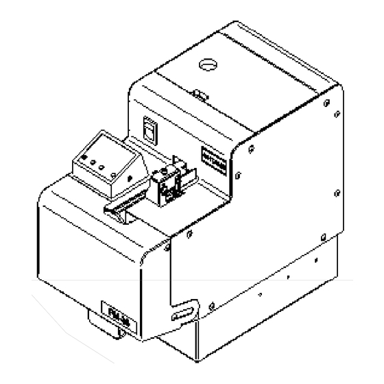
QUICHER
FM-36
NSRI Type
Operation manual (Maintenance)
・ R e a d t h e s e i n s t r u c t i o n s f o r t h e p r o p e r u s e o f t h i s m a c h i n e .
・ A f t e r h a v i n g r e a d t h e s e i n s t r u c t i o n s , k e e p t h e m i n a c o n v e n i e n t
p l a c e s o y o u o r t h e o p e r a t o r c a n r e f e r t o t h e m w h e n e v e r n e c e s s a r y .
ATTENTION : www.ohtake-root.co.jp is the only web site associated with our company.
We do not have any branches in China.
www.ohtake-root.co.jp
www.ohtake-root.co.jp
Automatic Screw Feeder
Series
HP
自動ネジ供給機
FM1MA01M a
02M
Advertisement
Table of Contents

Subscribe to Our Youtube Channel
Related Manuals for OHTAKE FM-36 Series

Summary of Contents for OHTAKE FM-36 Series
- Page 1 . ATTENTION : www.ohtake-root.co.jp is the only web site associated with our company.
- Page 2 CAUTION ! Note:About the screws stock limit If too much screws are placed into the storage chamber of the feeder, it may affect the process of screw feeding, or cause the machine to be overloaded and malfunction. Please refer to the diagram below and carefully adjust the screw level to be 2 ~ 3mm below upper edge of the rail. (When the scoop plates are at the lowest point.) ○...
-
Page 3: Table Of Contents
4. Identifying the Unit Type------------------------5 11.External dimension---------------------------------------------------25 5. Getting this machine ready-------------6 1. Before Use Thank you very much for purchasing our Automatic Screw Feeder, 『FM-36 series』 . Please check up the accessories supplied with it before using it. Accessories Operation manual x1... - Page 4 AC adapter Use the accessories AC adapter only. CAUTION Attachment of the earth wire When the earth wire is connected, loosen the screw near the mark once. After attaching the earth wire,tighten the screw again. Rail Do not scratch the rail. Do not apply any oil or grease to the rail. the bottom of the main body Compatible screws Use the specified screws only.
-
Page 5: Precautions In Ejecting Screws
Precautions in Ejecting Screws Please use maximum care in ejecting screws from the Screw bin for changing screw types, replacing the rail and so forth. ◎ Screws could fall into the inside of this machine if ejection is mishandled. ◎ If this machine is tilted or turned back with screws being accumulated at the unloading port or left on the rail, screws may fall into the inside of this machine. -
Page 6: Component Names
3. Component Names Rail front-rear Screw bin position lock screw Screw bin lid Power switch Passage window (in the passage LCD panel plate) Bit guide assembly Passage plate Passage plate lock screw Shutter (installed in front Bin scooping Rail of the passage plate) plate assembly Screw bin... -
Page 7: Identifying The Unit Type
4. Identifying the Unit Type Before using this machine, check to make sure that the nominal diameter of the applied screw meets the unit type. To identify the unit type, remove the front cover and the rail assembly and look at the labels affixed to the rail assembly and the Escaper Unit. -
Page 8: Getting This Machine Ready
5. Getting this machine ready 5.1 Supply of Screws Loading this machine with too many screws could CAUTION adversely affect their alignment and transfer. The approximate maximum supply of screws is illustrated in the figure at right. Consult this figure for loading screws. •... - Page 9 5.2 Unloading Screws This machine ships factory-adjusted with handle pan-head screws. This machine should require the following checks and adjustments depending on the kind of screw to use: LCD panel setting change Brush check and adjustment Passage plate check and adjustment ...
- Page 10 5.3 LCD Panel Indicators and Settings ◎ LCD Panel Indicators <Preset count indicator> Preset count indicator Preset total indicator • Shows a preset count of screws. • Decrements each time a screw is delivered to the unloading port. • Is reset to the preset count when the preset count of screws has accumulated at the unloading port.
- Page 11 ◎ LCD Panel Settings LCD panel settings can be changed while this machine is shut down after it has been powered on. <<CLEAR>> <Clearing the preset total indicator → CLEAR> Resets the preset total • Press the CLEAR button for about 2 seconds, and the buzzer sounds to “0000.”...
- Page 12 5.4 Brush Check and Adjustment Turn the power switch on, then off to keep the brush roughly level. Brush height Turn off the power switch before performing check adjustment screws CAUTION and adjustment work. Put a screw to use in the screw bin and turn the power switch on, then off Brush to place the screw into the rail groove.
- Page 13 作業内容 (部品名 5.6 Holding Plate Check and Adjustment ネジ押え板固定ネジ Holding plate setscrews ネジ押え板固定ネジ ビットガイドAssy上下調整ネジ Check the Holding plate position. Bit guide assembly vertical adjustment screw ビットガイドAssy上下調整ネジ • Without a clearance between the head of the applied screw in the rail groove and the Holding plate, screws could be stuck. Too large a clearance could cause screws to overlap or cause them to pop out and fall into the machine.
- Page 14 5.7 Timer Check and Adjustment The applied screw transfer speed varies depending on the screw type. A longer timer interval setting is recommended for screws with a lower transfer speed, and a shorter timer interval setting is recommended for screws with a faster transfer speed. Short •...
- Page 15 5.8 External Output Signal Line This machine has an external output signal line, allowing for external Give one or more turns to the signal line around the coaching clip so it generation of a signal synchronized with the timing at which the LCD panel can be safely pulled from outside.
-
Page 16: Maintenance
6. Maintenance Remove two front cover mounting screws, including one on the opposite side Turn off the power switch before performing check and CAUTION adjustment work. Loosen the Rail front-rear position Eject all applied screws from within this machine before lock screw and pull out the rail. -
Page 17: Replacing Parts
7. Replacing Parts 7.1 Replacing the Brush Brush assembly mounting screw Turn off the power switch before performing check and CAUTION adjustment work. If the tip of the brush has worn to such degree that the brush can no longer brush away screws in an abnormal posture, replace it with a new Must not hit brush. - Page 18 7.3 Replacing the Escaper Unit Turn off the power switch before performing check and Remove two mounting screws, including one on adjustment work. CAUTION the opposite side When using screws of different nominal diameters, replace the passage paltes for both the rail assembly Remove the sensor and the Escaper Unit.
-
Page 19: Points To Check Before Requesting Repair Services
8. Points to Check Before Requesting Repair Services CAUTION Turn the power switch off before troubleshooting this machine. Symptom Cause Action This machine won’t start when • Power is not connected. • Check that AC adapter power connection. the power switch is turned on •... - Page 20 Symptom Cause Action Screws won’t come flowing • The brush cannot brush away screws in an • Adjust the brush. abnormal posture. Adjust the passage plate. Putting an appropriate supply of screws in the Screw bin could fix the problem. •...
- Page 21 Symptom Cause Action Screws have fallen into the rail • Screws having a smaller nominal diameter • Load screws of the specified nominal diameter. groove than specified have been loaded. • Screws having a shorter overall length than • Uncorrectable. specified have been loaded.
- Page 22 Symptom Cause Action Screws cannot be unloaded at • Screws have been arrested halfway in the • Adjust the Holding plate position. the unloading port rail. • Screws do not smoothly transfer from the rail • Adjust the groove position of the rail and the to the escaper disc.
- Page 23 Symptom Cause Action Scooping won’t stop when a • Improperly adjusted Timer setting control • Adjust the Timer setting control screw. metered count of screws has screw been unloaded at the unloading port • Remove the cover and then the screw fallen Screws have fallen into the inside inside.
-
Page 24: Principal Specifications
9. Main Specifications Exclusive adapter Input :AC100~240V 50/60Hz Note: (Switching type) Output :DC15V • Each model comes with a standard model-specific rail. 130W X 254D X 201H (mm) Dimension • Each model comes with a standard model-specific escaper disc. • Each model comes with a standard model-specific passage plate. Approx.6.0kgf Weight •... - Page 25 Screw Exchange Escaper Unit Passage Rail model Type Model number nominal model plate model number diameter number number number -In the Exchange Kit ordered FM-3630 3.0 FR30SET FR30 W3630 separately, Rail Assembly, Escaper disc Assembly, Passage plate are FM-3635 3.5 FR35SET FR35 W3635...
-
Page 26: Warranty Terms
10. Warranty For users within Japan,the product is warranted for a period of six months after the date of delivery. Such warranty will not be ap- plicable to purchases or users outside of Japan.If any troubles should occur, however, contact your local dealer. The solutions to the following situations may be implemented at a reasonable charge without regard to the warranty period. -
Page 27: External Dimension
11.External dimension Timer setting control DC jack Product seal [unit : mm] – 25 –... - Page 28 Fax +81-191-24-3145 Fax +81-191-24-3145 「Quicher」 「OHTAKE」 「OHTAKE ・ ROOT KOGYO」 is a trademark or registerd trademark of OHTAKE ・ ROOT KOGYO CO.,LTD.] 「Quicher( クイッチャー)」 「OHTAKE」 「OHTAKE ・ ROOT KOGYO」 は、 株式会社 大武 ・ ルート工業の商標又は登録商標です。 The specification and the design of a product may be changed without a preliminary announcement for improvement.
Need help?
Do you have a question about the FM-36 Series and is the answer not in the manual?
Questions and answers