
Summary of Contents for Brüel & Kjær Vibro VIBROTEST 60
- Page 1 VIBROTEST 60 Technische Dokumentation Technical Documentation Dokumentation Technique C006389.01...
- Page 2 All rights reserved. No part of this publication may be reproduced, stored in a retrieval system or transmitted, in any form, or by any means, electronic, mechanical, photocopying, recording or otherwise without prior written permission from Brüel & Kjær Vibro GmbH. The right to make changes at any time without notice is reserved.
-
Page 3: Table Of Contents
VIBROTEST 60 Contents Contents Precautionary information ............10 Introduction ................12 Tasks the VIBROTEST 60 can perform ............12 2.1.1 The concept ..........................12 2.1.2 Advantages of the VIBROTEST 60 ..................12 Module overview ................... 14 Extent of delivery ..................15 Mechanical construction ................ - Page 4 VIBROTEST 60 Technische Dokumentation Technical Documentation Dokumentation Technique C006389.01...
- Page 5 Tous droits réservés. La duplication ou la copie de cette documentation, totale ou partielle, par quel que moyen que ce soit, est interdite sans l’autorisation écrite préalable de Brüel & Kjær Vibro GmbH. Nous nous réservons la possibilité de réaliser des améliorations sans préavis.
- Page 6 Contents VIBROTEST 60 SETUP - Adjustments ..............29 System setup ....................29 4.1.1 Channels ..........................29 4.1.2 Setup 1=2 ..........................29 4.1.3 Date ............................30 4.1.4 Time ............................30 4.1.5 Units ............................30 4.1.6 Speed ............................30 4.1.7 Speed / Ref..........................31 4.1.8...
- Page 7 VIBROTEST 60 Contents Envelope Analysis / BCS ................45 4.5.1 Envelope analysis - BCS mode (Bearing Condition Signature) ..........45 4.5.2 Envelope analysis - SED mode (Selective Envelope Detection) ..........46 4.5.3 Frequency analysis parameters ....................48 4.5.4 No. of Lines ..........................48 4.5.5...
- Page 8 Contents VIBROTEST 60 Balancing ...................... 56 4.9.1 Sensors ........................... 56 4.9.2 Unit ............................57 4.9.3 No. of planes ........................... 57 4.9.4 Correction type ........................57 4.9.5 Adaptive Mode ........................58 4.9.6 Mass Units..........................58 4.10 Service functions ..................59 4.10.1 Buttons test ..........................
- Page 9 VIBROTEST 60 Contents »Envelope Analysis / BCS« ................80 »CPB Spectra« ..................... 82 5.4.1 Executing a measurement ...................... 82 »Process-value« measurement ..............84 5.5.1 Listing function ........................85 »Tracking Analysis« measurement ............... 86 5.6.1 Free-running measurement..................... 87 5.6.2 Measurement vs. Speed ......................88 5.6.3...
- Page 10 Contents VIBROTEST 60 Storage of the balancing procedure ............110 Selecting Balancing / Executing the Setup ..........111 Single-plane balancing steps with polar correction example ..... 113 Single-plane, repeat balancing steps with polar correct-ion example ..120 Two-plane Balancing steps with component correction example ....122...
- Page 11 Exchanging battery sets ......................146 11.1.3 Charging ..........................146 11.1.4 LED Charge monitoring ......................147 11.1.5 Battery maintenance with a VIBROTEST 60 in storage ............148 11.1.6 Disposal ..........................148 11.1.7 Battery replacement ......................148 Technical Data ................. 149 12.1 Safety conformance ..................
- Page 12 Contents VIBROTEST 60 12.5 Optical reference pickup P - 95 ..............161 12.5.1 Application ..........................161 12.5.2 Operating Principle ........................ 161 12.5.3 Technical Data ........................162 12.5.4 Reference mark........................163 12.5.5 Mounting / Adjustment ......................164 12.5.6 Problems with the reference signal ? ..................164 Appending EG-conformance statements ........
- Page 13 VIBROTEST 60 Contents _________________________________________________________________________________ © VTEST60E July 2013 V4.46ff C102 853.002 Page 9 of 168...
-
Page 14: Precautionary Information
Please check the power in your region and compare it with the power range capability of the battery charger unit of the instrument before commissioning. The battery set of the VIBROTEST 60 must not remain in the instrument during transportation! The connections of the battery set must not be short-circuited! Page 10 of 168 C102 853.002... - Page 15 VIBROTEST 60 Precautionary information Note: • VIBROTEST 60 should only be operated with its covers on. • Do not touch the charging contacts under the instrument. This could result in faulty operation of the functions due to electro-static discharge. •...
-
Page 16: Introduction
Vibration analyser • Field Balancing instrument • Data-collector. VIBROTEST 60 is the realisation of a measuring instrument technically designed for evaluation of machine condition, accurate diagnosis of damage and faults and achievement of the most modern standard for „condition-based„ maintenance strategy. - Page 17 VIBROTEST 60 Introduction • Real 2-channel measurement plus speed • Small, light-weight (900 g), single-hand operated instrument • Latest quality in Data-collector technology with − extreme speed of measurement and simultaneous processing of up to 5 different measurement types −...
-
Page 18: Module Overview
Introduction VIBROTEST 60 Module overview The following documentation describes all available modules of the VIBROTEST 60. In any individual case those modules which correspond to the order acknow-ledgement are released. Module Functions Module 1.1 • Absolute bearing vibration : Basic Module Overall values for machine •... -
Page 19: Extent Of Delivery
VIBROTEST 60 Introduction Extent of delivery The extent of delivery of the basic VIBROTEST 60 instrument consists of the following components: 1 x VIBROTEST 60 measuring instrument incl. Basic Module 1.1: „Overalls for machine evaluation“ 1 x Power / charger unit... -
Page 20: Mechanical Construction
Display unit LED: GREEN Instrument On Residual battery life < 2 Min. (LED is „RED“ only when VIBROTEST 60 has been on for more than 10 min.) Softkeys Cursor control buttons The back-light is switched On by pushing any button. The function of the respective button is... -
Page 21: Vibrotest 60 Measuring Instrument
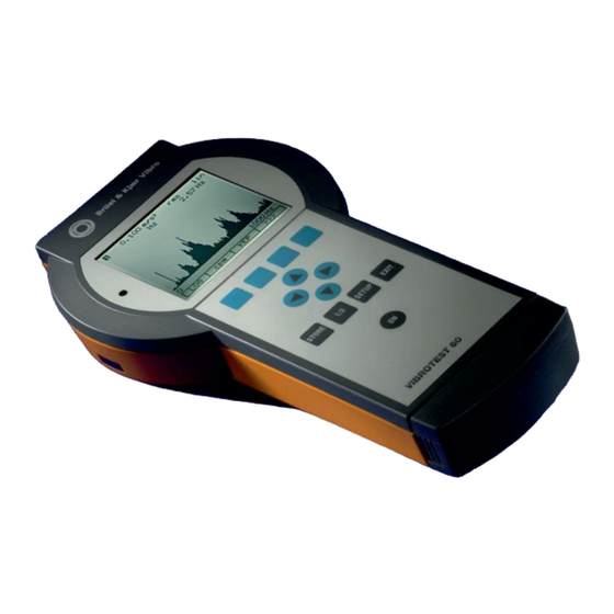
VIBROTEST 60 Introduction 2.4.1 VIBROTEST 60 measuring instrument The single-hand housing has the following components • Display unit • Push-button area • Sensor connections • Battery set • PC-card drive Display unit Backlit graphic LCD display • Resolution of 160 x 140 pixels •... -
Page 22: Power / Battery Charger Unit
After this switch has cooled down sufficiently the electrical connection is again automatically made and the VIBROTEST 60 can be switched on once more. PC-card drive The VIBROTEST 60 is equipped with a drive for PC-cards. This is located below the battery set and can be accessed after removing the lower housing cover. -
Page 23: Operation
VIBROTEST 60 Introduction Operation 2.5.1 Softkeys Various menus corresponding to the selected measurement, analysis or configuration tasks are displayed. The bottom row in each menu is reserved for the display of softkey text. By pushing the softkey below the text the respective function is selected. -
Page 24: Cursor Buttons
Introduction VIBROTEST 60 2.5.2 Cursor buttons Depending on the menu being displayed, various functions can be performed in connection with the cursor position. Cursor display with FFT-, Envelope Analysis and CPB-spectra The cursor can be moved along the X-axis using the cursor control buttons. -
Page 25: The Window Display
Exit from the current function menu and return to the previous menu. All changes to the configuration in the current menu or displayed measurements in the current menu are deleted. ON / OFF toggle switch for the VIBROTEST 60 2.5.4 The window display Channel number Menu title... -
Page 26: Zoom Function Without The Cursor
Introduction VIBROTEST 60 2.5.5 Zoom function without the cursor During the acquisition of a spectrum and after a spectrum measurement is completed the X- and Y-axes can be zoomed. Note: If „Setup 1=2: Yes„ has been defined in the System Setup, all actions in the X-axis (zoom and cursor movement) will be effected simultaneously at both channels. - Page 27 VIBROTEST 60 Introduction Zooming the Y-axis The softkey shows which zoom function will be currently active ! Using the cursor buttons the Y-axis can be zoomed. These buttons alter the full scale value of the Y-axis. The full scale value of the Y-axis is numerically displayed.
-
Page 28: Zoom Functions With Activated Cursor
Introduction VIBROTEST 60 2.5.6 Zoom functions with activated cursor During spectrum acquisition and after a spectrum has been measured. • Information about individual spectral lines can be displayed with the cursor and • The X- and Y-axes can be zoomed. - Page 29 VIBROTEST 60 Introduction Corresponding to the frequency line at which the cursor is positioned, the amplitude and frequency are displayed in numeric form above the diagram. In addition to the numeric values the associated units and the selected signal-detection type are also displayed.
- Page 30 Introduction VIBROTEST 60 Zooming the Y-axis The softkey shows which zoom function will be currently active ! Using the cursor buttons the Y-axis can be zoomed. This alters the scaling of the Y-axis. Y-axis without zoom Y-axis with zoom The full scale value of the Y-axis is automatically determined, corresponding to the largest amplitude, in the ranges 1, 2, 5 or the power of ten thereof.
-
Page 31: Operational Modes
100 measurements can be stored in a buffer memory during measurement using the Listing function. These values stored in the buffer memory can be permanently stored to the PC-card and analysed later using either the VIBROTEST 60, or the PC programs XMS or VIBRO-REPORT. _________________________________________________________________________________ ©... -
Page 32: Data-Collector Mode
Unbalance correction can be done in polar, component or unit mass format. VIBROTEST 60 offers the option, at rotors that have previously been balanced and the balancing procedure stored on the PC- card, to execute „Repeat balancing„ without conducting any new test runs. -
Page 33: Setup - Adjustments
VIBROTEST 60 SETUP - Adjustments SETUP - Adjustments System setup The System setup is selected using either the softkey »Setup« in the main menu or via the function button SETUP. The displayed parameter setup resp. adjustments are accepted and the previous menu appears. -
Page 34: Date
SETUP - Adjustments VIBROTEST 60 4.1.3 Date Format: dd / mmm / yy mmm / dd / yy yy / dd / mmm yy / mmm / dd dd = Day, mmm = Month, yy = Year Note: See chapter 9.9 4.1.4... -
Page 35: Speed / Ref
VIBROTEST 60 SETUP - Adjustments 4.1.7 Speed / Ref. The values for calculating the ratio between machine speed / reference impulses have to be entered 1 ... 999 Revolutions (Counter) 1 ... 999 Reference impulses (Denominator) Note: The minimum ratio is 1/99 and the maximum 99/1. -
Page 36: The Cursor Control
Entry of decimal points, numbers and units Decimal points numbers selected VIBROTEST 60 using the cursor buttons . The process is explained in the following example. In the example below the objective is to set up the sensor‘s sensitivity for 20 mV/mm in the Process-values Setup. - Page 37 VIBROTEST 60 SETUP - Adjustments Entering the numeric values Using the cursor buttons , position the cursor on the numeric value which is to be changed. Select the numeric value using the cursor buttons Selecting the unit Position the cursor on the unit that is to be...
-
Page 38: Vibration Measurement
SETUP - Adjustments VIBROTEST 60 Vibration measurement The displayed parameter setup resp. adjustments are accepted and the previous menu appears. EDIT Switch to the functional selection/ entry menu for editing the para-meter values. 4.3.1 Overall Vibration 4.3.1.1 Sensors AS-06x/07x Vibration acceleration sensor... - Page 39 VIBROTEST 60 SETUP - Adjustments 4.3.1.2 Unit / Signal detection Unit Signal detection m/s² peak mm/s peak peak peak calculated µm peak peak calculated mils Note: The possible selection of the unit is dependent on the sensor type and the predefined unit system in the menu »System Setup«...
- Page 40 SETUP - Adjustments VIBROTEST 60 Low-pass 10 Hz 125 Hz 1600 Hz 12.5 Hz 160 Hz 2000 Hz 16 Hz 200 Hz 2.5 kHz 20 Hz 250 Hz 3.15 kHz 25 Hz 315 Hz 4 kHz 31.5 Hz 400 Hz...
-
Page 41: Bcu / Bandpass
Vibration acceleration sensor AS-1x/2x/3x Vibration acceleration sensor (only with additional adapter AC-630) Variable Only acceleration sensors not requiring power from the VIBROTEST 60 0.01 ... 1000.00 mV / unit V / unit Variable CCS* Only acceleration sensors requiring power from the VIBROTEST 60 + 24 V, 2 ...4 mA... - Page 42 SETUP - Adjustments VIBROTEST 60 4.3.2.2 Unit / Signal detection Unit Signal detection none Bandpass Unit Signal detection AS - Sensors: m/s² Variable sensors: Sensor-definition unit 4.3.2.3 Filter If Bandpass is selected the desired high-pass and low-pass must be set up.
- Page 43 VIBROTEST 60 SETUP - Adjustments Low-pass : 800 Hz 8 kHz 1000 Hz 10 kHz 1250 Hz 12.5 kHz 1600 Hz 16 kHz 2000 Hz 20 kHz 3,15 kHz 2.5 kHz 4 kHz 5 kHz 6,3 kHz Advice: The corner frequency series of the high-pass and low-pass are planned in the same steps;...
-
Page 44: Record Mode
SETUP - Adjustments VIBROTEST 60 4.3.3 RECORD Mode RECORD Mode means that vibration / BCU measurements can be recorded vs. speed or time. Advice: A maximum of 6,400 measured values can be recorded. The system limits this number of measured values automatically. - Page 45 VIBROTEST 60 SETUP - Adjustments 4.3.3.2 RECORD Mode f(t) If the RECORD Mode f(t) is selected the following parameters must be set up: 4.3.3.2.1 Measurement time T maximum 99,999 seconds minimum 10 seconds 4.3.3.2.2 Interval ∆ t ∆ t maximum 80 seconds minimum 0.1 seconds...
-
Page 46: Spectrum / Cepstrum
SETUP - Adjustments VIBROTEST 60 Spectrum / Cepstrum The displayed parameter setup resp. adjustments are accepted and the previous menu appears. EDIT Switch to the functional selection/ entry menu for editing the parameter values. 4.4.1 Sensors AS-06x/07x Vibration acceleration sensor... -
Page 47: Unit / Signal Detection
VIBROTEST 60 SETUP - Adjustments 4.4.2 Unit / Signal detection Unit Signal detection m/s² peak mm/s peak peak µm 4.4.3 Filter High-pass 1 Hz 2 Hz 5 Hz 10 Hz Low-pass 20 Hz 1 kHz 50 Hz 2 kHz 100 Hz... -
Page 48: Averaging Mode
SETUP - Adjustments VIBROTEST 60 4.4.6 Averaging mode Frequency domain Time domain Advice for the setup „Time domain“: This is active only when the speed measurement is switched on in the System setup and the speed signal is acquired. 4.4.7 No. -
Page 49: Envelope Analysis / Bcs
Vibration acceleration sensor AS-1x/2x/3x Vibration acceleration sensor (only with additional adapter AC-630) Variable Only acceleration sensors not requiring power from the VIBROTEST 60 0.01 ... 1000.00 mV / unit V / unit Variable CCS* Only acceleration sensors requiring power from the VIBROTEST 60 + 24 V, 2 ...4 mA... -
Page 50: Envelope Analysis - Sed Mode (Selective Envelope Detection)
SETUP - Adjustments VIBROTEST 60 4.5.2 Envelope analysis - SED mode (Selective Envelope Detection) The displayed parameter setup resp. adjustments are accepted and the previous menu appears. EDIT Switch to the functional selection/ entry menu for editing the parameter values. - Page 51 VIBROTEST 60 SETUP - Adjustments 4.5.2.3 Filter High-pass : 630 Hz 6.3 kHz 800 Hz 8 kHz 1000 Hz 10 kHz 1250 Hz 12.5 kHz 1600 Hz 16 kHz 2000 Hz 2.5 kHz 3.15 kHz 4 kHz 5 kHz Low-pass :...
-
Page 52: Frequency Analysis Parameters
SETUP - Adjustments VIBROTEST 60 4.5.3 Frequency analysis parameters 4.5.3.1 Filter High-pass 1 Hz 2 Hz 5 Hz 10 Hz Low-pass 20 Hz 200 Hz 2 kHz 20 kHz 50 Hz 500 Hz 5 kHz 100 Hz 1 kHz 10 kHz The span between high and low-pass must be smaller than the span selected for the SED filter setups. -
Page 53: Averaging Mode
VIBROTEST 60 SETUP - Adjustments 4.5.6 Averaging mode Frequency domain Time domain Advice for the setup „Time domain“: This is active only when the speed measurement is switched on in the System setup and the speed measurement is acquired. 4.5.7 No. -
Page 54: Cpb-Spectrum
SETUP - Adjustments VIBROTEST 60 CPB-spectrum Constant Percentage Bandwidth The present parameter entries or setups are accepted. The program returns to the previous menu. EDIT Switch to the selection/entry menu associated with the function for editing the parameter values. 4.6.1... -
Page 55: Unit / Signal Detection
VIBROTEST 60 SETUP - Adjustments 4.6.2 Unit / Signal detection Unit Signal detection m/s² peak mm/s peak peak µm mils Note: The possible selection of the unit is dependent on the sensor type and the predefined unit system in the menu »System Setup«... -
Page 56: Process Values
SETUP - Adjustments VIBROTEST 60 Process Values The displayed parameter setup resp. adjustments are accepted and the previous menu appears. EDIT Switch to the functional selection/ entry menu for editing the parameter values. 4.7.1 Sensor sensitivity Physical Signal Units m³/s °C... -
Page 57: Tracking Analysis
VIBROTEST 60 SETUP - Adjustments Tracking Analysis The displayed parameter setup resp. adjustments are accepted and the previous menu appears. EDIT Switch to the functional selection/ entry menu for editing the parameter values. Note: The setup affects both channels, regardless of the setting „Setup 1 = 2„... -
Page 58: Unit
SETUP - Adjustments VIBROTEST 60 4.8.2 Unit Unit Signal detection m/s² peak mm/s peak peak µm mils 4.8.3 Additional Order 2. - 99. Order* 0 = additional order is not active Note: The 1st order is always measured 4.8.4 RECORD 4.8.4.1... - Page 59 VIBROTEST 60 SETUP - Adjustments 4.8.4.1.3 Direction Coastdown* Run-up* ∗ The setting is relevant for both channels. At the end of the setup, confirm by pushing »OK«. 4.8.4.2 RECORD Mode f(t) When the RECORD Mode f(t) is selected the following parameters must be set up: 4.8.4.2.1 Measurement time T...
-
Page 60: Balancing
SETUP - Adjustments VIBROTEST 60 Balancing The displayed parameter setup resp. adjustments are accepted and the previous menu appears. EDIT Switch to the functional selection/ entry menu for editing the para-meter values. Note: After the initial run only the parameters „Correction type“ and “Adaptive Mode”... -
Page 61: Unit
VIBROTEST 60 SETUP - Adjustments Note: When moving-coil vibration velocity sensors of the type VS-079 and VS-080 are connected a linearisation between 1 Hz…20Hz is active. With moving-coil vibration velocity sensors which are „variable„ this linearisation is not active. ∗... -
Page 62: Adaptive Mode
SETUP - Adjustments VIBROTEST 60 4.9.5 Adaptive Mode aktive inaktive Advice: The parameter for the Adaptive Mode is preset to active. When Repeat Balancing is performed the Adaptive Mode is automatically set inactive by the System. 4.9.6 Mass Units The mass units are not defined in the Setup but are determined when the first test weights are attached during the balancing procedure. -
Page 63: Service Functions
The »Service« menu is opened using the following steps: • Softkey »INFO« in the menu VIBROTEST 60. • Softkey »SERVICE« in the menu VIBROTEST 60 / INFO. The individual functions are activated by selecting them using the cursor buttons and then the softkey »SELECT«. -
Page 64: Vibrotest
It is mandatory to note and to follow the instruction, that only 32 MB PC cards AC-603/32 shall be used. These PC cards shall be ONLY formated in the VIBROTEST 60 and NOT in the PC- card drive! To guarentee the functionality the PC card formating has to be performed in the VIBROTEST 60 according to the instructions described in section 4.10. -
Page 65: Calibration Info
VIBROTEST 60 / INFO. 4.10.5 Error reports Errors which require the VIBROTEST 60 to be switched off are stored with a number and the time the error occurred in an error report as instructed by the error code. -
Page 66: Acquiring And Displaying Measurements
Acquiring and displaying measurements General In this chapter all the functions are described which can be carried out using a VIBROTEST 60 which is equipped with all modules. Functions which have not been released are identified by the „* *„ and are not active. - Page 67 Opens the menu „System Setup„ REPORT Opens the Reports selection list. Measurement task configuration The VIBROTEST 60 must be configured for the current measurement task. The configuration menu is selected using the »SETUP« button after the operating mode has been selected.
-
Page 68: Overall Vibration / Bcu Measurement
Acquiring and displaying measurements VIBROTEST 60 »Overall Vibration / BCU measurement« Measured value 1: Unit Vibration Signal detection Measured value 2: Unit Bearing Condition Unit Measured value 3: Speed START The measurement is started. „STOP„ is displayed and the channel number flashes to indicate that the measurement is in progress. -
Page 69: Listing Function
VIBROTEST 60 Acquiring and displaying measurements Averaging the measured values The acquired measurements can be averaged. The averaging function is switched on using the »AVERAGE« softkey. The active averaging function is indicated by the inverse display of the text „AVERAGE„. The averaging function remains active until the function is switched off by pushing the softkey »AVERAGE«... - Page 70 Acquiring and displaying measurements VIBROTEST 60 Procedure: Storing in the Listing memory during a measurement The following example is used to illustrate the procedure. • Start the measurement with the softkey »START«. The measurement is numbered „1„ in the display.
- Page 71 . The loaded measure-ment is given the number „1„ in a Listing memory. The counter number on the display shows the number „2„. The VIBROTEST 60 is now ready to take the new measurement number „2„. • Start the new measurement with softkey »START«.
-
Page 72: Recording Measurements In A Specific Speed Range Or Time Interval
Acquiring and displaying measurements VIBROTEST 60 5.1.2 Recording measurements in a specific speed range or time interval 5.1.2.1 Measurement vs. speed f(n) Measurement window Start - Stop speed Meas. value 1: Unit: Signal detection Meas. value t 2: Unit: Signal detection Meas. - Page 73 Activate the measurement recording with »REC«. Can also be activated after Start of measurement. • Start the measurement process with »START«. • The VIBROTEST 60 stores the measurements. The process ends automatically when f is reached or can be manually with »STOP«. •...
- Page 74 Acquiring and displaying measurements VIBROTEST 60 Amplitude diagram without cursor Measurement range, Unit, Signal detection, Scaling Amplitude diagram Vibration measured value BCU – Measured value Speed range Amplitude diagram with cursor Measurement range, Unit, Signal detection, Scaling Amplitude diagram Speed at Cursor position Speed range X-axis zoom is active.
- Page 75 VIBROTEST 60 Acquiring and displaying measurements Graphic resolution • A maximum of 6400 single measured values per channel can be recorded. • the maximum resolution amounts to 1 rpm resp. ) / 6400 • The number of single measured values is: <~ 2...
- Page 76 Acquiring and displaying measurements VIBROTEST 60 5.1.2.2 Measurement vs. Time f(t) Measurement window Total meas. time, time interval Meas. Value 1: Unit Signal detection START The measurement process is started. „STOP„ is dis- played and the channel number flashes to indicate that the measurement is in progress.
- Page 77 With the function button »EXIT« you can switch back to a numeric display. • The VIBROTEST 60 stores the measurements. The meas- urement ends manually with »STOP« or automatically after the set time has elapsed. •...
-
Page 78: Spectrum / Cepstrum
Number of averages completed (e.g. 1) »0-1000 Hz«: Frequency range Depending on the settings in SETUP for the type and number of averages the VIBROTEST 60 proceeds in various different ways. Defining the averaging function is done in the window »Setup Spectrum«. START The measurement process is started. - Page 79 VIBROTEST 60 Acquiring and displaying measurements AVERAGE On / Off switch for averaging. The type of averaging is defined in the SETUP. Y-axis Zoom is active. Using the cursor buttons the cursor can be moved. X-axis Zoom is active. Using the cursor buttons the cursor can be moved.
- Page 80 Acquiring and displaying measurements VIBROTEST 60 Display range, Unit, Signal detection, Scaling Speed Linear scaling Info line* *Info line: »0-1000 Hz«: Frequency range The X-axis can be displayed in either Hz or cpm units. The selected unit is displayed directly on the screen.
-
Page 81: Averaging Functions
VIBROTEST 60 Acquiring and displaying measurements 5.2.2 Averaging functions The averaging functions available in the VIBROTEST 60 are explained in the following: Averaging in the frequency domain Averaging in the frequency domain is a pure arithmetic amplitude averaging of the spectral lines over time. - Page 82 The start and stop for the signal observation time is manually given by the pushing the softkeys »START« and »STOP«. Activating the Peak Hold method in the VIBROTEST 60: This is active in the VIBROTEST 60 when: •...
-
Page 83: Display Of Low Frequencies
VIBROTEST 60 Acquiring and displaying measurements 5.2.3 Display of low frequencies Fading out of frequency lines At maximum zoom in the X-axis (Line spacing of display = Line spacing of the measurement): • The frequency line at 0 Hz is not displayed; the amplitude is „0„. -
Page 84: Envelope Analysis / Bcs
* Info line: »0-1000 Hz«: Frequency range Depending on the selections made in the SETUP for the type and no. of averages the VIBROTEST 60 behaves in different ways. Determination of the averaging function is done in the window »Setup«. START The measurement process is started. - Page 85 VIBROTEST 60 Acquiring and displaying measurements Display range, Signal detection, Scaling, Speed Info line* * Info line: »0-1000 Hz«: Frequency range The scaling for the Y-axis can be switched between logarithmic „LOG“ and linear „LIN“ format. The se- lected format is displayed at the upper right of the screen.
-
Page 86: Cpb Spectra
Acquiring and displaying measurements VIBROTEST 60 »CPB Spectra« 5.4.1 Executing a measurement Display, Detection, Y axis: 10 dB Scaling, Speed Graduation lines X-axis description START The measurement process is started. „STOP“ is dis- played and the channel number flashes to indicate that the measurement is in progress. - Page 87 Depending on the frequency resolution it may happen that the spectrum is in fact wider than width of the display of the VIBROTEST 60. Using the cursor-buttons the spectrum display can be shifted to the left or right on the instrument’s display.
-
Page 88: Process-Value« Measurement
Acquiring and displaying measurements VIBROTEST 60 »Process-value« measurement Measured value: Unit Process-value Unit Measured value: Speed START The measurement is started. „STOP„ is displayed to indicate that the measurement is in progress. STOP The measurement is ended. „START„ is displayed to indicate that the measurement has stopped. -
Page 89: Listing Function
VIBROTEST 60 Acquiring and displaying measurements Averaging the measured values The acquired measurements can be averaged. The averaging function is switched on using the »AVERAGE« softkey. The active averaging function in indicated by the inverse display of the text „AVERAGE„. The averaging function remains active until the function is switched off by pushing the softkey »AVERAGE«... -
Page 90: Tracking Analysis« Measurement
Acquiring and displaying measurements VIBROTEST 60 »Tracking Analysis« measurement In Tracking Analysis there are two operational modes: • Free-running measurement with a manual control of Start/Stop of the measurement, and the option of storing the individual measurements in the Listing memory. -
Page 91: Free-Running Measurement
VIBROTEST 60 Acquiring and displaying measurements ___________________________________________________________________ 5.6.1 Free-running measurement Measurement window Meas. value 1st order Unit Amplitude/Phase Signal detection Meas. value nth order Unit Amplitude/Phase Signal detection Speed / Unit Speed / Reference START The measurement process is started. „STOP„ is dis- played and the channel number flashes to indicate that the measurement is in progress. -
Page 92: Measurement Vs. Speed
Acquiring and displaying measurements VIBROTEST 60 5.6.2 Measurement vs. Speed Measurement window Meas. value 1st order Unit Signal detection Meas. value nth order Unit Signal detection Speed / Unit Speed / Reference ratio START The measurement is started. “STOP” is displayed and the channel number flashes to indicate that the measurement is in progress. - Page 93 Activation of the measurement recording with »REC«. This can also be activated after the measurement is started. • Start the measurement using »START«. • VIBROTEST 60 stores the measurement. Measurement is stopped manually with »STOP« or automatically when the range f is completed. •...
- Page 94 Acquiring and displaying measurements VIBROTEST 60 Amplitude/Phase diagram without cursor Display range, Unit, Signal detection Amplitude diagram Phase diagram 0°-Line Speed range Amplitude/Phase diagram with cursor Meas. value, Unit, Signal detection, Phase, Amplitude diagram speed at the cursor position Phase diagram 0°-Line...
- Page 95 VIBROTEST 60 Acquiring and displaying measurements ___________________________________________________________________ Cursor displays There are two types of cursor displays - a straight-line cursor and a dotted-line cursor. • With a straight-line cursor, the measured values (amplitude and phase) stored in the measurement memory are displayed.
-
Page 96: Measurement Vs. Time
Acquiring and displaying measurements VIBROTEST 60 5.6.3 Measurement vs. time Measurement window Meas. value 1st Order Unit Signal detection Meas. value nth Order Unit Signal detection Meas. value nth Order Speed/Ref. ratio START The measurement is started. “STOP” is displayed... - Page 97 With the function button »EXIT« you can switch back to a numeric display. • The VIBROTEST 60 saves the measurements. Tzhe measurement process is ended either manually by pushing »STOP« or automatically when the set time has elapsed.
- Page 98 Acquiring and displaying measurements VIBROTEST 60 Amplitude/Phase diagram without cursor Display range, Unit, Signal detection Amplitude diagram Phase diagram Time range Amplitude/Phase diagram with cursor Measured value, Unit, Signal detection, Phase, Amplitude diagram Time at cursor position Phase diagram Time range Zoom X-axis is active.
- Page 99 VIBROTEST 60 Acquiring and displaying measurements ___________________________________________________________________ Cursor displays There are two types of cursor display – a continuous line and a dotted line. • With a continuous line cursor the measured values (Amplitude, Phase) saved in the memory are displayed.
-
Page 100: Keyboard Input
Acquiring and displaying measurements VIBROTEST 60 »Keyboard Input« In Manual Entry measured values (numeric values) can be entered and stored in the measurement memory of the VIBROTEST 60. The measured values (in numeric form) are entered using the cursor-buttons (see also chapter 4.1). -
Page 101: Data-Collector Mode
Data-collector mode Data-collector mode The task in the Data-collector mode is the acquisition of measurements at predefined measurement intervals and Points. This operational mode is selected in the VIBROTEST 60 main window. Menu title Data Collector Operating mode: SELECT The item on the menu highlighted by the cursor will be selected. -
Page 102: Selecting The Measurement Points
Data-collector mode VIBROTEST 60 Selecting the measurement Points As a rule the measurement Points are processed one after the other in the displayed sequence. To begin, the first Point in the Route is selected. Skipping measurement Points and machines If any Points on the Route cannot be measured at the required time, it is possible to skip over one or more measurement Points. - Page 103 Point. Note: If a measurement order is defined which cannot be executed by the VIBROTEST 60 with its present hardware, the identification mark » - « is allocated to the Point (for details see chapter 4.10.6 Upgrade) _________________________________________________________________________________ ©...
-
Page 104: Measurement Acquisition
Route. As a rule this softkey text is displayed only at the last Point in the Route. The measurement is done according to the SETUP data. This SETUP data cannot be changed in the VIBROTEST 60 but can only be displayed (button »SETUP«). Start measurement acquisition The measurement is started with the softkey »START«. - Page 105 VIBROTEST 60 Data-collector mode Duration of measurement acquisition The duration of the measurement depends on the measure- ment task defined in the Route. In the Data-collector mode measurement is automatically ended as soon as all the requirements of the measurement task are fulfilled.
- Page 106 Data-collector mode VIBROTEST 60 Ending the measurement acquisition After all the measurements at the Point are completed • »Measuring finished!« is displayed and • acquisition is automatically ended. After measurement has ended a Comment can be allo-cated to the measurement Point by pushing the softkey »COM«.
-
Page 107: Allocation Of Comments
VIBROTEST 60 Data-collector mode Allocation of Comments A maximum of 100 Comments are available when they have been created using the PC-software XMS. With the softkey »COM« the list of Comments is displayed. Only one Comment can be allocated to the current measure- ment task for the Point. -
Page 108: Field Balancing
(AMA and AMB) for correction panes (A and B) are calculated. Balancing of rotors in 1 / 2 planes with prognosis With this setup in the VIBROTEST 60 two balancing problems are resolved. 1-plane balancing with measurement at both... - Page 109 This means that measurement must always be simultaneously done with two sensors. Unbalance correction types Unbalance correction with VIBROTEST 60 can be done in one of three ways. • Polar correction With polar correction the location for the correction weight is freely selectable.
- Page 110 Field Balancing VIBROTEST 60 Adaptive Mode The Adaptive Mode in the VIBROTEST 60 has the settings “Ac- tive” or “Inactive”. • Active In this setting the influence co-efficients determined by the VIBROTEST 60 during the initial run, test run and check run are adapted to the present rotor condition from run to run.
- Page 111 Automatic calculation of additional correction weights for „trim balancing„ of the rotor. Repeat Balancing VIBROTEST 60 offers the option, once the rotor is balanced, to store the balancing procedure for the rotor on the PC-card so that „Repeat Balancing„ can be done in the future.
-
Page 112: Balancing User-Interface
Field Balancing VIBROTEST 60 Balancing user-interface 7.2.1 Main Balancing menu The entire balancing procedure with results of the measuring runs and corrections is displayed in the main Balancing menu. Main menu at the start of the Balancing procedure: Channel no. / Meas. plane... -
Page 113: Softkeys
In the main menu: All correction weights attached to the rotor during the current balancing procedure can be combined into one single correction weight. VIBROTEST 60 calcu- lates the resultant weight and its correct location. In the test weight entry menu: The selected test weight is added to the existing test weight. -
Page 114: Storage Of The Balancing Procedure
Field Balancing VIBROTEST 60 Storage of the balancing procedure In the VIBROTEST 60 there are two memories on the PC-card; the Flash memory and the Report memory. Flash memory The Flash memory is an internal memory that secures the data against loss. -
Page 115: Selecting Balancing / Executing The Setup
Activity at Rotor Start Balancing program Select Balancing with »SELECT«. Starting Continue with current balancing procedure VIBROTEST 60 displays the data Ensure that from the last balancing procedure. • the mechanical Starting new balancing setup between procedure: reference pickup To execute a new balancing... - Page 116 „Select the correction type“ “Adaptive Mode”. The correction type can be changed during the balancing procedure. The VIBROTEST 60 then re-cal- culates the correction weights and locations after your change. Open the menu for selecting In the case of two-plane balancing...
-
Page 117: Single-Plane Balancing Steps With Polar Correction Example
»START«. operational speed. Start measurement with »START«. Execute initial unba- lance measurement The VIBROTEST 60 measures the initial unbalance. If the measurement is varying strongly activate the averaging function with »AVERAGE«. Measurement is stopped with »STOP«. This can be done no earlier than 3 secs. - Page 118 Store the Initial unba- lance measurement The measurement is stored with »OK«. With storage the trigger level is determined in the VIBROTEST 60. Even the smallest variations in the relation between reference mark and reference pickup will cause angle errors.
- Page 119 VIBROTEST 60 dialogue VIBROTEST 60 steps Activity at Rotor Enter test weight details The VIBROTEST 60 stores the test weight details. After confirmation of the test weight the following is deter-mined: • Test weight units • Polarity of the test weight (+ = add weight, •...
- Page 120 Stop the rotor. Store the Test meas- urement Before calculating the correction weight the VIBROTEST 60 must be informed if the test weight will be removed. With »YES«: • »YES« - the test weight will be Remove the test weight removed.
- Page 121 Only in a case where the calculated correction weight is not available should some other weight be used. The VIBROTEST 60 must then be informed of the change in weight with »EDIT«. Bring the rotor to Start Check run operational speed.
- Page 122 Field Balancing VIBROTEST 60 VIBROTEST 60 dialogue VIBROTEST 60 steps Activity at Rotor Execute Check meas- urement The VIBROTEST 60 executes the measurement. Stop the measurement with »STOP«. Stop the measurement with »STOP«. Store Check meas- urement The measurement is stored with »OK«...
- Page 123 • Attach the new replaced by a single correction correction weight to weight. The VIBROTEST 60 the rotor. calculates the new single correction weight (AMA). Changing a Check run into an Initial run in a new balancing procedure can no longer be done with »CR=IR«...
-
Page 124: Single-Plane, Repeat Balancing Steps With Polar Correct-Ion Example
1. Select the Check run with »SELECT«. Start the Check run Bring the rotor to operational speed. The VIBROTEST 60 starts the measurement with »START«. Start the measurement with »START«. Execute Check measurement The VIBROTEST 60 executes the measurement. - Page 125 The Check run can be repeated with Carry out the correction »SELECT«. In the case of a repeat at the rotor. the VIBROTEST 60 assumes that the correction has been carried out at the rotor. »CR=IR« The Check run can be accepted as...
-
Page 126: Two-Plane Balancing Steps With Component Correction Example
Attach the refe- rence pickup. measurement • Attach the vibration sensors in The measurement is executed by measuring planes 1 VIBROTEST 60 in the two planes and 2. with »START«. • Bring the rotor to operational speed. Start the measurement with »START«. - Page 127 The measurements for both planes is stored with »OK«. With storage the trigger level is determined in the VIBROTEST 60. Even the smallest variations in the relation between reference mark and reference pickup will cause angle errors. Store the measurements The measurement can be repeated with »OK«.
- Page 128 Confirm the entry with »OK«. Bring the rotor to Testlauf A starten operational speed. The measurement is executed by VIBROTEST 60 at both planes with »START«. The test weight (TMA) is dis-played in the measurement menu Start the measurement with »START«.
- Page 129 Activity at Rotor Store Test run A Stop the rotor. To calculate the correction weight the VIBROTEST 60 must be informed whether the test weight A will be removed from the rotor. • »YES« - the test weight A will be With »YES«: Remove...
- Page 130 If balancing in only one plane is sufficient. Store Test run B Stop the rotor. Before calculating the correction weights the VIBROTEST 60 must be informed if the test weight B will be removed from the rotor. • »YES« - the test weight B will be With »YES«:...
- Page 131 Other correction weights should only be used when the calculated correction weights are not available. The VIBROTEST 60 should then be informed of the correction weight changes with »EDIT«. Bring the rotor to Start the Check run operational speed.
- Page 132 VIBROTEST 60 dialogue VIBROTEST 60 steps Activity at Rotor Execute Check measurement The VIBROTEST 60 executes the measurement at both planes. With function button »1/2« the measurement from plane 2 is displayed. The measurement at both planes is stopped with »STOP«.
-
Page 133: Single And 2-Plane Balancing With Prognosis And Polar Correction Example129
Calculate the correct- Assess whether the prognosis of the resi- ion and prognosis dual vibration is low The VIBROTEST 60 calculates: enough. In case of a prognosed value that is • The correction for plane A not low enough Test... - Page 134 Field Balancing VIBROTEST 60 VIBROTEST 60 dialogue VIBROTEST 60 steps Activity at Rotor Check Run Select Check run in the main menu Select Check run with »SELECT«. The remaining operational steps correspond with the standard 2-plane balancing procedure. See section 7.7, Check run.
-
Page 135: Storing And Displaying Measurements (Reports) On The Pc-Card131
VIBROTEST 60 Storing and displaying measurements (Reports) on the PC-card Storing and displaying measurements (Reports) on the PC-card Storing Reports on the PC-card Menu title Storage date and time Report name: The current measured data is stored under the dis- played Report name and the previous menu is dis- played. - Page 136 Storing and displaying measurements (Reports) on the PC-card VIBROTEST 60 Entering a Report name This menu is selected using the softkey »EDIT«. The individual characters are selected using the cursor buttons Menu title Available characters Report name: The current measured data will be stored under the displayed Report name.
-
Page 137: Displaying Reports
VIBROTEST 60 Storing and displaying measurements (Reports) on the PC-card Displaying Reports available Reports selected menu VIBROTEST 60 by pushing the softkey »REPORT«. The selection list displays all the Reports stored on PC-card remaining free capacity of the PC-card. Report name... - Page 138 Storing and displaying measurements (Reports) on the PC-card VIBROTEST 60 Page 134 of 168 C102 853.002 © VTEST60E July 2013 4.46ff...
- Page 139 VIBROTEST 60 Storing and displaying measurements (Reports) on the PC-card Displaying the measured data in the Report („SELECT“) The stored measurement is displayed; with measurements stored in a Listing, the other measurements in the Listing can be selected using the cursor but-tons...
- Page 140 Storing and displaying measurements (Reports) on the PC-card VIBROTEST 60 Report Info (INFO softkey Information about the selected Report is displayed in the Report Info menu. Report name Type of signal source Measurement type Start of measurement: Date and time...
-
Page 141: Memory Requirement And Management
VIBROTEST 60 Storing and displaying measurements (Reports) on the PC-card Memory requirement and management 8.3.1 In Analyser mode The required memory space for a Report can be read in »Report Info Dialogue«. 8.3.2 In Data-collector mode With the loading of Routes to a PC-card the necessary memory space for data security is automatically reserved. -
Page 142: Commissioning
VIBROTEST 60 Commissioning When VIBROTEST 60 switched main VIBROTEST 60 menu is displayed. The dialogue language can be changed with the softkey »SETUP« in the menu „System Setup“. Selectable Measurement and Service Functions SELECT The highlighted item on the menu will be selected as the next function menu. -
Page 143: Selecting The Language
The main »VIBROTEST 60« menu is displayed • The dialogue language is changed to your selection and automatically stored. • Each time the VIBROTEST 60 is switched on in future the dialogue will be displayed in the language you selected. _________________________________________________________________________________ © VTEST60E July 2013 V4.46ff C102 853.002... -
Page 144: Basic Settings For The System Setup
Commissioning VIBROTEST 60 Basic settings for the System Setup Before the VIBROTEST 60 is finally put to use the operating parameters must be adapted to the actual requirements by entry or selection. All the selected or entered parameter values are retained in the event of a power failure including the „Date„... -
Page 145: System-Error Messages
Error code Reboot the VIBROTEST 60 Switch the instrument off and then on again. The only solution is to end operation of the VIBROTEST 60 by switching it off. Note: When the VIBROTEST 60 is switched off after a System-error message all setups and measurements executed up till the time the error occured are lost if they were not stored. -
Page 146: Pc-Cards - Handling And Action
It is mandatory to note and to follow the instruction, that only 32 MB PC cards AC-603/32 shall be used. These PC cards shall be ONLY formated in the VIBROTEST 60 and NOT in the PC- card drive! To guarentee the functionality the PC card formating has to be performed in the VIBROTEST 60 according to the instructions described in section 4.10. - Page 147 VIBROTEST 60 PC-cards - Handling and action If any blocked PC-card is inserted into the VIBROTEST 60, each time you attempt to access the card the message „PC-Card is write-protected. Please read all routes and reports and delete the PC-Card.“...
- Page 148 DOS mode and delete the „VTCRD„ directory from the PC-card or use the VIBROTEST 60 internal Service-function „Formatting“. 4. XMS is available (this must be installed in a PC with a PC-card drive) With the XMS it is also possible to read from a blocked PC- card and thus archive the measurement data it contains.
-
Page 149: Battery Sets: Handling And Disposal
Opening the battery set housing may lead to damage! The use of primary cells is not permitted! The battery set of the VIBROTEST 60 must not remain in the instrument during transport by aircraft. The connections of the battery set must not be short-circuited! 11.1.1 Battery set voltage monitoring... -
Page 150: Exchanging Battery Sets
11.1.3 Charging The battery set is charged via the AC-601 power / charger unit. The battery set can be charged in the VIBROTEST 60 or in the power / charger unit. Advice: Before starting a lengthy measurement procedure, you... -
Page 151: Led Charge Monitoring
Battery set in the charger unit is defective Caution: When charging make sure that the VIBROTEST 60 is correctly positioned on the charger unit. If the instrument is not correctly positioned on the charger the battery in the VIBROTEST 60 will be either insufficiently or not charged at all. -
Page 152: Battery Maintenance With A Vibrotest 60 In Storage
VIBROTEST 60 11.1.5 Battery maintenance with a VIBROTEST 60 in storage When the VIBROTEST 60 is not used for long periods (longer than one week) the battery set in the instrument and the power / charger unit should be removed and stored at the appropriate temperature. -
Page 153: Technical Data
Technical Data Technical Data 12.1 Safety conformance The VIBROTEST 60 corresponds to the following prescriptions or rules: The CE mark confirms the conformity to the EMC guideline 2004/08/EG and the low-voltage guideline 2006/95/EG. The C-checkmark of the Australian Authority for conformity (ACMA) to their EMC requirements. -
Page 154: Technical Data
Technical Data VIBROTEST 60 12.2 Technical Data 12.2.1 VIBROTEST 60 Housing Single-handed construction Material Weight (with battery set) approx. 0,9 kg Operating time with fully- charged battery set typically 2 x 3 hours Display Type Text and graphics LCD Resolution... -
Page 155: Power / Charger Unit Ac-601
8 hours with VIBROTEST 60 switched off Optical status signals LED-GREEN Power / Charger: Power ON LED YELLOW 1 Battery set in VIBROTEST 60 is charging LED YELLOW 2 Battery set in Power / Charger is charging _________________________________________________________________________________ © VTEST60E July 2013 V4.46ff C102 853.002... -
Page 156: Measurement Acquisition
Technical Data VIBROTEST 60 12.2.3 Measurement acquisition Overall vibrations Input 1 + 2 Sensor = variable Input resistance 60 kΩ Signal voltage < 30 V pp Frequency band: 1 Hz ... 20 kHz Signal-detection: peak, peak-peak, rms, pc, Accuracy 2 % of measured value The use of constant current supply acceleration sensor (CCS), an addition- error of <... - Page 157 VIBROTEST 60 Technical Data Accuracy: 4 % of measured value Process-values (only possible through channel 1) Frequency band: 0 Hz ... 20 kHz Voltage input range: -30 V ... +30 V Input resistance: 150 kΩ Current input range: 0/4 ... 20 mA Input resistance.
-
Page 158: Pc-Cards
Technical Data VIBROTEST 60 12.2.4 PC-Cards Card capacity max. 128 MB latest version on enquiry Advice: Only PC-cards supplied by Brüel & Kjær Vibro are recom- mended. Other cards could lead to a malfunction. 12.2.5 Battery set AC-602 Battery set type... - Page 159 VIBROTEST 60 Technical Data Contact layout: Connector 1 Contact → Function 1 → 2 → Signal 3 → Signal 4 → 5 → SE (Shield) 6 → +5 V/20 mA (Output) = Sensor or Process value (U) = Sensor or Process value (I)
-
Page 160: Acceleration Sensor, As-065
Technical Data VIBROTEST 60 12.4 Acceleration Sensor, AS-065 12.4.1 Application The AS-065 acceleration sensor is mainly used to measure acceleration when used in conjunction with the VIBROTEST 60 analyser and data collector. ACCELERATION SENSOR Type: AS-065 S/N: ø21,6 M8; 6mm tief M8;... -
Page 161: Technical Data
VIBROTEST 60 Technical Data 12.4.3 Technical Data Type Piezo-electric acceleration sensor with integrated charge amplifier Transmission factor 100 mV/g ± 5 % 10,2 mV/m/s ± 5 % Fig. 2 Typical frequency response of the transmission factor Overload capacity Continuous 500 g Shock 5000 g (all directions) equiv. - Page 162 M8 / 1/4“ 28 UNF; Max. tightening torque 3,5 Nm Connection TNC plug connector Accessories AC-436 spiral cable AS-065 with VIBROTEST 60 AC-437 cable AS-065 with VIBROTEST 60 Page 158 of 168 C102 853.002 © VTEST60E July 2013 4.46ff...
-
Page 163: Mounting
VIBROTEST 60 Technical Data 12.4.4 Mounting Coupling General rule: The weight of the acceleration sensor should be at least ten times lower than the technically-vibrating weight of the object being meaured and to which the sensor is attached. General rule:... - Page 164 Technical Data VIBROTEST 60 Fig. 3 Mounting • The mounting surface in the area of AS-065 must be flat and machined. • Prepare the mounting surface with an M8 or 1/4„ threaded hole 12 mm deep. • Apply a thin film of silicone grease to the mounting surface to prevent contact resonance.
-
Page 165: Optical Reference Pickup P - 95
Using the AC-185 connecting cable; it is connected directly to the VIBROTEST 60 vibration measuring instrument. 12.5.2 Operating Principle The reference pickup operates according to the photoelectrical principle. It transmits a light beam to the rotating machine part. -
Page 166: Technical Data
Technical Data VIBROTEST 60 12.5.3 Technical Data Optimum operating distance 30 ... 40 mm; with reflective tape type SCOTCHLITE HIGH GAIN-RP 7610 up to 100 mm Power supply see figure 5 Fig. 5 Connections of the P-95 Max. output level with vertical installation... -
Page 167: Reference Mark
VIBROTEST 60 Technical Data 12.5.4 Reference mark The reference mark, also called "light/dark mark", is applied to a suitable point on the shaft surface. Its reflecting power should be clearly distinguishable from the surrounding surface. It can be either light-absorbing or light-reflecting. The colour is of no importance. -
Page 168: Mounting / Adjustment
Technical Data VIBROTEST 60 12.5.5 Mounting / Adjustment To fasten the reference pickup, we recommend using a magnetic stand. Normally the reference pickup needs to be installed perpen- dicular to the surface to be scanned, so that a sufficient quantity of the reflected light is received by the pickup. - Page 169 VIBROTEST 60 Technical Data a) Strong "noise" from the shaft surface (irregular reflections due to striations or surface irregularities) and the relatively low voltage rise in the area of the refe- rence mark cause multiple triggering. b) If the distance is too large, the amount of light emitted is insufficient.
- Page 170 Technical Data VIBROTEST 60 The typical problems described and the characteristics of the reflecting foil result in the following recommendations: • The optimum distance between the reference pickup and the surface with the reference mark should be 30 ... 40 mm.
-
Page 171: Appending Eg-Conformance Statements
VIBROTEST 60 Appending EG-conformance statements Appending EG-conformance statements _________________________________________________________________________________ © VTEST60E July 2013 V4.46ff C102 853.002 Page 167 of 168... - Page 172 Anhang EG-Konformitäts-Erklärungen VIBROTEST 60 Page 168 of 168 C102 853.002 © VTEST60E July 2013 4.46ff...
Need help?
Do you have a question about the VIBROTEST 60 and is the answer not in the manual?
Questions and answers