Table of Contents
Advertisement
Advertisement
Table of Contents

Related Manuals for Kracht SD 1

Summary of Contents for Kracht SD 1
- Page 1 O p e r a t i n g I n s t r u c t i o n s ® Volutronic...
-
Page 2: Table Of Contents
1. SAFETY 2. DESCRIPTION 3. CONNECTING THE SD1 3.1 Connecting the voltage supply 3.2 Connecting SD1 with rectangular output. 3.3 Connecting the SD1 with analog output 3.4 Connecting the SD1 with relay contacts. 3.5 How is the flow rate measurement activated ? 3.6 How is the volume measurement activated ? 3.7 Error display 4. -
Page 3: Safety
1. Safety The safety notes included in these operating instructions are indicated by this ‘attention-getter’ symbol. If the text accompanying this symbol is not heeded, danger to personnel or equipment may result. Other instructions, which are not safety warnings, but which give advice on optimum operation, are indicated by a hand. -
Page 4: Description
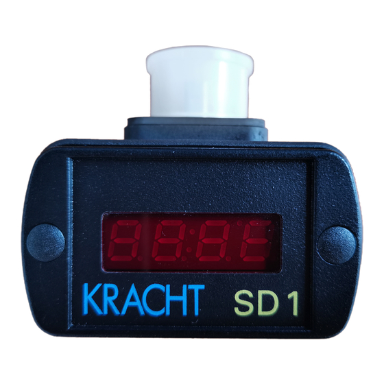
2. Description The plug-in display unit SD 1 may be used with any KRACHT volume counter which uses a plug-in connection according to DIN 43650. The display unit is simply inserted between the plug and the plug socket on the volume counter. -
Page 5: Connecting The Sd1
The square wave pulses are displaced from one another by 90°. It is therefore possible to detect the direction. This is referred to as a two channel layout. If the SD 1 works with a volume counter, which has only 1 sensor, it is a 1-channel version. Connection on clamp (channel 2) is not necessary. -
Page 6: Connecting The Sd1 With Analog Output
3.3 Connecting the SD1 with analog output The SD1 is available in 3 versions SD1-R with two rectangular signals with a pulse offset of 90°, SD1-I with analog output (0-20 mA/4-20 mA), SD1-K with relay contact. Connections are different in every serial-model modification. Option with analog output (0-20mA/4-20 mA): Connection of analog output has to be made on clamps. -
Page 7: Connecting The Sd1 With Relay Contacts
3.4 Connecting the SD1 with relay contacts. The SD1 is available in 3 models: SD1-R with two rectangular signals with a pulse offset of 90°, SD1-I with analog output (0-20 mA/4-20 mA), SD1-K with relay contact. Connections are different in every serial-model modification. Option with relay contact: The SD1 has two relay contacts. -
Page 8: How Is The Flow Rate Measurement Activated
3.5 How is the flow rate measurement activated ? The SD1 can be switched to flow measurement or volume measurement. This will be made by programming SD1 under menu “7” at step “display”. The flow rate will be adjusted by “0” and the volume by “1”. (see 4.1 for overview of input values). -
Page 9: How Is The Volume Measurement Activated
3.6 How is the volume measurement activated ? The SD1 can be switched to flow measurement or volume measurement. This will be made by programming SD1 under menu “7” at step “display”. The flow rate will be adjusted by “0” and the volume by “1”. (see 4.1 for overview of input values). -
Page 10: Error Display
3.7 Error display On two channel volume counters it is possible to monitor the correct pulse sequence on the channels. Faulty pulses are not counted and thus do not change the volume measurement. If an error is established by the SD1, the character sequence “FAUL“ appears in the display. -
Page 11: Sd1 Programming
4. SD1 programming Each time the SD1 is to be operated, it is necessary to adapt the unit to the volume counter that is connected. Input procedure: The input procedure is the same for all input values and is therefore described once only. -
Page 12: Overview Of The Input Values
4.1 Overview of the input values The values which are required to be set can be inserted in the column labelled “Input value-User”. Menu – Input value - Standard Function Unit Reference User setting 0.040 Pulse volume of volume counter 3.500 Maximum value Analogue output 0.400... -
Page 13: What Must Be Programmed When Connecting A Volume Counter
“00 - pulse volume counter”, menu reference “09 - density”, and under menu reference “08” at the position “counter input”. The pulse volumes for KRACHT Volume counters can be obtained from the Table. The “X” characters in the “Input value Menu reference 08“ column are of no significance in setting the volume counter. -
Page 14: How To Change Time On Flow Display
4.3 How to change time on flow display ? You can choose between second, minute and hour to change time on flow display by adjusting menu 07. Setting the time base: Time base Input value Menu reference 07 Minutes XX00 Minutes XX10 Seconds... -
Page 15: How To Find Out The Flow Rate
4.4 How to find out the flow rate? The SD1 commands two measuring systems to determine the flow: n duration of period or measurement of pulse width and n gate time. You can choose between “gate time measurement” or “ duration of period measurement”... -
Page 16: What Must Be Programmed When Connecting The Relay Outputs
4.5 What must be programmed when connecting the relay outputs ? Relay function can be adjusted only if the instrument was ordered with option relay contacts (SD1-K.). The relays can be allocated to flow rate or volume measurement. Flow rate measurement A “0”... -
Page 17: What Must Be Programmed When Connecting The Analogue Output
4.6 What must be programmed when connecting the analogue output ? The analog output can be used only if the instrument was ordered with analog output (SD1-I...). The analogue output can be assigned to flow rate or volume measurement. Flow rate measurement A “0”... -
Page 18: Technical Data
5. Technical Data PIC 17C42 Processor Power pack 18 VDC – 28 VDC optional 10 – 19 VDC Supply ca. 120 mA Maximum input current General data Principle : 7 Segment LED, 7,62 mm, red Display Display :0.000 ... 9999 with floating point overrun ( >9999 ) : display 9999 Control keys Two keys behind the front cover... -
Page 19: Type Code
6. Type code Example : SD1 - R - 24 / . Identification for programs volume measurement only with version SD1-I or SD1-K; volume measurement with SD1-R on request. 24 VDC Power supply 12 VDC Power supply Square wave signals (incremental signal) Current output 0-20 mA, 4-20 mA Relay outputs BSD1-xxxP-06.99-GB... -
Page 20: Connections
7. Connections The electrical connections are made by a plug-connection DIN 43650 Connections Version SD1-R-24 PIN 1 = UB+ PIN 2 = GND PIN 3 = Channel 1 = Channel 2 Connections Version SD1-I-24 PIN 1 = UB+ PIN 2 = GND PIN 3 = Analogue output 0/4-20 mA...
Need help?
Do you have a question about the SD 1 and is the answer not in the manual?
Questions and answers