Table of Contents
Advertisement
Installation, Start-Up, and Operating Instructions
Downflow/Horizontal Gas Fired
Induced-Combustion Furnaces
Sizes 050 thru 135 Series C
NOTE: Read the entire instruction manual before starting the installation.
Index
SAFETY CONSIDERATIONS.....................................................................................................................................................................................2
Clearances From Combustible Materials.................................................................................................................................................................2
INTRODUCTION ......................................................................................................................................................................................................2-3
Dimensional Drawing...............................................................................................................................................................................................3
LOCATION ................................................................................................................................................................................................................3-4
General ..................................................................................................................................................................................................................3-4
Location Relative to Cooling Equipment.............................................................................................................................................................3-4
Hazardous Locations ................................................................................................................................................................................................4
AIR FOR COMBUSTION AND VENTILATION ..................................................................................................................................................4-6
Unconfined Space.....................................................................................................................................................................................................4
Confined Space .....................................................................................................................................................................................................4-6
SUPPLY-AIR PLENUM INSTALLATION (DOWNFLOW).....................................................................................................................................6
Installation On a Concrete Slab...............................................................................................................................................................................6
Installation On a Combustible Floor .......................................................................................................................................................................6
HORIZONTAL ATTIC INSTALLATION ..................................................................................................................................................................7
Construct a Working Platform.................................................................................................................................................................................7
Install Furnace ..........................................................................................................................................................................................................7
HORIZONTAL CRAWLSPACE INSTALLATION ................................................................................................................................................7-8
FILTER ARRANGEMENT.......................................................................................................................................................................................8-9
GAS PIPING ............................................................................................................................................................................................................9-10
ELECTRICAL CONNECTIONS ..........................................................................................................................................................................11-12
115-v Wiring ..........................................................................................................................................................................................................11
24-v Wiring ............................................................................................................................................................................................................11
Accessories ........................................................................................................................................................................................................11-12
VENTING ....................................................................................................................................................................................................................13
START-UP, ADJUSTMENT, AND SAFETY CHECK ......................................................................................................................................13-20
General....................................................................................................................................................................................................................13
Sequence Of Operation.....................................................................................................................................................................................13-15
Heating Mode .........................................................................................................................................................................................................13
Cooling Mode.........................................................................................................................................................................................................13
Continuous Blower Mode.................................................................................................................................................................................13-15
Heat Pump Mode....................................................................................................................................................................................................15
Start-up Procedures ................................................................................................................................................................................................15
Adjustments.......................................................................................................................................................................................................15-19
Check Safety Controls ......................................................................................................................................................................................19-20
Checklist .................................................................................................................................................................................................................20
Form: IM-GB3A-04
®
Cancels: IM-GB3A-03
ama
A PP R O VED
R
Printed in U.S.A.
4-94
GB3AAV
Catalog No. 92-33GB-3A5
Page
Advertisement
Table of Contents

Summary of Contents for Resco GB3AAV
-
Page 1: Table Of Contents
Installation, Start-Up, and Operating Instructions Downflow/Horizontal Gas Fired GB3AAV Induced-Combustion Furnaces Sizes 050 thru 135 Series C ® A PP R O VED NOTE: Read the entire instruction manual before starting the installation. Index Page SAFETY CONSIDERATIONS.....................................2 Clearances From Combustible Materials.................................2 INTRODUCTION ........................................2-3... -
Page 2: Safety Considerations
INTRODUCTION The model GB3AAV Series C Furnaces are available in sizes 50,000 through 135,000 Btuh input capacities. The design of the downflow/horizontal gas-fired furnace is A.G.A./C.G.A. certified for natural and propane gas and for installation on noncombustible flooring. -
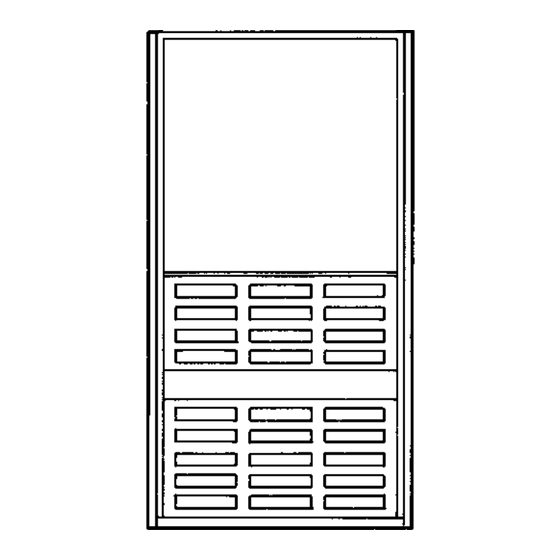
Page 3: Dimensional Drawing
A88324 Fig. 1—Dimensional Drawing Table 2—Dimensions (In.) UNIT SIZE VENT CONN SHIP. WT 024050 14-3/16 12-9/16 12-11/16 036050 14-3/16 12-9/16 12-11/16 024070 14-3/16 12-9/16 12-11/16 036070 14-3/16 12-9/16 12-11/16 036095 17-1/2 15-7/8 048095 17-1/2 15-7/8 048115 17-1/2 15-7/8 060115 19-3/8 19-1/2 060135 24-1/2... -
Page 4: Location Relative To Cooling Equipment
An unconfined space must have at least 50 cu ft for each 1000 Btuh of input for all the appliances (such as furnaces, clothes dryer, water heaters, etc.) in the space. For Example: MINIMUM SQ FT GB3AAV FURNACE WITH INPUT BTUH 7-1/2 FT CEILING... - Page 5 Each opening MUST have at least 1 sq in. of free area per 1000 Btuh of the total input for all equipment within the confined space, but not less than 100 sq in. per opening. (See Fig. 2.) For Example: GB3AAV FURNACE FREE AREA PER INPUT BTUH OPENING (SQ IN.)
-
Page 6: Supply-Air Plenum Installation (Downflow)
A & B C & D D & E F & G A93388 Fig. 3—Air for Combustion and Ventilation (Outside Air) For Example: GB3AAV FURNACE FREE AREA PER ROUND PIPE INPUT BTUH OPENING (SQ IN.) (IN. DIA) 46,000 23.0 69,000 34.3... -
Page 7: Horizontal Attic Installation
HOLE IN FLOOR A73382 Fig. 4—Floor Opening for Concrete Slab FURNACE PLENUM A73383 Fig. 5—Furnace on a Concrete Slab (Non-Garage Installation) PROCEDURE 4—HORIZONTAL ATTIC INSTALLATION WARNING: Do not install the furnace on its back; safety control operation will be adversely affected. Never connect return-air ducts to the sides or back of the furnace. -
Page 8: Filter Arrangement
FURNACE (OR COIL CASING WHEN USED) DOWNFLOW SUBBASE SHEET METAL PLENUM A78651 Fig. 6—Furnace, Plenum, and Subbase Installed on a Combustible Floor LINE CONTACT ONLY PERMISSIBLE BETWEEN LINES FORMED BY INTERSECTIONS OF THE TOP AND TWO SIDES OF THE FURNACE JACKET AND BUILDING JOISTS, STUDS, OR FRAMING. -
Page 9: Gas Piping
AIRFLOW 12″ 4″ FIELD-SUPPLIED FILTER RETAINERS A82173 Fig. 8—Horizontal Filter Arrangement Table 4—Filter Retainer (In.) FURNACE FILTER SIZE CASING WIDTH AND QUANTITY 14-3/16 (2) 14 X 20 X 1 14-3/8 17-1/2 (2) 14 X 20 X 1 13-3/8 (2) 16 X 20 X 1 11-5/8 24-1/2 (2) 16 X 20 X 1... - Page 10 Table 5—Maximum Capacity of Pipe * NOMINAL LENGTH OF PIPE (FT) INTERNAL IRON PIPE DIAMETER (IN.) SIZE (IN.) 0.622 0.824 1.049 1-1/4 1.380 1400 1-1/2 1.610 2100 1460 1180 → Ref: Table 10-2 NFPA 54/ANSI Z223.1-1992. * Cubic ft of gas per hr for gas pressures of 0.5 psig (14-in. wc) or less, and a pressure drop of 0.5-in. wc (based on a 0.60 specific gravity gas). CAUTION: If a flexible connector is required or allowed by the authority having jurisdiction, black iron pipe shall be installed at the gas valve and extend a minimum of 2 in.
-
Page 11: Electrical Connections
PROCEDURE 8—ELECTRICAL CONNECTIONS A. 115-v Wiring Refer to the unit rating plate or Table 6 for equipment electrical requirements. The control system requires an earth ground for proper operation. CAUTION: Do not connect aluminum wire between disconnect switch and furnace. Use only copper wire. Make all electrical connections in accordance with the current edition of the National Electrical Code (NEC) ANSI/NFPA 70-1993, and any local codes or ordinances that might apply. - Page 12 A93053 → Fig. 12—EAC Terminals on Control Board FIELD 24-VOLT WIRING FIELD 115-, 208/230-, 460-VOLT WIRING FACTORY 24-VOLT WIRING FACTORY 115-VOLT WIRING THERMOSTAT FOUR FIELD-SUPPLIED TERMINALS WIRE FUSED DISCONNECT TWO-WIRE 208/230- OR HEATING- 460-VOLT ONLY THREE PHASE 208/230- VOLT SINGLE AUXILIARY 115-VOLT FIELD- PHASE...
-
Page 13: Venting
PROCEDURE 9—VENTING Refer to the enclosed Installation Instructions, GAMA Venting Tables for Category I Furnaces and RESCO Tables for Category I Fan-Assisted Furnaces. The horizontal portion of the venting system shall maintain a minimum of 1/4-in. upward slope per linear ft and it shall be rigidly supported every 5 ft or less with hangers or straps to ensure that there will be no movement after installation. - Page 14 —14—...
-
Page 15: Heat Pump Mode
(2.) Obtain average yearly specific gravity for local gas supply. (3.) Verify furnace model. Table 7 can only be used for model GB3AAV Furnaces. (4.) Check and verify orifice size in furnace. NEVER ASSUME THE ORIFICE SIZE. ALWAYS CHECK AND VERIFY. - Page 16 Table 7—Model GB3AAV Orifice Size and Manifold Pressure for Correct Input Rate* (Tabulated Data Based on Altitude Up to 2000 ft and 23,000 Btuh Per Burner) SPECIFIC GRAVITY OF NATURAL GAS GAS HEAT VALUE 0.56 0.58 0.60 0.62 0.64 0.66 0.68...
- Page 17 (1.) Obtain average yearly heat value for local gas supply. (2.) Check and verify orifice size in furnace. NEVER ASSUME THE ORIFICE SIZE. ALWAYS CHECK AND VERIFY. (3.) Turn off all other gas appliances and pilots. (4.) Start furnace and let run for 3 minutes. (5.) Measure time (in sec) for gas meter to complete 1 revolution.
- Page 18 A89020 Fig. 16—Burner Flame Table 8—Gas Rate (Cu Ft/Hr) SIZE OF TEST DIAL SIZE OF TEST DIAL SECONDS SECONDS FOR 1 FOR 1 REVOLUTION REVOLUTION cu ft cu ft cu ft cu ft cu ft cu ft 1800 1636 1500 1385 1286 1200...
-
Page 19: Check Safety Controls
Table 9—Canadian Orifice Size HIGH ALTITUDE SEA LEVEL 0-2000 FT 2000-4500 FT Natural Propane c. Adjust air temperature rise by adjusting blower speed. Increase blower speed to reduce temperature rise. Decrease blower speed to increase temperature rise. WARNING: Disconnect the electrical power before changing the speed tap. Failure to follow this warning could result in personal injury. -
Page 20: Checklist
4. Cycle test furnace with room thermostat. 5. Check operation of accessories per manufacturer’s instructions. 6. Review User’s Manual with owner. 7. Leave literature packet near furnace. —20— © 1994 RESCO P.O. Box 1667, Indianapolis, IN 46206 45003r Catalog No. 92-33GB-3A5...
Need help?
Do you have a question about the GB3AAV and is the answer not in the manual?
Questions and answers