Table of Contents
Advertisement
Table of Contents
Table of Contents ......................................................................................................... 1
1 About this manual ..................................................................................................... 3
1.1 Validity ................................................................................................... 3
1.2 Target group .......................................................................................... 3
1.3 Retention of the manuals ...................................................................... 3
1.4 CE marking ............................................................................................ 3
2 Safety instructions and regulations ......................................................................... 4
2.1 Technical rules ....................................................................................... 4
2.2 Accident prevention regulations .......................................................... 4
3 Unpacking .................................................................................................................. 5
3.1 Scope of delivery .................................................................................... 5
3.2 Check for transport damage ................................................................ 5
4 Technical data ........................................................................................................... 6
4.1 DC input data......................................................................................... 6
4.2 Output data ............................................................................................ 6
4.3 Efficiency and safety equipment .......................................................... 7
4.4 General data ........................................................................................... 7
5 Installation and startup ............................................................................................ 8
5.1 Selecting an appropriate place for installation ................................... 8
5.1.1 Dimensions and weight ................................................................................ 8
5.1.2 Ambient conditions ...................................................................................... 9
5.1.3 Position ....................................................................................................... 10
Installation Instructions
1
Advertisement
Table of Contents

Summary of Contents for Eversolar Eversol-TL2100
-
Page 1: Table Of Contents
Table of Contents Table of Contents ......................1 1 About this manual ..................... 3 1.1 Validity ....................3 1.2 Target group ..................3 1.3 Retention of the manuals ..............3 1.4 CE marking .................... 3 2 Safety instructions and regulations ................. 4 2.1 Technical rules .................. - Page 2 5.2 Installing the inverter ................10 5.3 Electrical connection ................13 5.3.1 Connection to the public grid (AC) ............14 5.3.2 Connection to the PV generator (DC) ............20 5.4 Startup ....................23 5.5 Communication ................... 23 5.5.1 Communication through RS232 ..............23 5.5.2 Communication through RS485 ..............
-
Page 3: About This Manual
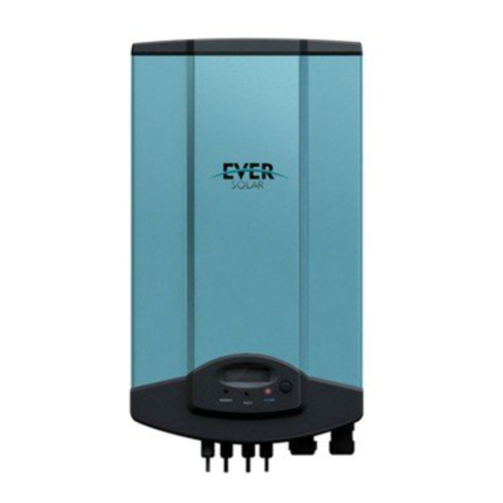
1 About this manual 1.1 Validity This installation instructions describes the installation and startup of Eversolar New Energy inverters of the type Eversol-TL2100, Eversol-TL3200, Eversol-TL4600, Eversol-TL5400. 1.2 Target group Only an authorized skilled electrician who is approved by the supply grid operator may install and startup the inverter. -
Page 4: Safety Instructions And Regulations
2 Safety instructions and regulations 2.1 Technical rules Installation must be suited to the on-site conditions and comply with local regulations and technical rules. 2.2 Accident prevention regulations 1. Only skilled electricians who have read and fully understood all safety information contained in these operating and installation instructions, may install the inverter. -
Page 5: Unpacking
3 Unpacking 3.1 Scope of delivery Object Description Quantity Eversol inverter 1 pcs Ornamental plate 1 pcs MC IV-connectors including male 2 pairs (for TL4600 and TL5400) connector and female connector 1 pair (for TL2100 and TL3200) AC connector 1 pcs Installation and operating 2 pcs instructions... -
Page 6: Technical Data
4 Technical data 4.1 DC input data Type TL 2100 TL 3200 TL 4600 TL 5400 Max. PV-generator power [W] 2100 3200 4600 5400 Max. DC Voltage [V] MPPT voltage range [V] 125 - 530 125 - 530 125 - 550 125 - 550 Turn off DC Voltage [V] Max. -
Page 7: Efficiency And Safety Equipment
4.3 Efficiency and safety equipment Type TL 2100 TL 3200 TL 4600 TL 5400 Efficiency Max. efficiency 97.1% 97.3% 97.5% 97.5% Euro efficiency (at 360VDC) 96.5% 96.5% 97.0% 97.0% MPPT adaptation efficiency 99.5% 99.5% 99.5% 99.5% Safety equipment Internal overvoltage protection Integrated DC Insulation monitoring Integrated... -
Page 8: Installation And Startup
5 Installation and startup 5.1 Selecting an appropriate place for installation Danger! Danger of lethal injury due to fire or explosion! The Eversol may become hot in normal operation. Do not install the Eversol on flammable construction materials and where flammable materials are stored. Do not install the Eversol in areas where there is a risk of explosion. -
Page 9: Ambient Conditions
Type Eversol-TL2100 Eversol-TL3200 Eversol-TL4600 Eversol-TL5400 Weight 19.9 kg 20.7 kg 21.4 kg 23.5 kg 5.1.2 Ambient conditions 1. The area where the units installed is as dry as possible in order to extend their service life. 2. Ensure good access to the unit for installation or any service work that may later be required. -
Page 10: Position
5.1.3 Position 1. The unit has been designed for vertical or tilted backwards by max. 15° installation. 2. Do not install the Eversol forwards. 3. Never install it horizontally. 4. Installing at eye level makes it easier to operate and read the display. 5.2 Installing the inverter Installing procedure: a) Drilling holes... - Page 11 b) Wring the screws After drilling holes in the wall, place four expansion tubes (object 2 shown in the left drawing below) in the holes using a rubber hammer. Then, wring two screws (object 1) into the top expansion tubes. The other two screws must wring into the two expansion tubes below with two washers.
- Page 12 c) Attach the Eversol to the screws slightly downwards. Installation Instructions...
-
Page 13: Electrical Connection
d) Check both sides for correct positioning and then tighten the four screws. 5.3 Electrical connection Installation Instructions... -
Page 14: Connection To The Public Grid (Ac)
After remove the ornamental plate and connection cover, the plug connectors show above. Object Description DC input: Plug connectors for connecting the PV modules. Their polarity is positive, negative, negative and positive terminals, respectively, which are signed in the front of the inverter. Communication connecting area. - Page 15 Connection Procedure by the connector 1: 1. Switch off the breaker and secure against being inadvertently switched back on. 2. Prepare the cable and bare the ends of each wire as shown in the figure (in mm). 3. Screw off every component of AC connector and pull the cable (three wires including L, N and PE) through those components as shown in the figure below.
- Page 16 Disconnect the wires: Wire L Hole L Wire N Hole N Wire PE Hole 4. After fasten the three wires with the terminal, combine every component together. Close the connector: Open the connector: Installation Instructions...
- Page 17 5. Finally, connect the AC connector to the AC terminal on the inverter. Pay attention to the polarity of the terminals avoid wrong connecting. Lock the housing: Unlock the housing: Installation Instructions...
- Page 18 Connection procedure by the connector 2: 1. Switch off the breaker and secure against being inadvertently switched back on. 2. Prepare the cable and bare the wire ends 7mm. 3. Screw off every component of AC connector as shown in the figure below. Straight Plug Grommet Adapter Assy...
- Page 19 6. Aim the terminals on the straight plug to the holes of the grommet, and then compress them together. After that tighten the adapter assy, gland body and screw cap in turn with a wrench. 7. Finally, connect the straight plug to the AC terminal on inverter. Pay attention to the polarity of the terminals avoid wrong connecting.
-
Page 20: Connection To The Pv Generator (Dc)
5.3.2 Connection to the PV generator (DC) Attention! In order to safeguard the installation and startup of the device, a manual circuit breaker must be configured on the DC side out of the inverter. The breaker should have certain capacity of over current and overvoltage. - Page 21 5. Please use professional tools to disassemble the connectors. Type Maximum input voltage Maximum input current Eversol-TL2100 580 V 18 A Eversol-TL3200 580 V 20 A...
- Page 22 Connection Procedure: 1. Switch off the circuit breaker and secure against being inadvertently switched back on. Prepare the cable and bare the end with a stripping pliers as shown below. 6 mm 3. Connect the cable together with MC IV connector. ...
-
Page 23: Startup
If the inverter is in “Fault” state, look over the FAQ part in operating manual. 5.5 Communication A PV system with inverters can be monitored in different ways. Eversolar New Energy provides you RS232 and RS485. 5.5.1 Communication through RS232 The current data of the PV inverter can be transmitted to PC through RS232 interface. - Page 24 updated via RS232. Because an inverter can only communicate with one PC through RS232 at the same time, this communication method is usually used during updating the software。 The definition of the pins of RS232: Pin1--------NC Pin2--------TX Pin3--------RX Pin4--------NC Pin5--------GND Pin6--------NC Pin8--------NC Pin7--------NC...
-
Page 25: Communication Through Rs485
5.5.2 Communication through RS485 RS485 is used for multipoint communication. Up to 50 inverters can communicate and be monitored through one cable. But the maximum length of the cable should not surpass 1000 m. All the inverters, which communicate through one cable, should use the provided RS485 interface. - Page 26 The definition of the pins of RS485 for Eversol-TL series: Pin1------- TX_RS485A Pin2-------TX_RS485B Pin3-------RX_RS485A Pin4-------GND Pin5-------GND Pin6-------RX_RS485B Pin7-------+7V Pin8-------+7V Connection procedure: 1. Pull RS485 cable through three components below including gland body, sealing insert plug and dome nut, and screw down. We provide you plugs with no hole, one hole and two holes.
- Page 27 2. A RS485 cable is composed by eight wires with different color. Cut off outside envelope to reveal the eight wires. Then make the end of every wire straight, and put them in order. The connection between crystal connectors and RS485 wires is one-to-one correspondence, one pin of crystal connector to one specific color wire, as shown in the table below.
-
Page 28: Safety Protection
4. Connect the other end of RS485 cable to crystal connector by repeating the procedure 3 and 4. 5. The inverter can connect with a PMU by a RS485 cable at both ends with a crystal connector. After the PMU connects with PC by Ethernet or USB, the inverter can communicate with PC. -
Page 29: Ground Fault Current Interruption (Gfci)
The inverter is intended to be used under +60 C. When the temperature reaches 70 power is derating and derating to zero as it up to 85 C. When the heat peak temperature has decreased, the inverter starts up again automatically. 5.6.3 Ground fault current interruption (GFCI) AC/DC-sensitive residual current device monitors the leakage and residual current from the inverter’s grid connection to the PV generator and disconnects the circuit... -
Page 30: Contact
6 Contact If you have technical problems about our product, you can contact us via: www. ever-solar.com ADD: Building 9 No. 198 Xiangyang Road, CN-215011 Suzhou, China Tel.: +86 512 6937 0998 Fax: +86 512 6937 0630 Email: service@ever-solar.com Installation Instructions...
Need help?
Do you have a question about the Eversol-TL2100 and is the answer not in the manual?
Questions and answers