Table of Contents
Advertisement
Quick Links
A Family Company Manufacturing
In The USA Since 1969
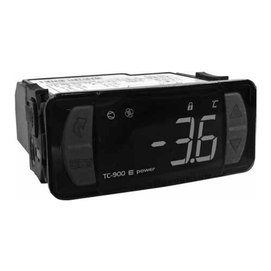
D
ixell
D
C
o
igital
ontroller
peration
This manual is specific to the operation and diagnostic
guides of the Dixell digital controller used in Glastender
self-contained back bar coolers.
Dixell
To view the manual specific to the Full Gauge digital controller used in Glastender
self-contained back bar coolers visit:
http://www.glastender.com/PDF/Full_Gauge_digital_controller_operation.pdf
Full Gauge
Glastender, Inc. · 5400 North Michigan Road · Saginaw, MI · 48604-9780
800.748.0423 · 989.752.4275 · Fax 989.752.4444 · www.glastender.com
11-02-17
© 2017 Glastender, Inc.
Advertisement
Table of Contents

Summary of Contents for Glastender Dixell
- Page 1 This manual is specific to the operation and diagnostic guides of the Dixell digital controller used in Glastender self-contained back bar coolers. Dixell To view the manual specific to the Full Gauge digital controller used in Glastender self-contained back bar coolers visit: http://www.glastender.com/PDF/Full_Gauge_digital_controller_operation.pdf Full Gauge Glastender, Inc.
- Page 2 Service calls to reconnect the probe wiring are not covered by factory warranty. Glastender, Inc. • 5400 North Michigan Road • Saginaw, MI • 48604-9780 800.748.0423 • 989.752.4275 • Fax 989.752.4444 • www.glastender.com Rev. 11-11-14...
- Page 3 Warning: Performance and reliability issues that result from the controller parameters being changed from the factory default settings are not covered under warranty. Controller error codes: ➢ P1- Room Probe Failure • Check to make sure the probe is connected to the controller •...
- Page 4 Checking the controller display temperature accuracy: ➢ After verifying the probe resistance to the box temperature, plug the probe into the controller and check the temperature displayed The controller should display the associated temperature of Table 1 above when compared to the •...
- Page 5 Diagnostic flow charts: Is the box temp cycling at the Is the “AU” Set point Does the probe resistance set point plus the differential? programmed for factory default? match the associated See Checking the controller See Resetting the program to temperature of Table 1? Set point factory default settings...
Need help?
Do you have a question about the Dixell and is the answer not in the manual?
Questions and answers