
Related Manuals for Niles IntelliPad Ci


Summary of Contents for Niles IntelliPad Ci
- Page 1 I I n n t t e e l l l l i i P P a a d d C C i i ® IntelliPad Ci ® IntelliPad Ci K K E E Y Y P P A A D D I I N N S S T T A A L L L L A A T T I I O O N N G G U U I I D D E E...
-
Page 2: Table Of Contents
Accessory Keypad Module ............3 ™ PARTS GUIDE ....................5 INSTALLATION CONSIDERATIONS ............7 Where to Mount an IntelliPad Ci Keypad..........7 Choosing between Electrical Boxes or P-Rings .......... 7 INSTALLATION .................... 9 Overview ....................9 Installing the Master Key Labels .............. 10 Installing the Keypad Modules .............. -
Page 3: Introduction
Accessory Keypad Modules. All programming, connection and operation information is detailed in the Niles MultiZone Control System Installation and Operation Guide. : Not all IntelliPad Ci Keypad Modules work with all Niles MultiZone Systems; Important Note refer to the MultiZone Control Systems Installation and Operation Guide for specific keypad compatibility. -
Page 4: Solo Master Keypad Module
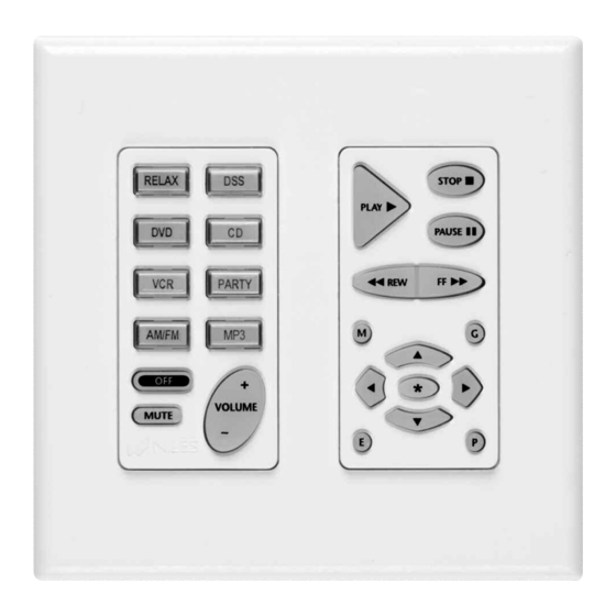
® N T E L L I E Y P A D O D U L E S Solo Master Keypad Module The Solo (See Figure 1) is one of two Master Keypad Modules available. It was designed to operate alone, or in conjunction with a Numeric Accessory Keypad Module (See Figure 3). - Page 5 ® N T E L L I E Y P A D O D U L E S AM/FM RELAX RELAX PARTY AM/FM VOLUME VOLUME MUTE MUTE Figure 1 Figure 2 Solo Master Keypad Module Select Master Keypad Module TUNER STOP PLAY PAUSE...
-
Page 6: Parts Guide
Back View: Solo/Select and Numeric/Transport (a) IR Sensor: RJ-45 connector for connection of IR Sensors (use the Niles RJ-45 to three wire adapter, for IR Sensors wired with two-conductor shielded cable. (b) System: RJ-45 connector for connection to a Niles MultiZone System. -
Page 7: Installation Considerations
CAUTION: Do not install the IntelliPad Ci into electrical boxes with 110 volt devices. Some states or municipalities allow devices such as the IntelliPad Ci Keypads to be installed into the same electrical box as 110 volts devices, provided a “low-voltage partition” is used between the devices. -
Page 8: Choosing Between Electrical Boxes Or P-Rings
O D U L E S Choosing between Electrical Boxes or P-Rings The mounting depth of the IntelliPad Ci Keypad Module is 2-1/2”. When installed, the unit extends 2” behind the sheetrock wall (assuming 1/2” sheetrock). Depending on how many Keypad Modules you are installing in a room, you can choose from a single-gang to a four-gang standard light switch plaster ring (p-ring) or a standard 36 cubic in. - Page 9 ® N T E L L I E Y P A D O D U L E S Figure 5 (a) Electrical box (J-box) (b) Four pair twisted cable (c) Solo Master Keypad Module (d) Numeric Accessory Keypad Module (e) Master Keys (f) Function Keys (g) Device screws (4 supplied) (h) Solo Master Keypad Module...
-
Page 10: Installation
4. Install the Master Key Labels (refer to Installing the Master Key Labels in this manual for more information). 5. Make all cable connections to all Keypads and IR Sensors (refer to the Niles MultiZone System Installation and Operation Guide for more information). -
Page 11: Installing The Master Key Labels
4. Remove all plastic key caps from the elastomer as shown in Figure 7. Place them next to the labels. 5. If you are installing an Intellipad Ci Silencer along with a Master Keypad Module, replace the original elastomer from the Master Keypad Module with the appropriate elastomer for the Keypad Module you are installing as shown in Figure 8. - Page 12 ® N T E L L I E Y P A D O D U L E S Figure 6 Figure 7 Figure 8 Removing the insert. Removing key caps. Replacing the elastomer. Figure 9 Figure 10 Figure 11 Dropping in labels. Replacing key caps.
- Page 13 ® N T E L L I E Y P A D O D U L E S 9. To re-install the appropriate Decora style insert, hold the Keypad Module chassis so that it is facing you as shown in Figure 11. Fit the insert around the keys of the Keypad Module.
-
Page 14: Installing The Keypad Modules
Systems Installation and Operation Guide for instructions) 6. If installing an IntelliPad Ci Silencer, it should always be placed furthest to the right in the J-box or P-ring, because it only has one jack. (Keypad Modules have an IN and an OUT jack.) -
Page 15: Installing The Decora Cover Plate
® N T E L L I E Y P A D O D U L E S Securing the Keypad Modules 1. Insert the included 1–1/4” long device screws into the oblong-shaped screw holes on the top and bottom of the Keypad Module. NOTE: The oblong shape of the screw holes allows you to position the Keypad Module so that it is vertical. -
Page 16: Operation
® N T E L L I E Y P A D O D U L E S OPERATION Refer to the Niles MultiZone Control System’s Manual for information on how to operate the Keypad Modules once installed. -
Page 17: Specifications
Up to 500 feet of individually home-run four pair twisted cable (CAT3 or CAT 5). Or, up to 500 feet of individually home-run 22 gauge two-conductor, shielded cable (West Penn D291 or equivalent). NOTE: A Niles Adapter (FG00852) is required to connect an IR Sensor when using two conductor shielded cable. FCC CERTIFICATION Class “B”... - Page 18 Miami, Florida 33186 Tel: (305) 238-4373 ©2006 Niles Audio Corporation. All rights reserved. Niles, the Niles logo and IntelliPad are registered trade- marks of Niles Audio Corporation. Decora is a registered trademark of Leviton Manufacturing Company. All Fax: (305) 238-0185...
Need help?
Do you have a question about the IntelliPad Ci and is the answer not in the manual?
Questions and answers