
Subscribe to Our Youtube Channel
Related Manuals for NSK EDD Megatorque Motor


Summary of Contents for NSK EDD Megatorque Motor
- Page 1 MEGATORQUE MOTOR SYSTEM User’s Manual (Driver Unit Model EDD) M-E099DD0C2-201 Document Number: C20201-01...
- Page 2 Ltd. is notified of in writing within, which comes first, one (1) year of shipment or 2400 total operation hours. NSK Ltd., at its option, and with transportation charges prepaid by the claimant, will repair or replace any product which has been proved to the satisfaction of NSK Ltd. to have a defect in material and/or workmanship.
- Page 3 Notes for Proper Use of Megatorque Motor System 1. For Safety Use of the Products This product is intended for the uses of general industry, and is not designed and/or manufactured for the uses involving human lives. When you consider to use this product for special uses such as nuclear control, aero-space devices, traffic control, medical devices, various safety devices or such systems, please contact us.
- Page 4 3. Precautionary statement for the prolonged use of the Motor 1) Temperature Keep the ambient temperature of the Motor within 0 to 40[°C]. You cannot use the Motor in a high temperature atmosphere over 40[°C]. 2) Dust-proof and Waterproof of the Motor ...
- Page 5 4. Quick troubleshooting …Confirm it one more time. 1) When an alarm occurs When an alarm occurs right after the power is on, please refer to 4.1. Quick Troubleshooting…Alarm when the power is on . Did you take proper action to the alarm? ◊...
- Page 6 4.1. Quick Troubleshooting…Alarm when the power is on The alarm occurs when the power is turned on if input signals of EMST (Emergency stop, Pin No.3) and OTP/OTM (Over travel limits, Pin No. 5 and 6) of the connector CN2 are not connected. However, the Driver Unit is not defective.
- Page 7 Step 2: Polarity setting of Input ports. 1) Input the command MO (Motor Off) to make the Motor servo off to set the polarity of control inputs. 2) Input the command PI0 (Edit input function). :PI0 FNEMST;_ 3) Following the display of the parameter FN FNEMST;...
- Page 8 (Blank Page)
- Page 9 Conformity with EMC Directive NSK defined installation models (conditions) for the Megatorque Motor PS/PN Series, including installation space and wiring between Driver Units and Motors, and set EMC Directive based on 4 [m] cable models, which have been certified by TÜV SÜD Product Service GmbH.
- Page 10 Conditions to Conform with EU Directives The wiring example shown below is one of our recommendations for the conformity with the EU Directives. Figure 1: Wiring diagram (Example) Inside of control panel Driver Unit Model EDD AC power source Noise filter Circuit breaker Control power...
- Page 11 Conformity with Underwriters Laboratories Standards Motors Motor is compliant with UL1004-1 standard. (File number:E216970) Driver Unit Model EDD Driver Unit Model EDD is compliant with UL61800-5-1 standard. (File number:E216221) Cable set The cable material which is conforming to UL standard is used. Be sure to meet the following as they are the supplementary conditions for the qualification.
- Page 12 ! Danger : Megatorque Motor PN series with Brake unit, Megatorque Motor Z series with High environmental resistance, Megatorque Motor High speed PX series with its Driver Unit, and their system as a combination of Motor and Driver Unit do not comply with UL and CE marking regulation.
-
Page 13: Table Of Contents
Contents 2.10.1.2. CN2 Signal List ------------------------- 2-31 1. Introduction ------------------------------------ 1-1 2.10.2. CN2 Interfacing --------------------------------- 2-33 1.1. Notes to Users --------------------------------------------- 1-2 2.10.2.1. General Input Signal ------------------- 2-33 1.1.1. Notes for Safety ----------------------------------- 1-2 2.10.2.2. Pulse Train Input Signal -------------- 2-34 1.1.2. - Page 14 4.1.4. Monitoring the Current Status ------------------ 4-6 6.3.4.2. 6-30 Jogging via RS-232C Communication 4.1.4.1. Inputting a Command while 6.3.5. RS-232C Communication Positioning Monitoring Multiple Conditions ---------- 4-6 Operation ----------------------------------------- 6-31 4.2. USB Communication (EDD MEGATERM) ---------- 4-7 6.3.6. 6-33 Velocity and Torque Control by Analog Input 4.2.1.
- Page 15 7.4.2. Customization of Monitor Data --------------- 7-36 8.8. Home Return --------------------------------------------- 8-45 7.4.2.1. Analog Monitor for State of Control 8.8.1. Home Return Operation via the Inputs and Outputs Functions --------- 7-37 Home Position Sensor ------------------------ 8-46 8.8.1.1. Home Return Mode: OS4 -------------- 8-46 8.
- Page 16 10.4.2. Cables --------------------------------------------- 10-3 12.2.1. Power Trouble----------------------------------- 12-2 10.4.3. Driver Unit ---------------------------------------- 10-4 12.2.2. Motor Trouble ----------------------------------- 12-2 10.5. Repair Service ----------------------------------------- 10-6 12.2.3. Vibration, Abnormal Noise or Unstable Settling -------------------------------------------- 12-3 10.6. Warranty Period and Covering Range ----------- 10-7 12.2.4.
-
Page 17: Introduction
1. Introduction 1. Introduction This is the operation manual of the Megatorque Motor System with the Driver Unit Model EDD. Please refer to “2.4. Standard Combination List” for the applicable Megatorque Motor System. Before operating the Megatorque Motor System for the first time, this manual should be read thoroughly. ... -
Page 18: Notes To Users
1. Introduction 1.1. Notes to Users 1.1.1. Notes for Safety For your safety, you should read this manual thoroughly and understand the contents before operating the Megatorque Motor System. The following notices are added to give particular emphasis on the safety precautions in this manual. !... - Page 19 1. Introduction ! Caution : Use of an optional regeneration resistor shall be considered for a heavy- duty operation. • The Megatorque Motors regenerate when they decelerate carrying heavy load inertia. • An internal capacitor charges the Motor regeneration. However, when high and continuous regeneration exceeding its capacity is applied, excess energy activates an alarm “Alarm P1: Abnormal main power voltage”...
- Page 20 ] or less. (However, there may be a possibility to exceed the above limits in some cases. Please consult NSK when you require a close investigation on the limits.) • For the PN4180 Motor, be sure to stop the Motor for 20 minutes or longer when you stop it by the dynamic brake.
-
Page 21: Interchangeability Of Motor And Driver Unit
1. Introduction 1.1.3. Interchangeability of Motor and Driver Unit Interchangeable types The standard Motors and the Driver Units Model EDD can be randomly matched (interchangeable). Therefore, you may have a combination of a Motor and a Driver Unit that have the different serial number. -
Page 22: Terminology
1. Introduction 1.2. Terminology It is necessary to be familiar with some terms used in this document. Cable Set -------------- A cable set exclusive use for the Megatorque Motor System. Connects driver Unit and Megatorque Motor CCW ------------------- Counterclockwise; direction of Motor rotation. Seen from the top of rotor. ... -
Page 23: Specifications
2. Specifications 2. Specifications 2.1. System Configuration 2.1.1. Control Mode The Driver Unit Model EDD is compatible with 45 types of interface devices, and is capable of the operations described in “Table 2-1: Applicable interface and control mode.” Table 2-1: Applicable interface and control mode Applicable Control mode Controllers/Interfacing devices... -
Page 24: Examples Of System Configuration
2. Specifications 2.1.2. Examples of System Configuration Fig 2-1: System configuration for program operation Main power PLC* Single phase: 100 to 240 [VAC] Motor controller* Circuit breaker* Driver Unit Model EDD (MCCB) Noise filter* 24 VDC power supply* Magnetic contactor* (USB Megatorque Motor communication) - Page 25 2. Specifications Fig 2-3: System configuration for RS-232C serial communication command positioning Main power PLC* Single phase: 100 to 240 [VAC] Motor controller* Circuit breaker* Driver Unit Model EDD (MCCB) Noise filter* 24 VDC RS-232C power supply* communication Magnetic contactor* (USB Megatorque Motor communication)
-
Page 26: Reference Number And Coding
2. Specifications 2.2. Reference Number and Coding 2.2.1. Mega torque Motor Fig 2-4: Reference number coding of Mega torque Motor M-PS 1 006 K N 002 Megatorque Motor series Design number Motor size code N: No brake K: Incorporates absolute posiiton Motor maximum torque [N•m] sensor 2.2.2. -
Page 27: Name Of Each Part
2. Specifications 2.3. Name of Each Part 2.3.1. Mega torque Motor 2.3.1.1. PS Series Fig 2-8: PS series Megatorque Motor Hollow Dust cover (stationary part) Rotor (rotational part) Stator (stationary part) Mounting connector Resolver connector — 2-5 —... -
Page 28: Pn Series
2. Specifications 2.3.1.2. PN Series Fig 2-9: PN2012 Motor Hollow Cover (rotational part) (stationary part) Rotor (rotational part) Motor connector Mounting base Resolver connector Fig 2-10: PN3045, PN4135 and PN4180 Motors Hollow Cover (rotational part) (stationary part) Rotor (rotational part) Motor connector Resolver connector Mounting base... -
Page 29: Px Series
2. Specifications 2.3.1.3. PX Series Fig 2-11: PX3050 Motor Cover Hollow (stationary part) Rotor (rotational part) Motor connector Resolver connector — 2-7 —... -
Page 30: Driver Unit Model Edd
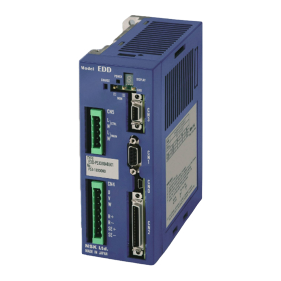
2. Specifications 2.3.2. Driver Unit Model EDD Fig 2-12: Driver Unit Model EDD (standard) (10) (12) (11) Heat sink (13) Power LED (7) Ground terminal M4 screws 7 segments LED (8) Type CN1 (9 pins) Reference number plate RS-232C serial communication cable connector Connect the optional Handy Terminal FHT31. -
Page 31: Handy Terminal
2. Specifications 2.3.3. Handy Terminal Fig 2-13: Handy Terminal M-FHT31 Frame : Escape key (Not used) Alphabetic keys Numeric keys Code keys (superscript) Special code keys Note 1) : Shift key SHIFT : Control key (Not used) CTRL Note 2) :... -
Page 32: Standard Combination List
2. Specifications 2.4. Standard Combination List 2.4.1. Motor and Driver Unit Model EDD Combinations Table 2-2: Motor and Driver Unit Model EDD Combinations Driver Unit Motor Motor Reference number Power Cable Remarks : code for specification of diameter reference number voltage[VAC] reference number included items. -
Page 33: Cable Set
2. Specifications 2.4.2. Cable Set Table 2-3: Reference Number of Cable Set Function Cable length [m] Cable set reference number M-C001SDP03 M-C002SDP03 M-C003SDP03 M-C004SDP03 M-C005SDP03 Stationary cable M-C006SDP03 M-C008SDP03 M-C010SDP03 M-C015SDP03 M-C020SDP03 M-C030SDP03 M-C001SDP13 M-C002SDP13 M-C003SDP13 M-C004SDP13 M-C005SDP13 Flexible cable M-C006SDP13 M-C008SDP13 M-C010SDP13... -
Page 34: Motor Specifications
2. Specifications 2.5. Motor Specifications 2.5.1. PS Series Table 2-5: Specifications of PS1 Motor Reference number M-PS1004KN510 M-PS1006KN002 M-PS1012KN002 M-PS1018KN002 Item [Unit] Motor outside diameter [mm] ø 100 [N•m] Maximum output torque 3 / 2 6 / 6 12 / 12 18 / 18 [N•m] Rated output torque... -
Page 35: Pn Series
2. Specifications 2.5.2. PN Series Table 2-7: Specifications of PN Motor Reference number M-PN2012KN201 M-PN3045KN001 M-PN4135KN001 M-PN4180KN001 Item [Unit] Motor outside diameter [mm] ø 170 ø 210 ø 280 [N•m] 12 / 10 45 / 45 Maximum output torque [N•m] Rated output torque 2 / 2 15 / 15... -
Page 36: Axial Load And Moment Load
2. Specifications 2.5.4. Axial Load and Moment Load ! Caution : Axial load Fa shall be less than to the allowance limits load. Radial load Fr shall be less than to the allowance limits load. Moment load M shall be less than to the allowance limits load. Fig 2-14: Load applied to a Motor (1) When F is the external force, then (2) When an extyernal force is F, then... -
Page 37: External Dimensions
2. Specifications 2.6. External Dimensions 2.6.1. Megatorque Motors 2.6.1.1. PS Series Fig 2-15 PS1004 type Motor 6-M4 × 0.7 depth 7 6-M4 × 0.7 depth 6 PCD92 (60° equal pitch) Rotation Part PCB45 (60° equal Do not use pitch) Resolver Connector Do not use Motor Connector... - Page 38 2. Specifications Fig 2-17: PS1012 type Motor 6-M4 × 0.7 depth 7 PCD92 (60° equal pitch) 6-M4 × 0.7 depth 6 PCD45 (60° equal pitch) Rotation Part Resolver Connector Motor Connector Rotor Shaft (rotation part) 5 or more Material: Aluminum Fixed Part Fig 2-18: PS1018 type Motor 6-M4 ×...
- Page 39 2. Specifications Fig 2-19: PS3015 type Motor Rotation Part depth 9 6-M6 × 1.0 depth 9 6-M6 × 1.0 depth 9 PCD139 (60° equal pitch) (C0.5) PCD69 (60° equal pitch) Resolver Connector Motor Connector Rotor (rotation part) Material: Aluminum 4 or more Fixed Part depth 8 (C0.5)
- Page 40 2. Specifications Fig 2-21: PS3060 type Motor Rotation Part depth 9 6-M6 × 1.0 depth 9 6-M6 × 1.0 depth 9 PCD139 (60° equal pitch) (C0.5) PCD69 (60° equal pitch) Resolver Connector Motor Connector Rotor (rotation part) Material: Aluminum 5 or more Fixed Part depth 8 (C0.5)
-
Page 41: Pn Series
2. Specifications 2.6.1.2. PN Series Fig 2-23: PN2012 type Motor 6-M5 depth 9 PCD120 (60° equal pitch) Tightening Torque: 5.3 to 6.5 Nm Screw Insertion Depth: 5 to 6.5 mm Motor Cable Resolver Cable Motor Connector Resolver Connector Nameplate Rotation Part Nameplate 7 through (Fixing Motor) - Page 42 2. Specifications Fig 2-25: PN4135 type Motor 6-M8 × 1.25 depth 12 depth 8 Nameplate PCD180 (60° equal pitch) (C0.5) 4.5 or more 5 or more (width of ø205 h8) Rotor (rotation part) Fixed Part Material: Aluminum Material: Iron 4-ø12 through Surface Treatment: Low Surface Treatment: N/A Nameplate...
-
Page 43: Px Series
2. Specifications 2.6.1.3. PX Series Fig 2-27: PX3050 type Motor 6-M5 × 0.8 depth 8 PCD151 (60° equal pitch) 6-M6 × 1.0 depth 9 7.5 or more 12-M5 × 0.8 depth 9 PCD69 (60° equal pitch) (width of ø105 h8) PCD94 (30°... -
Page 44: Driver Unit Model Edd
2. Specifications 2.6.2. Driver Unit Model EDD Fig 2-28: Driver Unit Model EDD (Motor type: PS1004, PS1006, PS1012, PS1018, PS3015, PS3030, and PN2012) Fig 2-29: Driver Unit Model EDD (Motor type: PS3060, PS3090, PN3045, PN4135, PN4180, and PX3050) — 2-22 —... -
Page 45: Cable Set
2. Specifications 2.6.3. Cable Set ! Caution : If you connect the cable to a moving part, be sure to use a flexible type cable. 2.6.3.1. Stationary Cable ! Caution : Bending radius of a Motor cable (ø 8) and resolver cable (ø 8) shall be R43 mm or over. - Page 46 2. Specifications Fig 2-31: Cable Set (Flexible type: M-C0×××SDP13) Motor Cable Resolver Cable — 2-24 —...
-
Page 47: Driver Unit Specifications
2. Specifications 2.7. Driver Unit Specifications Table 2-11: Specifications of Driver Unit Model EDD (PS Series) Item Specification Motor type PS1004 PS1006 PS1012 PS1018 PS3015 PS3030 PS3060 PS3090 Continuous output [Arms] Output current Maximum output [Arms] 14.9 14.9 Rated capacity [kVA] 0.45 Max. - Page 48 2. Specifications Table 2-12: Specifications of Driver Unit Model EDD (PN Series/PX Series) Item PN2012 PN3045 PN4135 PN4180 PX3050 Continuous output [Arms] Output current Maximum output [Arms] 14.9 14.9 14.9 14.9 Rated capacity [kVA] 4.8 / - 4.8 / - 4.5 / -...
-
Page 49: Usb Interface Specifications
2. Specifications 2.8. USB Interface Specifications ! Caution : Use a cable of 3 m or less for a connection cable with PC, etc. ! Caution : Be sure to connect a protective ground of the Driver Unit Model EDD. •... -
Page 50: Rs-232C Interface Specifications
Japan Aviation Electronics Industry, Ltd. DE-9PF-N* or equivalent Mating connector shell type DE-C2-J6R* or equivalent * The user shall provide these connectors. They are not necessary if NSK Handy Terminal FHT 21 is used. 2.9.1.1. CN1 Pin-Out Fig 2-33: Pin-out 2.9.1.2. -
Page 51: Specifications Of Control Input/Output Interface2-29
2. Specifications 2.10. Specifications of Control Input/Output Interface 2.10.1. CN2: Control Input/Output Signal Connector The connector and the mating connectors to be used for the CN2 connector are listed in the “Table 2-17: Connector list.” Table 2-17: Connector list Driver Unit connector DF02R050NA6 or equivalent Mating connector type... -
Page 52: Cn2 Pin-Out
2. Specifications 2.10.1.1. CN2 Pin-Out The pin-out for the CN2: Control Input/Output Signal Connector is shown in the “ Fig 2-34: Pin-out (shipping set).” For each port of CN2, assignment of Input/Output function can be changed. (Except for some ports) ... -
Page 53: Cn2 Signal List
2. Specifications 2.10.1.2. CN2 Signal List Table 2-18: Signal list (Shipping set) Input Port Signal Contact Signal name Function Output code code logic DC24 24 VDC external power supply External power supply for input signal DC24 24 VDC external power supply External power supply for input signal Terminates positioning operation and the Motor stops by the dynamic EMST... - Page 54 2. Specifications Table 2-19: Expanded function for function assignable control Input/Output Input Function code Function name Description Output Hold Pauses the Motor operation and execution of the program. Velocity override Changes the velocity command in a rate of the specified velocity. IOFF Integration OFF Terminates velocity integration control.
-
Page 55: Cn2 Interfacing
2. Specifications 2.10.2. CN2 Interfacing 2.10.2.1. General Input Signal Applied inputs: SVON, EMST, OTP, ACLR, PRG0 to PRG7, JOG, DIR, and STP Table 2-20: General specifications Item Specification Input voltage 24 VDC ± 10% Input impedance 3.9 k Maximum current 10 mA or less (per input) Fig 2-35: General specifications ※... -
Page 56: Pulse Train Input Signal
2. Specifications 2.10.2.2. Pulse Train Input Signal Applied inputs: CCWP +, CCWP -, CWP +, and CWP - Table 2-21: Pulse train input Item Specification Input voltage 5 VDC ±10% 620 Input impedance Maximum current 25 mA or less Fig 2-36: Pulse train input 620 ... -
Page 57: Analog Command Input Signal
2. Specifications 2.10.2.3. Analog Command Input Signal Applied output: AIN +, AIN - Table 2-22: Specifications of analog command input signal Item Specification Maximum input voltage ± 10 [VDC] 20 [kΩ] Input impedance Maximum input current 0.5 [mA] ADC resolution 12 [bit] Effective resolution 10 [bit] (Typ.) -
Page 58: Output Signal
2. Specifications 2.10.2.4. Output Signal Applied output: PO0 to PO7 (Shipping set: DRDY, WRN, OTPA, OTMA, SVST, BUSY, IPOS, and NEARA) Table 2-23: General output photo coupler specification Item Specification Maximum load capacity 24 VDC/50 mA Maximum saturated voltage 2 V or less Fig 2-40: General output photo coupler specification ~... -
Page 59: Analog Monitor Output
2. Specifications 2.10.2.6. Analog Monitor Output Applied output: MON1, MON2 Table 2-25: Analog monitor specification Item Specification Output format Op-amp Maximum output voltage Minimum voltage width 5.3 mV Saturated current 4 mA or less Fig 2-42: Analog monitor - MON1, 2 +... -
Page 60: Cn3: Resolver Cable Connector
2. Specifications 2.11. CN3: Resolver Cable Connector ! Caution : Connect the Cable Set provided with the Driver Unit. Do not cut or hookup to other cable because the Cable Set is uniquely made for the position sensor. Table 2-26: Connector list Driver Unit connector Japan Aviation Electronics Industry, Ltd. -
Page 61: Cn4: Motor Connector
2. Specifications 2.12. CN4: Motor Connector ! Caution : Use the Cable Set provided with the Driver Unit. Please do not cut the cable or hookup to other cable because the Cable Set is specially made for the position sensor. Table 2-28: Connector list Connector of Driver Unit PHOENIX CONTACT... -
Page 62: Cn5: Connector For Power Supply
2. Specifications 2.13. CN5: Connector for Power Supply The connectors for CN5 are shown in the Table 2-30: Connector list Table 2-30: Connector list Connector of Driver Unit PHOENIX CONTACT MSTBA2,5/5-G-5,08-LR or equivalent Mating connector PHOENIX CONTACT FKC 2,5/5-ST-5,08-LR or equivalent 2.13.1. -
Page 63: Unpacking, Installation And Wiring
3. Unpacking, Installation and Wiring 3. Unpacking, Installation and Wiring 3.1. Unpacking 3.1.1. Receiving Check Make sure you have received the following units. Megatorque Motor Driver Unit Cable Set (Motor and Resolver cable) 3.1.2. Motor and Driver Unit Model EDD Combinations !... -
Page 64: Installation
3. Unpacking, Installation and Wiring 3.2. Installation 3.2.1. Motor Mounting Please follow the notes described below to make full use of the capabilities of the Megatorque Motor, a highly capable DD (direct drive) motor series. 3.2.1.1. Environmental Conditions of Motor ... -
Page 65: Coupling Load To Motor
3. Unpacking, Installation and Wiring Fig 3-3: Mounting Motor Fixing bolt Table Flatness of mounting surface shall be Megatorque 0.02 mm or less. Motor Motor fixing bolt Mounting base Note: If the motor is installed as indicated in the figure below, mechanical vibrations will be generated and the velocity loop proportional gain(VG)cannot be increased. -
Page 66: Confirmation Of Use Conditions
3. Unpacking, Installation and Wiring 3.2.1.4. Confirmation of Use Conditions The load moment of inertia is generally much bigger than the rotor moment of inertia in the Megatorque Motor System. Recommended load moment of inertia of each Motor size is shown in the “Table 3-4: Recommended load moment of inertia of Megatorque Motor”. -
Page 67: Installation Of Driver Unit
3. Unpacking, Installation and Wiring 3.2.2. Installation of Driver Unit The Driver Unit Model EDD must be fixed so that fins are in the vertical position for natural air-cooling. ! Caution : (1) Ambient temperature Ambient temperatures should be in a range from 0 to 50 [[°C]]. The Driver Unit cannot be used in excess of 50 [[°C]]. -
Page 68: Wiring
3. Unpacking, Installation and Wiring 3.3. Wiring 3.3.1. Connection of Cable Set ! Caution : Do not cut the Motor cable to change the length shorter or longer or do not hook it up to other cable. You need to separately purchase the cable with specified length. -
Page 69: Connecting Power
3. Unpacking, Installation and Wiring 3.3.2. Connecting Power Refer to “2.13. CN5: Connector for Power Supply” for details. Use AWG18 of anti-heat vinyl UL cables for the power supply. Do not place the main power AC line cable and the signal wires in close proximity. Do not tie wrap them, and do not put them in the same duct or conduit. -
Page 70: Ground Connection
3. Unpacking, Installation and Wiring 3.3.3. Ground Connection For grounding the Driver Unit, use braided copper cable or heavy gage cable as possible such as AWG12 or larger. The ground terminal is M4 screw. There is a possibility that the thread of a screw is damaged when the tightening torque of the screw exceeds maximum value 1.2N・m. -
Page 71: Connector Wiring
3. Unpacking, Installation and Wiring 3.3.4. Connector Wiring ! Caution : Be sure to install a surge killer circuit when inductive switches such as relays are used. ! Caution : When inputting the inputs “Over travel limit, + direction” and “Over travel limit, - direction,”... -
Page 72: Turning On Main Power
3. Unpacking, Installation and Wiring 3.4. Turning on Main Power 3.4.1. Precautions Before Power-on ! Danger : The operator shall be out of the Motor motion range. ! Danger : There shall be no mechanical interference when the Motor makes a full turn !... -
Page 73: Points To Be Checked When Power-On
“3.4.3.Polarity Setting of Control Input Port” to clear the alarm. The System is in the normal state when the display of the Handy Terminal shows the prompt “: (colon)” after the message of “NSK MEGATORQUE.” Fig 3-11: Indication of the display of the Handy Terminal NSK MEGATORQUE XSY*****.*,XOP*... -
Page 74: Polarity Setting Of Control Input Port (Normally Open Contact And Normally Closed Contact)
3. Unpacking, Installation and Wiring 3.4.3. Polarity Setting of Control Input Port (Normally Open Contact and Normally Closed Contact) The shipping set of the inputs EMST, OTP, and OTM of the CN2 connector is the normally closed contact. The following show how to change the polarity of the above inputs to the normally open contact. !... -
Page 75: Power On And Servo On
3. Unpacking, Installation and Wiring 3.4.4. Power on and Servo on Turn on the power. The System checks the output DRDY approximately three seconds later. If the System is in the normal state, turn on the input SVON. The System gets in the Servo ON state. - Page 76 3. Unpacking, Installation and Wiring Fig 3-13: Signal timing for Power on and Servo on Control power Main power Approximately 3 seconds DRDY output Confirmed 0.5 s min. SVON input 170 ms max. (3.2 s max.) 1 ms max. Closed Open SVSToutput...
-
Page 77: Rs-232C Communication And Usb Communication
4. RS-232C Communication and USB Communication 4. RS-232C Communication and USB Communication The Driver Unit Model EDD has RS-232C communication and USB communication ports, and setting parameters, programming and various monitoring can be done by the following methods. Entry method using the Handy Terminal by RS-232C communication ... -
Page 78: Rs-232C Communication (Handy Terminal Communication)
4. RS-232C Communication and USB Communication 4.1. RS-232C Communication (Handy Terminal Communication) Function of Handy Terminal Monitoring the Motor conditions, internal channel programming and setting parameters with the RS-232C communication interface can be done easily by connecting the FHT31 Handy Terminal to connector CN1 of the Driver Unit Model EDD. -
Page 79: Check On Handy Terminal
4.1.2.1. Input of the Password Several parameters and commands require an entry of the password for setting and execution. Enter the Password (/NSK ON) :/NSK ON NSK ON The acknowledgment appears on the screen, and the colon appears indicating the normal stand- by state for command entry. -
Page 80: Reset To Shipping Set
4. RS-232C Communication and USB Communication 4.1.2.2. Reset to Shipping Set You may reset a parameter, which has been altered once, to the shipping set. Though the command of initialization resets all parameters to the shipping set at once, this section describes the way to rest parameters to the shipping set one by one. -
Page 81: Monitoring Parameters By A Group
4. RS-232C Communication and USB Communication 4.1.3.1. Monitoring Parameters by a Group There are many parameters for the Driver Unit. The command TS (Tell settings) will read out parameter values by groups. Refer to “9. Details of Command and Parameter” for the detail of the command TS. ... -
Page 82: Monitoring The Current Status
4. RS-232C Communication and USB Communication 4.1.4. Monitoring the Current Status This function is useful when you need to monitor various conditions of the System in the middle of condition adjustment. The following example describes how to monitor the current position by the Monitor TP (Read out current position [in units of pulse]). -
Page 83: Usb Communication (Edd Megaterm)
4. RS-232C Communication and USB Communication 4.2. USB Communication (EDD MEGATERM) Function of EDD MEGATERM Use the application software "EDD MEGATERM" compatible with the Windows 7/10-based PC for USB communication. Setting parameters, programming and various monitoring by USB communication can be done easily by connecting CN0 of PC and the Driver Unit Model EDD with a USB cable. - Page 84 4. RS-232C Communication and USB Communication Difference between Handy Terminal and EDD MEGATERM For the EDD MEGATERM, regardless of the setting of parameter MM: display mode switching, all responses of multiple lines on the terminal screen are displayed in batch (always MM0 state). ...
-
Page 85: Setting Application Software
4.2.1. Setting Application Software First, set the application software "EDD MEGATERM" on the Windows 7/10-based PC. Download the application software "EDD MEGATERM" from the NSK website. 2) Execute setup.exe in the downloaded folder to follow the instructions to install. -
Page 86: Establishing Communication
4. RS-232C Communication and USB Communication 4.2.2. Establishing Communication First, start the EDD MEGATERM and establish communication to open the terminal screen. 1) Connect the USB cable to CN0 of the Driver Unit. 2) Press the Connect button on the EDD MEGATERM screen and check that the communication has been established as the Connect button turns green. -
Page 87: Input Of The Password
Input of the Password Several parameters and commands require an entry of the password for setting and execution. Enter the Password (/NSK ON) The acknowledgment appears on the screen, and the colon appears indicating the normal stand- by state for command entry. Then set a parameter or a command. -
Page 88: Reset To Shipping Set
4. RS-232C Communication and USB Communication 4.2.3.2. Reset to Shipping Set You may reset a parameter, which has been altered once, to the shipping set. Though the command of initialization resets all parameters to the shipping set at once, this section describes the way to rest parameters to the shipping set one by one. -
Page 89: Monitoring Parameters By A Group
4. RS-232C Communication and USB Communication 4.2.4.1. Monitoring Parameters by a Group There are many parameters for the Driver Unit. The command TS (Tell settings) will read out parameter values by groups. Refer to “9. Details of Command and Parameter” for the detail of the command TS. ... -
Page 90: Monitoring Parameters Altered From
4. RS-232C Communication and USB Communication 4.2.4.2. Monitoring Parameters Altered from Shipping Set When adjusting and setting parameters, you may read out parameter values only which have been altered from the shipping set. The command TS0 monitors all parameter values that belong to parameter groups of TS1 to TS12. Here, let’s use the command TS (Tell settings) to read out the parameters which have been altered from the shipping set. -
Page 91: Inputting A Command While
4. RS-232C Communication and USB Communication 4.2.5.1. Inputting a Command while Monitoring Multiple Conditions The following example describes how to monitor simultaneously the monitor TP (Monitor current position in units of pulse) and the monitor TV (Monitor current velocity). The function to monitor multiple conditions simultaneously is called “Multi-monitor.”... - Page 92 4. RS-232C Communication and USB Communication Input the command WWC for cancellation of Multi-monitor. — 4-16 —...
-
Page 93: Tuning
Power on. Turn on the power of the Driver Unit, and confirm that the screen of Handy Terminal displays the message shown below. 5.2.2. Initialization of Servo Parameters NSK MEGATORQUE XSY*****.*,XOP* DD1DA0_0000.0 Automatic tuning Tuning Level 1 This is the basic function of the automatic tuning. -
Page 94: Tuning Level 1: Automatic Tuning
5. Tuning 5.2. Tuning Level 1: Automatic Tuning ! Caution : The automatic tuning does not function if the following conditions are not met. Confirm them before carrying out the automatic tuning. • The load moment of inertia must be in the recommended range of the Motor. Refer to “3.2.1.4. -
Page 95: Precautions For Automatic Tuning
5. Tuning 5.2.1. Precautions for Automatic Tuning ! Danger : Before performing the automatic tuning, be sure to wire the following input signals so that the Motor can stop immediately in case of emergency. ! Danger : The Motor will rotate for ± 20° during the automatic tuning in order to estimate the Load moment of inertia. -
Page 96: Initialization Of Servo Parameters
TL100.00; GP0; :TS2 … FO0.000_ Input the password. The screen displays an acknowledgement. :/NSK ON NSK ON Input the command SI (Set initial parameters) to initialize the parameters. The initialization will start. :/NSK ON NSK ON The prompt “: (colon)” will appear when the initialization completes. -
Page 97: Automatic Tuning
5. Tuning 5.2.3. Automatic Tuning The automatic tuning estimates the load moment of inertia attached to the Motor, then automatically sets the following servo parameters following the result. Table 5-2: Servo parameters to be set automatically Parameter Description Load inertia Servo gain Position gain Velocity gain... - Page 98 5. Tuning After the LO value has appeared on the screen, press the SP key to read out the servo parameters that are set by the automatic tuning. The BS key aborts the readout and the prompt “: (colon)” appears for the next command. …...
-
Page 99: Trial Running
5. Tuning 5.2.4. Trial Running ! Danger : Take an appropriate precaution for a full turn of the Motor. Use a demonstration program of the Driver Unit Model EDD to check the result of automatic tuning. Be sure that the inputs of the EMST (Emergency stop), the inputs OTP/OTM (Hardware over travel limit) of the CN2 connector (control Input/Output) are not active. - Page 100 5. Tuning A prompt “?” appears on the screen when the readout of the demonstration program completes. An input of the ENT key at this stage will make the screen to indicate that the demonstration program is ready. 4>JP256; SP/AJ Ready OK Input “OK”...
-
Page 101: Tuning Level 2: Servo Gain Tuning
Unknown.” The following show an example when the load moment of inertia is 0.123 [kg•m Input the password. The acknowledgement appears on the screen. :/NSK ON NSK ON Input the value of load inertia. :/NSK ON NSK ON :LO0.123... -
Page 102: Minor Tuning Of Servo Gains
5. Tuning 5.3.2. Minor Tuning of Servo Gains ! Danger : Take an appropriate precaution for a full turn of the Motor. Minor tuning of servo loop gains is required in the following cases. When an automatic tuning (Tuning Level 1) is not successful. ... - Page 103 5. Tuning When tuning the parameter SG, operate the Motor with the demonstration program (SP/AJ). (Follow the procedures 1) to 8) in “5.2.4 Trial Running.” Start the tuning of the parameter SG. Input Parameter code + /AJ. The screen changes as shown below, and you can change the setting of SG by the keys of + and -...
- Page 104 5. Tuning Enter the ENT key to complete the tuning and the changed parameter data will be displayed. (An input of the key reset to the setting before the tuning.) :>SG/AJ STEP PG0.26;_ Each setting is indicated with the prompt “; (colon)”, and the screen pauses the indication at this stage.
-
Page 105: Tuning Level 3: Manual Tuning
5. Tuning 5.4. Tuning Level 3: Manual Tuning ! Danger : Take an appropriate precaution for a full turn of the Motor. Execute the manual tuning when the “5.3.2 Minor Tuning of Servo Gains” is not successful. The manual adjustment is the one fine-tuning it by adjusting VG (Velocity loop proportional gain) when a satisfactory adjustment is not obtained by “5.3.2 Minor Tuning of Servo Gains”. - Page 106 5. Tuning Keep pressing the + key until the Motor starts vibrating slightly and stops reciprocating motion. :> … Pressing SHIFT :>VG/AJ STEP 0.10 4.90 _ Decrease the VG pressing the - key several times until the vibration stops and the Motor starts reciprocating motion again.
-
Page 107: Setting Filters (Tuning Level 2)
5. Tuning 5.5. Setting Filters (Tuning Level 2) Setting the Low-pass filters (parameters FP and FS) will decrease resonant noise level. The parameters FP and FS describe the cut-off frequency of low-pass filters in [Hz]. Firstly, set the parameter FP to FP200 if the System vibrates and/or generates resonant noise after the servo loop gains were properly set. -
Page 108: Setting Notch Filter
5. Tuning If the motion of the Motor becomes unstable, press the + key several times to increase the low-pass filter frequency until it becomes stable :> … Pressing SHIFT :>FP/AJ STEP 120 _ Press the ENT key to complete the setting. (An input of BS key resets to the original setting.) :>FP/AJ STEP... -
Page 109: Operation
6. Operation 6. Operation 6.1. Preparation 6.1.1. Wiring Check ! Caution : On completion of wiring the Driver Unit Model EDD, check the items listed in Table 6-1: Before operating the Megatorque Motor System. Table 6-1: Before operating the Megatorque Motor System Items to be checked Points to be checked ... -
Page 110: Position Scale
6. Operation 6.2. Position Scale 6.2.1. Resolution of position Scale A Motor has eighty teeth on its circumference, and the position sensor divides 1-tooth into 32 768 by digital signal processing. Therefore, the pulse count for one revolution of the Motor shall be obtained as below. -
Page 111: Direction Of Position Scale
Input OTM: prevents the CCW rotation of the Motor seen from the Motor output axis. When counting the CCW direction as plus Input the parameter DI to reverse the position scale. (The password is required.) :/NSK ON NSK ON :DI1 — 6-3 —... -
Page 112: Setting Home Position
6. Operation 6.2.3. Setting Home Position The Motors have their own home position when they are shipped. The user absolute home position, which is the origin of operation, is set to the same position of the Motor home position when the Motor is shipped. The user absolute home position can be reset by the command AZ (Absolute Zero position set) or a Home Return operation. - Page 113 An input of the command AZ sets the current commanded position (current position + position error) to the user absolute Home position. (The command AZ requires an input of the password.) :/NSK ON NSK ON AO1203312;_ Execution of the command AZ changes the setting of the parameter AO. (The parameter AO is the offset between the Motor absolute position data and the user absolute home position.)
-
Page 114: Software Over Travel Limit
6. Operation 6.2.4. Software Over Travel Limit This function is to set an off-limits area on the Motor rotation range. ! Caution : F2 alarm is produced when the over travel is occurred. The software over travel is detected based on the positioning command, rather than the current Motor position. -
Page 115: Setting The Limits By Teaching
Turn the Motor manually to the position of plus side software travel limit. Set the current position as the plus side software over travel limit. (Inputting the parameter OTP requires the password.) Input Parameter code + /ST. :/NSK ON NSK ON :OTP/ST OTP123456;_ The parameter OTP is set by teaching. -
Page 116: Setting The Limits By Direct Input
If the position data to be the software over travel limits are previously known, the position data can be directly set to the parameters OTP and OTM (Software over travel). (The password is required in order to set the parameters OTP and OTM.) Set the plus side over travel limit. :/NSK ON NSK ON :OTP123456 <... -
Page 117: Positioning Operation
6. Operation 6.3. Positioning Operation 6.3.1. Positioning Command The Driver Unit Model EDD incorporates the positioning commands. There are two ways for execution of the positioning commands. Input directly the command via RS-232C communication. Preprogram the positioning commands and the operational conditions and store them in the program channels. -
Page 118: Program Positioning Operation
6. Operation 6.3.2. Program Positioning Operation The program positioning operation means an execution of some preprogrammed positioning commands and operational conditions in the program channels. The inputs of PRG0 to PRG7 specify a program channel and the input RUN (Start program) starts the positioning operation. ... -
Page 119: Program Operation Via Control Inputs And Outputs
6. Operation 6.3.2.1. Program Operation via Control Inputs and Outputs The following figure illustrates a typical procedure example of program operation. Fig 6-6: Signal timing of program operation via control Inputs/Outputs SVON input Max. 170 ms (*Max. 3.2 s) closed SVST output open... - Page 120 6. Operation Setting of internal program channel A binary combination of ON and OFF of the inputs PRG0 to 7 selects a channel to be executed. Table 6-7: Channel selection Combination of PRG0 to 7 inputs Channel (: ON) (: OFF) number PRG7...
-
Page 121: Program Positioning Operation Via Rs-232C Communication
6. Operation 6.3.2.2. Program Positioning Operation via RS-232C Communication The command SP (Program start) starts a program operation. Start the program in “Fig 6-7: Program example” below as an example. Fig 6-7: Program example :CH0 Rotational speed: 0.5 s-1 0?MV0.500 Rotational acceleration: 0.5 s 1?MA0.5... -
Page 122: Programming
6. Operation 6.3.2.3. Programming Write the program for a program positioning operation via RS-232C communication or the EDD MEGATERM. When programming, do not perform any program operation. There are 256 channels available for programming area and you can program multiple parameters and positioning commands in one channel. - Page 123 6. Operation Editing new program channel Example below describes a positioning program to rotate the Motor 90° into the plus direction from the current position with a velocity of 0.5 [s The command CH (Editing channel) starts program editing of the specified channel. :CH0 Input the parameter and the positioning command following the prompt “line number and ?.”...
- Page 124 6. Operation Line editing An example shown below describes changing the amount of rotation for present program to 45°. The command CH (Editing channel) starts editing the program. The line with the inputted program appears on the screen. Press the SP key to show the line to be edited. :CH0 0>MV0.500;...
- Page 125 6. Operation Insert and deletion of a program line The following describe how to insert and delete program line. Start editing a specified program with the command CH (Channel start). The System reads out already programmed lines on the screen. Press the SP key to scroll the objective line to be inserted or deleted.
- Page 126 6. Operation Reading out of a program line When editing a program, you can read out a program line. Input ? + line number following the prompt “line number +?”. The program starting from the specified line is repeated below. Press the SP key to scroll the next line. ...
- Page 127 6. Operation Reading out of whole channel programs Though the command CH reads out contents of channel program, there is an exclusive command for reading out channel program to prevent unexpected changes. Input the command TC (Tell channel program). :TC/AL >TC0;...
-
Page 128: Program Sequence
6. Operation 6.3.2.4. Program Sequence Though a program is basically consists of parameter settings and positioning commands, the following simple sequence controls can be added within a program. Command JP (Unconditional jump): The program execution jumps to the top line of the specified channel ... - Page 129 6. Operation Sequence code: Continuous positioning between channels (with input RUN) An example below describes how to program an operation alternating an incremental 90° positioning into the plus and the minus directions by activating the input RUN. Fig 6-11: Sequence code: Continual positioning between channels (with input RUN) Changing channels only by the RUN input :OE1 チャンネル間を...
- Page 130 6. Operation Sequence code: Continual positioning between channels (without the input RUN) An example below describes how to program an operation alternating the incremental 90° positioning into the plus and the minus directions. Set a dwell time of one second between each positioning. ...
-
Page 131: Pulse Train Command Positioning Operation
6. Operation 6.3.3. Pulse Train Command Positioning Operation An input of pulse train command through the inputs of CWP (pulse train, CW) and CCW (pulse train, CCW) of the CN2 connector (Input/Output) controls a positioning operation. The frequency of input pulse determines rotational velocity while the total number of inputted pulse determines the rotation amount. - Page 132 6. Operation The following show a typical example of the pulse train command positioning. Fig 6-16: Signal timing of pulse train command positioning SVON input Max. 170 ms. (Max. 3.2 s) closed SVST output open Pulse train input Total pulses in given multiplication Motor motion Stability timer...
-
Page 133: Format Of Pulse Train Input
6. Operation 6.3.3.1. Format of Pulse Train Input The parameter PC (Pulse train format) sets the format of pulse train input signal. Table 6-10: Signal format of pulse train command operation Parameter PC Pulse input format CWP input CCWP input Inputs pulse train for Inputs pulse train for rotation in the plus... -
Page 134: Operation
Driver Unit controls the leftover pulses caused by dividing. (The origin of the dividing calculation is the Home position of the position scale.) For an example, set the CR to 360 000 pulses for one revolution. :/NSK ON NSK ON :CR360000 <... - Page 135 6. Operation 6.3.3.3. Input Timing ! Caution : The following show the timing of accepting pulses. In addition to the conditions shown below, the maximum rotational speed of the Motor places restrictions. Set the input pulse frequency so that the Motor does not exceed its maximum rotational speed.
- Page 136 6. Operation 6.3.4. Jogging Jogging can be proceeded via either the signals of control Input/Output or RS232C communication. Table 6-11 below lists the parameters related to the jog operation. Refer to “9. Details of Command and Parameter” for more details. Table 6-11: Commands and parameters related to jog operation.
-
Page 137: Jogging With Control Input And Output
6. Operation 6.3.4.1. Jogging with Control Input and Output This section describes procedures to perform a typical jog operation via control inputs and outputs Fig 6-21: Signal timing of a jogging operation via control Inputs and Outputs SVON input ... - Page 138 6. Operation 6.3.4.2. Jogging via RS-232C Communication The following shows procedures of a typical jogging operation via RS-232C communication. When a jogging operation is run via RS-232C communication, regular carriage return after the jogging is started, is strongly recommended, considering a communication failure due to an accident, such as disconnection of cables.
-
Page 139: Rs-232C Communication Positioning Operation -----------------------------------------
6. Operation 6.3.5. RS-232C Communication Positioning Operation Positioning may be executed directly via RS-232C communication. The commands and parameters related to the positioning operations are listed in “Table 6-5: Positioning command and parameter” and the commands and parameters unique to RS-232C communication positioning are listed in “Table 6-12: Command and parameter related to the RS-232C communication positioning”... - Page 140 6. Operation The following describe the procedures of a typical RS-232C communication positioning. Fig 6-23: Signal timing of an RS-232C communication positioning SVON input Max. 170 ms (Max. 3.2 s) *1 closed SVST output open Positioning validated. IR100CR RS-232C communication command IR100CR LF: !CR LF:...
-
Page 141: Velocity And Torque Control By Analog Input
6. Operation 6.3.6. Velocity and Torque Control by Analog Input ! Caution : Individual motors have the maximum rotational velocity. Check the maximum rotational velocity of the Motor not to exceed its rotational velocity. ! Caution : With the analog input based on the upper limit velocity of the feedback signal and the resolution of the analog input command, positioning accuracy may not be expected for positioning operations. -
Page 142: Rs-232C Communication Operation
6. Operation 6.3.6.2. RS-232C Communication Operation In the velocity control mode and torque control operation, the Motor rotational velocity and output torque can be directly controlled by the RS-232C communication command. Setting of the parameter AC (AC0) enables the DC command. Then, the Motor is controlled by the rotational velocity and the output torque proportional to the data value. -
Page 143: Analog Input Operation
6. Operation 6.3.6.3. Analog Input Operation In the velocity control mode and torque control operation, the Motor rotational velocity and output torque can be directly controlled by the analog input command input. Analog command voltage range is ± 10 [VDC]. Setting of the parameter AF enables offset tuning. For details, refer to “6.3.6.4 Analog Command Input Offset.”... -
Page 144: Analog Command Input Offset
Set an offset so that the current input level will become zero. Connect the Driver Unit and your controller to input the analog command 0. Input the password. A password receipt message appears. :/NSK ON NSK ON Execute the following command. - Page 145 :RA/RP Input the password. A password receipt message appears. :/NSK ON NSK ON Execute the following command. Be careful at this time to input the value monitored by the RA command and the value of opposite sign.
- Page 146 6. Operation (Blank Page) — 6-38 —...
-
Page 147: Operational Function
7. Operational Function 7. Operational Function 7.1. Control Input 7.1.1. Emergency Stop: EMST The input EMST turns the Motor servo off and stops the Motor by the dynamic brake. Table 7-1: Signal logic of the input EMST (shipping set: normally closed) Logic Description Emergency stop... -
Page 148: Alarm Clear: Aclr
7. Operational Function 7.1.2. Alarm Clear: ACLR This input clears a warning. Table 7-3: Signal logic of the input ACLR Logic Description ↓ (ON OFF) Not effective ↑ (OFF ON) Clears alarm. A rising signal of the input ACLR from OFF to ON clears a warning while the output WRN (Warning) is closed. -
Page 149: Hardware Over Travel Limit: Otp And Otm
7. Operational Function 7.1.3. Hardware Over Travel Limit: OTP and OTM An input signal of over travel limit sensor to stops the Motor. This is provided to set the off-limits area within the Motor rotation range. Table 7-5: Signal logic of the inputs OTP and OTM (Shipping set: normally closed) Logic Description Travel limit... -
Page 150: Servo On: Svon
7. Operational Function 7.1.4. Servo on: SVON This input activates the Motor servo. Table 7-7: Signal logic of the input SVON Logic Description Servo off Servo on The Motor servo activates when the input SVON is turned on after the power (main power + control power) is turned on and the output DRDY (Driver Unit ready) is closed. - Page 151 7. Operational Function Precautions when the main power and the control power are separately turned on and off. When turn on the main power after the control power is on. Activate the input SVON after the main power is turned on. ...
-
Page 152: Channel Selection: Input Prg0 To Prg7
7. Operational Function 7.1.5. Program Start: RUN Internal Program Channel Selection: Input PRG0 to PRG7 This input starts to execute a program. Table 7-8: Signal logic of the input RUN Logic Description ↓ (ON → OFF) Invalid ↑ (OFF→ ON) Start program ... -
Page 153: Stop: Stp
7. Operational Function 7.1.6. Stop: STP This input stops all operations and prohibits entering positioning commands. The input can be used for stopping the Motor in the middle of positioning and for the interlock signal for a positioning start command. Table 7-9: Signal logic of the input STP Logic Description... - Page 154 7. Operational Function Effects on the pulse train input The Motor immediately stops when the input STP is activated in the middle of positioning by the pulse train input. This is because the command is regarded as “zero” during the input STP is being active. ...
-
Page 155: Jogging: Jog Jogging Direction: Dir
7. Operational Function 7.1.7. Jogging: JOG Jogging Direction: DIR This input starts a jogging operation. Table 7-11: Signal logic of the input JOG Table 7-12:Signal logic of the input DIR Logic Description Logic Description Starts decelerating. Plus direction Start jogging Minus direction ... -
Page 156: Control Output
7. Operational Function 7.2. Control Output 7.2.1. Driver Unit Ready: DRDY This output reports the occurrence of a problem (alarm) that hampers continual operation. Connect to the alarm input of the master controller. Table 7-13: Signal logic of the output DRDY Logic Description Open... -
Page 157: Over Travel Limit Direction: Otpa And Otma
7. Operational Function 7.2.3. Over Travel Limit Direction: OTPA and OTMA This output reports the entering direction of the Motor to the off-limits area specified by the hardware over travel limits and the software over travel limits. This output can be used to determine the direction to get out from the off-limits area. Table 7-15: Signal logic of the OTPA (shipping set) Table 7-16: Signal logic of the OTMA (shipping set) Logic... - Page 158 7. Operational Function Fig 7-10: Signal timing of the input OTP and the output OTPA (negative logic) closed Output DRDY open Move the Motor out from the off-limits area or Move out the Motor manually from the off-limit area after the servo is off. Input OTP Max.
-
Page 159: Servo State: Svst
7. Operational Function 7.2.4. Servo State: SVST This signal reports that the Motor servo is active. Table 7-19: Signal logic of the output SVST Logic Description Open Servo-off Closed Servo on This signal can be used to check if the Motor servo is activated by the input SVON (Servo on). ... -
Page 160: In-Operation: Busy
7. Operational Function 7.2.5. In-operation: BUSY This signal reports that the System is in the middle of the operation executed by an internal command. Table 7-20: Signal logic of the output BUSY Logic Description Open Idle Closed In-operation Besides the program operations, another program operation to change parameter settings by the program, which does not involve a motion of the Motor, is available to the Driver Unit Model EDD. -
Page 161: In-Position: Ipos
7. Operational Function 7.2.6. In-position: IPOS This signal reports completion (settling) of a positioning operation executed by a positioning command. The settling means that the Motor has stopped at the target position with a margin of error. Table 7-22: Signal logic of the output IPOS Logic Description Open... -
Page 162: Cfin Mode: Parameter Fw
7. Operational Function 7.2.6.1. CFIN Mode: Parameter FW < 0 This mode is to report completion of positioning operation. Execution of positioning command, such as program positioning operation, edits the commanded position. Thus, the output IPOS (In-position) will be forcibly opened. ... -
Page 163: Ipos Mode (Parameter Fw = 0)
7. Operational Function 7.2.6.2. IPOS Mode (Parameter FW = 0) This mode is to check if the current position defers from the target position of the positioning command. Execution of positioning command, such as program operation, edits the target position. Thus, the output IPOS (In-position) will be forcibly opened. -
Page 164: Fin Mode (Parameter Fw > 0)
7. Operational Function 7.2.6.3. FIN Mode (Parameter FW > 0) The output IPOS reports completion of the operation caused by the positioning command. The IPOS signal shall be outputted for every positioning start command such as the RUN command (Program start). -
Page 165: In-Position Limit: Parameter In
7. Operational Function 7.2.6.4. In-position Limit: Parameter IN This parameter states positioning accuracy. The output IPOS closes when the absolute values in the error counter is less or equal to the setting value of the parameter IN. The unit is the resolution of the position sensor (pulse). Table 7-24: Resolution of position sensor Motor type Resolution (count/revolution) -
Page 166: Target Proximity: Neara And Nearb
7. Operational Function 7.2.7. Target Proximity: NEARA and NEARB These outputs report that the Motor is approaching to the target position. These outputs are used to have a precise timing with external devices just before the positioning completes. Table 7-25: Signal logic of outputs NEAR and NEARB Logic Description... -
Page 167: Position Feedback Signal
7. Operational Function 7.2.8. Position Feedback Signal The position feedback signal monitors the rotational amount of the Motor in øA/øB format and the Motor reference position by the øZ pulse. The signal can be used for controlling the position scale in the master controller. ... -
Page 168: Resolution Of Position Feedback Signal
(The basic position for the computation of free resolution setting is the home position.) For an example, let’s set the Motor resolution to 360 000 edge count for one revolution. (Phase A and B outputs 90 000 [count/revolution] respectively.) :/NSK ON NSK ON :FR360000 VL8.681;_... - Page 169 7. Operational Function A setting of resolution will automatically specify the parameter VL (Velocity limiter). This is because the maximum edge outputting frequency of the feedback signal is limited to 3 125 000 [count/rev.] maximum. (Both for øA and øB is 781 [kHz] each.) ...
-
Page 170: Signal Output Timing
7. Operational Function 7.2.8.2. Signal Output Timing Fig 7-21: Signal timing of position feedback signal (øA/øB) Rotation to CW direction Rotation to CCW direction CHA output (øA) CHA output (øA) CHB output (øB) CHB output (øB) One revolution ・ ・ ・... -
Page 171: Rs-232C/Usb Monitor
7. Operational Function 7.3. RS-232C/USB Monitor Various types of monitors are available via RS-232C or USB communication. Table 7-29: RS-232C monitors Name (code) Function Data range Unit Reads out condition of the CN2 signal Monitors the state of control inputs and outputs –... -
Page 172: Monitoring Way For Control Input/Output Signal
7. Operational Function 7.3.1. Monitoring Way for Control Input/Output Signal The monitor IO (Input/Output monitor) monitors the condition of inputs and outputs of the connector CN2. The monitor can be used for a wiring check. The relation between the monitor IO and the function of input and output of the Driver Unit is illustrated in Fig 7-23 below. -
Page 173: Electrical Condition Monitor: Monitor Io0
7. Operational Function 7.3.1.1. Electrical Condition Monitor: Monitor IO0 Monitors electrical condition of the input and output port. Input IO0/RP. Press the BS key to abort repeating readout. Fig 7-24: Example of the monitor IC0 I/O guide GFEDCBA9876543210 00000000000000000 0: OFF Input... -
Page 174: Monitor For Internal Recognition Of Input And Output State: Monitor Io1
7. Operational Function 7.3.1.2. Monitor for Internal Recognition of Input and Output State: Monitor IO1 Monitors the applied state of following function to the control inputs and outputs: For the inputs, the monitor reports how the Driver Unit recognizes the application state of functions. -
Page 175: Monitor For State Of Output Functions: Monitor Io3
7. Operational Function 7.3.1.4. Monitor for State of Output Functions: Monitor IO3 Monitors the application state of output functions in a line. The readout is for the state just before the application of the output logic. The monitor is not applicable for the parameters ST (Stability timer) and GC (Output logic) in the command PO (Edit control input). -
Page 176: Alarm Monitor
7. Operational Function 7.3.2. Alarm Monitor Identifies the alarm and the warning currently occurring. Refer to “11. Alarm and Warning” for details. Activates the input TA (Tell alarm status). F3>Hardware Over Travel;_ The monitor identifies the alarm and the warning currently occurring. No indication on the screen if no alarm is reported. -
Page 177: Monitor For Alarm History And Event: Monitor Ta/Hi
7. Operational Function 7.3.2.2. Monitor for Alarm History and Event: Monitor TA/HI The monitor that reports the history of alarms and warnings that have occurred and the history of events. The history record holds thirty-two recent instances. ! Caution : With USB communication, up to 10 history records can be displayed. ... -
Page 178: Pulse Train Counter: Monitor Rp
7. Operational Function 7.3.3. Pulse Train Counter: Monitor RP The counter monitors the number of inputted pulses. This is used to check the number of inputted pulses of pulse train command. Different from other monitors, you can reset the monitor RP (Inputted pulse train monitor). That is, you can monitor the inputted number of pulses starting from when the monitor is reset to 0 (zero). -
Page 179: Monitor Tj
7. Operational Function 7.3.6. Monitor for Software Thermal Loading: Monitor TJ The Driver Unit is always computing the heat generation and radiation of the Motor using the current flowing, to estimate the temperature rise of the Motor. The warning A3 (Software thermal loading) occurs when a rise of the Motor temperature, which is resulted from the calculation, exceeds the threshold. -
Page 180: Analog Monitors
7. Operational Function 7.4. Analog Monitors You may monitor the internal state of the Driver Unit by the outputs of MON1 and MON2 (Analog monitor) on the front panel. The contents of the monitors are broadly classified into the following two categories. ... -
Page 181: Use Of Preset Monitors
7. Operational Function 7.4.1. Use of Preset Monitors The following monitors are available by setting the parameter MN or MX with a suffixed number from 0 to 8 to each parameter code. Table 7-37: Preset analog monitor Name (code) Function Data range Unit... -
Page 182: Customization Of Monitor Data
7. Operational Function 7.4.2. Customization of Monitor Data You can output the readout of RS-232C communication monitors to the analog monitors. You can freely set the offset value and the data range of monitors. For example, the followings describe the way to monitor the velocity ripple of Motor rotation at the rotational velocity range of 1 ±0.2 [s The monitor TV (Current velocity) monitors the velocity. -
Page 183: Analog Monitor For State Of Control Inputs And Outputs Functions
7. Operational Function 7.4.2.1. Analog Monitor for State of Control Inputs and Outputs Functions An input of F + Function name (code) of input or output is available to monitor the application state of a specified function. For the inputs, the monitor reports how the Driver Unit recognizes the state of specified function. - Page 184 7. Operational Function (Blank Page) — 7-38 —...
-
Page 185: More Advanced Function
8. More Advanced Function 8. More Advanced Function 8.1. Assignment of Input/Output Function As shown in Fig 8-1 below, you can assign the function of inputs and outputs to each signal port of the connector CN2 (Input/Output signal connector). (Some ports are not available for function assignment.) ... -
Page 186: Function Of Control Input
8. More Advanced Function 8.1.1. Function of Control Input You may set function, port polarity and filter to each control input port. This function permits you to change the preset input port function to other function, or to switch to one of extended functions. ... - Page 187 8. More Advanced Function Table 8-2: Extended input function Port Signal Signal name Function Logic code name Pauses Motor operation and program OFF: Normal – – – Hold execution. ON: Hold OFF : Normal – – – Velocity override Overrides velocity. ON: Override OFF: Normal –...
-
Page 188: Function Of Control Output
8. More Advanced Function 8.1.2. Function of Control Output You can set control output function, output logic and stability timer to the output ports. This function permits you to change the preset input port function to other function, and to switch to one of extended functions. - Page 189 8. More Advanced Function Table 8-4: Extended output function Port Signal Logic Logic Signal name Function code (in case of positive logic) Open: Not in the proximity. Reports the Motor is nearing to the – – – NEARB Target proximity B Closed: The Motor is nearing to the target position.
-
Page 190: Editing Function Of Control Input And Output
8. More Advanced Function 8.1.3. Editing Function of Control Input and Output 8.1.3.1. Editing Control Input Function The command PI (Edit input port) edits the control input ports. When editing mode of control inputs is established by the command PI, settings of the parameter FN (Port function) and NW (Anti-chattering timer) becomes effective. - Page 191 8. More Advanced Function The example shown below describes how to change the function of input port PI14 from the input PRG7 (Internal program channel selection) to the input HLD (Hold). Input the command MO (Motor off) to deactivate the Motor servo. Specify the input port number by the command PI to display the setting of the parameter FN.
-
Page 192: Editing Control Output Function
8. More Advanced Function 8.1.3.2. Editing Control Output Function Use the command PO (Edit output port) for editing the control output ports. When the command PO establishes the editing mode of control output port, you can set the parameter FN (Port function), the parameter GC (Output logic) and the parameter ST (Stability timer). - Page 193 8. More Advanced Function The example shown below describes how to change the function of output PO7 from the output NEARA (Target proximity A) to the output ZONEA (Zone A). Specify the output port with the command PO to read out the setting of the parameter FN. (The shipping set of the output port PO7 is the output NEARA.) :PO7 FNNEARA;...
-
Page 194: Masking Control Output Function
8. More Advanced Function 8.1.3.3. Masking Control Output Function The example shown below describes how to change the function of input port PI6 from the input STP (Stop) to the function NONE (Mask function). Input the command MO (Motor off) to deactivate the Motor servo. Specify the input port number with the command PI (Edit input port) to read out setting of the parameter FN (Port function). -
Page 195: Forcible Output In Setting Of Output Port Function
The port name of the 28th pin is PO0 as shown on Table 8-3 “Output ports of the CN2 connector and assigned function.” Table 8-3: Output ports of the CN2 connector and assigned function Input the password “/NSK ON”. :/NSK ON NSK ON Input as OPXXXXXXX0 when forcibly opening the PO0 output and leaving other ports unchanged. -
Page 196: Extended Control Input
8. More Advanced Function 8.2. Extended Control Input 8.2.1. Input HOLD: HLD This input pauses the operation caused by an internal command. Deactivation of the input HOLD starts the operation again. Table 8-7: Signal logic of input HLD Logic Description ... -
Page 197: Velocity Override: Ord
8. More Advanced Function 8.2.2. Velocity Override: ORD In the middle of positioning operation, the input ORD overrides the programmed velocity with the preset overriding rate. Table 8-8: Signal logic of the input ORD Logic Description Does not override. Override the programmed velocity. -
Page 198: Integration Off: Ioff
8. More Advanced Function 8.2.3. Integration OFF: IOFF The input controls the effect of integral control (Motor settling motion) and lowers the proportional gain in the velocity loop. When the Motor is held by such reasons as external interference from a brake, the driver unit issues a large amount of current in attempt to catch up with the target position. -
Page 199: Home Return Start: Hos
8. More Advanced Function 8.2.4. Home Return Start: HOS Starts a Home Return operation. Table 8-12: Signal logic of the input HOS Logic Description ↓ (ON → OFF) Not effective ↑ (OFF → ON) Starts operation Starts the Home Return operation specified by the parameter OS (Origin setting mode). ... -
Page 200: Extended Control Output
8. More Advanced Function 8.3. Extended Control Output 8.3.1. In-zone Output: ZONEA, ZONEB, and ZONEC The output reports that the Motor is in the predetermined zone. Table 8-14: Signal logic of outputs of ZONEA, ZONEB and ZONEC Logic Description Open Out of the zone In the specified zone, or assuring the minimum output... -
Page 201: Outputs Of Operating Conditions
8. More Advanced Function The output closes when the Motor position data is in the set zone. When the Motor passes the zone with high speed or when the zone is too narrow, the zone passage time gets short. The parameter ZAW (Zone passage stability timer) is available to set the minimum time width for detecting the passage. -
Page 202: Position Error: Teu (Position Error, Under And Teo (Position Error, Over) -----------
8. More Advanced Function 8.3.2.1. Position Error: TEU (Position Error, Under) and TEO (Position Error, Over) Outputs the condition of position error counter against the thresholds. The output IPOS (In-position, IPOS mode) focibly opens while inputting a motion command or the target position is being lost. -
Page 203: Torque Command: Outputs Ttu
8. More Advanced Function 8.3.2.2. Velocity: Outputs TVEU (Velocity Error, Under) and TVEO (Velocity Error, Over) Outputs the condition of velocity error against the threshold. Table: 8-18: Parameter related to the outputs TVU and TVO Initial Parameter (code) Function Data Range Unit setting... -
Page 204: Thermal Loading
8. More Advanced Function 8.3.2.5. Thermal Loading: Outputs TJU (Thermal Loading, Under) and TJO (Thermal Loading, Over) Outputs the conditions of thermal loading against the threshold. It is useful to decide if the System can start the next operation cycle by confirming the condition on the thermal loading to the Motor. -
Page 205: Travel Limit Output (±): Otxa
8. More Advanced Function 8.3.3. Travel Limit Output (±): OTXA Reports that the Motor gets in the area specified by the travel limits. (For both cases of software and hardware over travel limits.) Different from the outputs OTPA and OTMA, there is no function to distinguish the direction of limit switch. -
Page 206: Output Normal: Nrm
8. More Advanced Function 8.3.4. Output Normal: NRM Reports that the Driver Unit is in normal condition. When this output opens, an alarm or a warning occurs. Table 8-24: Signal logic of the output NRM Logic Description. Open Occurrence of an alarm or warning. -
Page 207: Teaching
8. More Advanced Function 8.4. Teaching You may directly set the current position data to the data, which must be an absolute value, of parameters and positioning commands. This function is called teaching. The parameters that can be used for teaching are listed on Table 8-28 below. Table 8-28: Parameter and positioning command for which ‘teaching’... -
Page 208: Preparation For Teaching
Move the Motor to the position to be the position of plus side travel limit. Then teach the current position to the Driver Unit as the position of plus side travel limit. Input Parameter code + /ST. (The parameter OTP requires an entry of the password.) :/NSK ON NSK ON :OTP/ST OTP123456;_ The parameter OTP is set by teaching. -
Page 209: Teaching The Position Data Of Positioning Program
8. More Advanced Function 8.4.3. Teaching the Position Data of Positioning Program When editing a channel program, you can import the current position to the position data of absolute positioning program. Following example describes how to program the command to move the Motor to the current position with a rotation in the plus direction. -
Page 210: Tuning
8. More Advanced Function 8.5. Tuning 8.5.1. Servo Block Diagram The figure below illustrates the servo block diagram of the Driver Unit Model EDD. Fig 8-11: Servo block diagram CN2: IOFF Gain switching state monitor Gain switching Velocity loop lower gain Position Velocity... - Page 211 8. More Advanced Function — 8-27 —...
-
Page 212: Digital Filter
8. More Advanced Function 8.5.2. Digital Filter ! Caution : Use of multi-stage filters may cause the velocity loop to be out of phase, and it may cause unstable Motor operation. ! Caution : Do not use three or more filters. If the filter frequency is too low, hunting may occur. -
Page 213: Position Loop Dead Band
8. More Advanced Function 8.5.3. Position Loop Dead Band The parameter DBP is used to specify a dead band for the deviation of position loop. The deviation will be zeroed when it is under the set data of the parameter DBP. ... -
Page 214: Automatic Gain Switching
8. More Advanced Function 8.5.4. Automatic Gain Switching Automatic gain switching function is to change over the servo gain for operation to the servo gain for stopping, depending on the position deviation. The parameters PG and VG (gains for operation), and the PGL and VGL (gains for stopping) are used to switch the servo gain. -
Page 215: Positioning Operation
8. More Advanced Function 8.6. Positioning Operation 8.6.1. Acceleration Profiling and Individual Acceleration Setting The Driver Unit Model EDD has the function for acceleration profiling and individual setting of acceleration and deceleration. These functions are available for the positioning operation, jogging operation and Home Return operation. - Page 216 8. More Advanced Function Table 8-33: Selection of acceleration profiling by the parameters CSA and CSB Parameter Name of profile Acceleration profile Features Constant acceleration. High vibration even the CSA1 Constant acceleration acceleration α is the lowest (CSB1) among the profiles ...
-
Page 217: Examples Of Acceleration Profiling And Individual Setting Of Acceleration And Deceleration
8. More Advanced Function 8.6.2. Examples of Acceleration Profiling and Individual Setting of Acceleration and Deceleration Let’s set acceleration and deceleration individually to the positioning command as shown in the figure below. The duration of constant velocity may be added depending on the total rotation angle. Fig 8-14: Example of acceleration profiling and setting of acceleration/deceleration CSA5 CSB4... -
Page 218: Shorter Way Positioning
8. More Advanced Function 8.6.3. Shorter Way Positioning Shorter way positioning is a function to move the Motor in the shorter way from the current position to the target position. For example, the Driver Unit performs the shorter way positioning when the positioning with the command of “AD24000”... - Page 219 8. More Advanced Function If the function of shorter way positioning is not required, you can set the rotational direction to each positioning command. The Motor rotation is in the plus direction if “/PL” is specified such as “AD24000/PL.” ...
-
Page 220: User Scale Positioning
8. More Advanced Function 8.6.4. User Scale Positioning The dividing number of entire circumference of Motor rotation can be set to the unit of positioning command. Thus, the following positioning can be easily performed. An index positioning in units of 90 angle degree (dividing number = 4) ... - Page 221 8. More Advanced Function For example, set the “QR4” for a positioning with units of 90-angle degree. The figure below shows the circumference is equally divided into four grids based on the Home position. The positioning will be performed on these grids. Fig 8-17: Dividing example of circumference Scale system for QR4 0°: Home position...
- Page 222 8. More Advanced Function Getting back to a grid position. The current position is not necessarily on a grid specified by the parameter QR when the power is turned on or the Motor stops in an exceptional occasion because of an alarm or a warning. ...
-
Page 223: Program Operation
8. More Advanced Function 8.7. Program Operation 8.7.1. Change of Parameter via Program Operation Change of parameter in a program (local parameter) can be stored after completion of a program operation. (The Driver Unit will keep it until the control power is off.) ... - Page 224 8. More Advanced Function The figure below illustrates signal timing for use of three different gain settings. Fig 8-21: Signal timing for use of three different gain settings Channel selection Selection of channel 0 Selection of channel 1 Selection of channel (PRG0 to 7inputs) Min.
-
Page 225: Automatic Program Execution At Power On
8. More Advanced Function 8.7.2. Automatic Program Execution at Power on You can automatically execute a program when the power is on. This function is useful for the application that repeats positioning operation after the power is The parameter AE (Program auto execution) specifies the channel number whose program is to be executed. - Page 226 8. More Advanced Function Setting of control input and output Let’s set signals for “Detection for error in the Motor System,” “Start operation• Hold operation” and “Automatic servo on after the power on”. Change the initial settings of the output NRM (Normal), the input HLD (Hold operation), and the input SVON (Servo on).
- Page 227 Set the program channel 0 to automatically execute the program when the power is turned on. Set the parameter AE to “AE0.” Fig 8-23: Setting dividing number of the position scale Input the password. :/NSK ON NSK ON Divide the position scale into four for a positioning in user unit.
- Page 228 8. More Advanced Function Signal timing The figure below illustrates signal timing of this positioning operation. Fig 8-25: Signal timing for automatic program execution at the power-on. Power Approximately 3 seconds After confirmation of NRM state, start the program automatically. closed Ouput NRM open...
-
Page 229: Home Return
8. More Advanced Function 8.8. Home Return The PS/PN/PX series Megatorque Motor incorporates an absolute position sensor and holds the home position even the power is turned off. Thus, the Home Return operation is not necessary in normal operation. However, you can execute the Home Return operation triggered by an external sensor, when your machine system requires it. -
Page 230: Home Return Operation Via The Home Position Sensor
8. More Advanced Function 8.8.1. Home Return Operation via the Home Position Sensor 8.8.1.1. Home Return Mode: OS4 The OS4 mode is to reverse the Motor position to the position of the nearest phase Z signal after detection of rising signal of the input HLS (Home position limit). ... - Page 231 8. More Advanced Function The output BUSY (In-operation) is closed during execution of Home Return. The home position is in the state of undefined and the System forcibly opens the output HCMP (Home position defined). When the HLS input changes from OFF to ON, the Motor decelerates and stops. Then it reverses to get out temporally the area of the home position limit.
-
Page 232: Home Return Mode: Os5
8. More Advanced Function 8.8.1.2. Home Return Mode: OS5 The OS5 mode is to detect the rising edge of the input HLS (Home position limit). Repeatability of the home position depends on the sensitivity of the limit sensor in this mode. Fig 8-28: Operation pattern of Home Return (In case of OS5, DI0 and HD1) : Home Return start position Input HLS ON area... -
Page 233: Home Return With Travel Limit
8. More Advanced Function 8.8.2. Home Return with Travel Limit 8.8.2.1. Home Return Mode: OS7 The OS7 mode is to return to the position of the nearest phase Z after the Motor gets out the area of the input OTM (Travel limit, minus) or the input OTP (Travel limit, plus). ... - Page 234 8. More Advanced Function The output BUSY (In-operation) is closed during Home Return operation. The home position is in a state of undefined, thus the System forcibly opens the output HCMP (Home position defined). The Motor decelerates and stops when the input OTM changes to OFF form ON (because of minus logic set on the shipping set), then gets out the limit sensor area with velocity set by the HZ (Home return near-zero velocity).
-
Page 235: Teaching Of Home Position
8. More Advanced Function 8.8.3. Teaching of Home Position 8.8.3.1. Home Return Mode: OS6 This mode is to set the current position to the home position. This mode does not entail rotation of the Motor but requires the Motor servo is on the same as other Home Return modes. -
Page 236: Teaching Of Home Position In Servo-Off Sate
8. More Advanced Function 8.8.3.2. Teaching of Home Position in Servo-off Sate Setting of the command AZ (Absolute zero position set) to a program enables you to perform the teaching of the home position in the servo-off state. The following example shows how to edit the program on the program channel 0. Fig 8-34: Example of the program for Home position teaching in the servo-off state :CH0 Absolute zero position set... -
Page 237: Position Adjustment Of Home Limit Sensor
8. More Advanced Function 8.8.4. Position Adjustment of Home Limit Sensor There are many phase Zs (marker for position detection) inside the Motor. In the Home Return operation modes of OS3, 4, and 7, the System senses a change in detecting state of the home limit sensor (travel limit in case for the parameter OS’) and recognizes that the Motor is nearing to the home position, and then finally sets the position of phase Z signal as the home position. -
Page 238: Teaching Of Home Position Offset
Move the motor to a position to be the home position. Teach the direction and amount of rotation to the current position as the offset. (The parameter HO requires an entry of the password.) Input as Parameter code+/ST . :/NSK ON NSK ON :HO/ST HO123456;_ The teaching has set the parameter HO. -
Page 239: Rs-232C Communication
8. More Advanced Function 8.9. RS-232C Communication Commanding to the Driver Unit via RS-232C communication, you can set parameters and conduct trial operation and tuning. ! Caution : The Driver Unit Model EDD has an EEPROM for the data backup. The EEPROM has the limitation on the number of times for writing/deleting data. -
Page 240: Power On
8.9.2.1. Power on If a terminal (such as NSK Handy Terminal FHT31) is connected to the CN1 connector and the Driver Unit power is turned on, the message shown below appears on the terminal screen. The contents (the number of characters) of this message may differ with the setting condition of the Driver Unit and System versions. -
Page 241: Command Entry
8. More Advanced Function 8.9.2.2. Command Entry Input a command in the order of Command name + Data + Carriage return (0D There are some commands that do not have data. For an example, send the following code to the Driver Unit to set the parameter VG (Velocity loop proportional gain) to VG0.5. -
Page 242: Cancelling Command
Input of the Password Some special commands require password entry for preventing erroneous entries. Input the password as /NSK ON + Carriage return (0D The Driver Unit returns“NSK ON”for the acknowledgment. A command that requires the password can be executed immediately after an entry of the password. -
Page 243: Readout Of Parameter Settings And Internal State
8. More Advanced Function 8.9.2.5. Readout of Parameter Settings and Internal State Input as +Command name + Carriage return (0D ) to read out a set value of parameter. The example below is to read out the set value of the command VG. However, the System has another command VGL that includes same two characters V and G. -
Page 244: Reading Out Parameter Settings By A Group
8. More Advanced Function 8.9.2.6. Reading out Parameter Settings by a Group Many parameters are set in the Driver Unit and the command TS (Tell setting) reads out the parameter settings in function group. (Refer to “9. Details of Command and Parameter” for details of the command TS.) ... -
Page 245: Error Message
8. More Advanced Function 8.9.2.7. Error Message Following error message will be returned for an input of erroneous command. In such a case, an error message will be sent in sequence as shown below. Space (20 ) + Error message + + Carriage return (0D ) + Linefeed (0A Table 8-40: List of error message... - Page 246 8. More Advanced Function (Blank Page) — 8-62 —...
-
Page 247: Details Of Command And Parameter
9. Details of Command and Parameter 9. Details of Command and Parameter 9.1. Difference of RS-232C Communication and USB Communication As the method to input commands and parameters, there are RS-232C communication and USB communication. When using USB communication, be sure to use “EDD MegaTerm.” 9.1.1. -
Page 248: Inhibited Operations In Usb Communication
9. Details of Command and Parameter 9.1.4. Inhibited Operations in USB Communication In EDD MegaTerm, the commands shown below cannot be used under specific conditions. Table 9-3: Commands that cannot be used under specific conditions MM is being executed in Any command is being Command Meaning... -
Page 249: Handling Instruction Of Command And Parameter
9. Details of Command and Parameter 9.2. Handling Instruction of Command and Parameter 9.2.1. Character String of Command There shall be no discrimination between lowercase and uppercase characters in command character strings. For example, input of “VGL ENT ” or “vg1 ENT ” will be processed as the same. ... -
Page 250: Error Message
9. Details of Command and Parameter 9.2.3. Error Message If a command cannot be processed, the Driver Unit outputs an error message shown in Table 9-6 below in accordance with the situation. In such a case, the Driver Unit returns the message in a sequence of Space (20H) + Error message + ? + Carriage return (0DH) + Linefeed (0AH). -
Page 251: Wildcard Search
9. Details of Command and Parameter 9.2.5. Wildcard Search When a letter of alphabet is specified following the “?”, all corresponding commands and parameters will be displayed. When only the “?” is inputted, all commands and parameters will be displayed. ... -
Page 252: Multi-Monitor
9. Details of Command and Parameter 9.2.7. Multi-monitor For Multi-monitor, use either RS-232C communication or USB communication for the communication. The following example describes how to monitor simultaneously the monitor TP (Monitor current position in units of pulse) and the monitor TV (Monitor current velocity). The function to monitor multiple conditions simultaneously is called “Multi-monitor.”... -
Page 253: Adjusting
9. Details of Command and Parameter 9.2.9. Adjusting When setting the option code “/AR” to a parameter code, you may increase or decrease a value of parameter by the keys + / - The keys . and = change an increment or decrement of an input of the keys. :VG/AJ STEP 0.10... -
Page 254: Glossary Of Command And Parameter
9. Details of Command and Parameter 9.3. Glossary of Command and Parameter The password must be entered before input of a command that is marked with “”. No entry of the password is necessary for setting to a program. ... - Page 255 9. Details of Command and Parameter : Analog Command Mode This defines the valid/invalid of analog command input and also the polarity. : Analog command input invalid. (DC command is valid.) : Analog command input valid. (Voltage + : CW direction) AC-1 : Analog command input valid.
- Page 256 9. Details of Command and Parameter : Analog Command Offset This sets up the offset against analog command input voltage. Refer to ”6.3.6.4 Analog Command Input Offset.” Command Category AF/ST Format 1 : Automatic adjustment AF data Format 2 : Manual adjustment Data range...
- Page 257 9. Details of Command and Parameter : A/D Conversion Value This reads out the analog voltage value being applied to AIN+. The voltage value being applied to AIN+ will be displayed whatever the setting of AC is. Category Command AI/RP Format...
- Page 258 9. Details of Command and Parameter : Absolute Position Scale Offset Sets the offset value from the Motor home potion to the user home position. Refer to “6.2.3. Setting Home Position” for details. Category Parameter AO data Format Data range 0 to 2 621 439 [pulse]...
- Page 259 9. Details of Command and Parameter : Absolute Positioning, Resolver Executes a positioning to the target position. Refer to “6.3.1. Positioning Command” for details. Category Command AR data Format 1 : Positioning in the shorter direction. AR data /PL Format 2 : Positioning in the plus direction AR data /MI...
- Page 260 9. Details of Command and Parameter : Absolute Zero Position Set Sets the home position of position scale. Refer to “6.2.3. Setting Home Position” and “8.8.3.2. Teaching of Home Position in Servo-off State” for details. Category Command Format ...
- Page 261 9. Details of Command and Parameter BW : Busy Width Specifies the minimum signal holding time of the BUSY output (In-operation). Refer to “7.2.5. In-operation: BUSY” for details. Category Parameter BW data Format Data range 0.0 to 10 000.0 [ms] Shipping set ...
- Page 262 9. Details of Command and Parameter : Edit Channel Specifies a program channel to be edited. Refer to “6.3.2.3. Programming” for details. Category Command CH data Format Data range 0 to 255 [Channel] Condition No programmed operation is being executed. !...
- Page 263 9. Details of Command and Parameter : Clear Alarm Clears alarm and warning. Refer to “11. Alarm and Warning” for warning. Category Command Format : Position Error Counter Over Limit Sets the threshold for the warning F1 (Excess position error). ...
- Page 264 9. Details of Command and Parameter CSB : Deceleration Pattern Select This parameter specifies a deceleration profiling of a positioning operation caused by the internal command (Positioning command, Jogging and home Return). Refer to “8.6.1. Acceleration Profiling and Individual Acceleration Setting” for the details. Category Parameter CSB data...
- Page 265 9. Details of Command and Parameter : RS-232C Direct Command This is used to input direct operation command through RS-232C in velocity control mode and torque control mode. Since it has poor response performance, use this only for the operations in constant speed or constant torque or for such purposes as operation test of Motor.
- Page 266 9. Details of Command and Parameter : (Factory use only) This monitor is for factory use only. EDF : (Factory use only) This monitor is for factory use only. EDV : (Factory use only) This monitor is for factory use only. FACLR: Function ACLR ...
- Page 267 9. Details of Command and Parameter FDIR: Function DIR Monitors the state of the input DIR (Jog direction). Refer to “7.1.7. Jogging: JOG, Jogging Direction: DIR” for details. The monitored state is after application of the parameters AB (Polarity) and NW (Anti-chattering timer) in the command PI (Edit input port).
- Page 268 9. Details of Command and Parameter FHCMP: HCMP Output Function Readout HCMP output: This is to read out the state of Home Position Defined. Refer to “8.3.6. Home Position Defined: HCMP” for details. The state that is read out does not reflect the application of Parameter ST: State stabilization Timer in Command PO: Control Output Function Edition, or Parameter GC: Output Logic.
- Page 269 9. Details of Command and Parameter FHOS: Function HOS This is to monitor the state of Home Return Start. Refer to “8.2.4. Home Return Start: HOS” for details. The monitored state is after application of the parameters AB (Input Contact) and parameters NW (Anti- chattering timer) in the command PI (Edit input port).
- Page 270 9. Details of Command and Parameter : Feedback Coordinate This is to monitor the total number of signal edge count of the phase A and B pulses of the position feedback signals. Refer to “7.3.4.Position Feedback Signal Counter: Monitor FK” for details. ...
- Page 271 9. Details of Command and Parameter FNRM: Function NRM This is to monitor the state of the output NRM (Normal). Refer to “8.3.4. Output Normal: NRM” for details. For the monitored state, the parameters ST (Stability timer) and GC (Output logic) in the command PO (Edit output port) are not applied.
- Page 272 9. Details of Command and Parameter FOTM: Function OTM This is to monitor the state of the input OTM (Travel limit, – direction). Refer to “7.1.3. Hardware Over Travel Limit: OTP and OTM” for details. The monitored state is after application of the parameters AB (Polarity) and NW (Anti-chattering timer) in the command PI (Edit input port).
- Page 273 9. Details of Command and Parameter FOTXA: Function OTXA This is to monitor the output OTXA (Travel limit detection +/- direction). Refer to “8.3.3. Travel Limit Output (±): OTXA” for details. For the monitored state, the parameters ST (Stability timer) and GC (Output logic) in the command PO (Edit output port) are not applied.
- Page 274 9. Details of Command and Parameter : Feedback Signal Resolution This parameter sets the resolution of the phase A and phase B of the position feedback signal. Refer to “7.2.8. Position Feedback Signal” for details. This will set the total number of edge count of the phase A and B pulses for one Motor revolution Category Parameter...
- Page 275 9. Details of Command and Parameter FSTP: Function STP This is to monitor the state of the input STP (Stop). Refer to “7.1.6. Stop: STP” for details. The monitored state is after application of the parameters AB (Polarity) and NW (Anti-chattering timer) in the command PI (Edit input port).
- Page 276 9. Details of Command and Parameter FTEU: Function TEU This is to monitor the state of the output TEU (Tell position error, under). Refer to “8.3.2.1. Position Error: TEU (Position Error, Under) and TEO (Position Error, Over)” for details. ...
- Page 277 9. Details of Command and Parameter FTTO: Function TTO This is to monitor the state of the output TTO (Tell torque command, over). Refer to “8.3.2.4. Torque Command: Outputs TTU (Torque Command, Under) and TTO (Torque Command, Over)” for details. ...
- Page 278 9. Details of Command and Parameter FTVEU: Function TVEU This is to monitor the state of the output TVEU (Tell velocity error, under). Refer to “8.3.2.2. Velocity: Outputs TVEU (Velocity Error, Under) and TVEO (Velocity Error, Over)” for details. ...
- Page 279 9. Details of Command and Parameter FZONEA: Function ZONEA This is to monitor the state of the output ZONEA (Zone A). Refer to “8.3.1. In-zone Output: ZONEA, ZONEB, and ZONEC” for details. For the monitored state, the parameters ST (Stability timer) and GC (Output logic) in the command PO (Edit output port) are not applied.
- Page 280 9. Details of Command and Parameter FW : Fin Width This parameter sets the notice mode of the output IPOS (In-position). Refer to “7.2.6. In-position: IPOS” for details. For the output IPOS, there are three notice modes set by the parameter FW (Fin width). 1) CFIN mode After starting a positioning operation, the output IPOS opens for a time set by the parameter FW at earliest.
- Page 281 9. Details of Command and Parameter : Switching Gain Timer The parameter is the stability timer for position error to switch the gain in the automatic gain switching function. Refer to “8.5.4. Automatic Gain Switching” for details. It switches the gain for Motor stationary level when the position error is less or equal to the setting of parameter GP (Gain switching point) for a time set by the parameter GT.
- Page 282 9. Details of Command and Parameter : Home Offset Sets the rotation amount from the home position limit switch to a point to be the actual home position (or the position of the first øZ signal after detection of the home limit switch). ...
- Page 283 9. Details of Command and Parameter : Home Return Near-zero Velocity Specifies the velocity for searching home limit position and nearing to the øZ signal. Refer to “8.8. Home Return” for details. This velocity is also used for the command IZ (Incremental positioning, phase Z). Category Parameter HZ data...
- Page 284 9. Details of Command and Parameter IO0 : Input/Output Monitor 0 (Electrical condition) Monitors electrical conditions of the connector CN2 (Input/output signal connector). Indicates the condition by zeros (0) and ones (1) to each signal port. Refer to ”7.3.1.1. Electrical Condition Monitor: Monitor IO0” for details. Category Monitor Format...
- Page 285 9. Details of Command and Parameter : Incremental Positioning, User The command executes an incremental positioning. Refer to “6.3.1. Positioning Command” and “8.6.4. User Scale Positioning” for details. The position is performed in the position scale based on the dividing number of total circumference specified by the parameter QR (Dividing number, user scale).
- Page 286 9. Details of Command and Parameter IUE : (Factory use only) This is the monitor dedicated to the factory use. : (Factory use only) This is the monitor dedicated to the factory use. IVC : (Factory use only) ...
- Page 287 9. Details of Command and Parameter : Jog Acceleration Specifies the acceleration in jogging operation. Refer to “6.3.4. Jogging” for details. Category Parameter JA data Format Data range 0.1 to 800.0 [s Shipping set : Jog Deceleration Specifies the deceleration in jogging operation. ...
- Page 288 9. Details of Command and Parameter : Jog Velocity Specifies the velocity in the jogging operation. Refer to “6.3.4. Jogging” for details. The maximum rotational speed for individual Motor, refer to “2.5. Motor Specifications.” Category Parameter JV data Format Data range 0.001 to 10.000 [s...
- Page 289 9. Details of Command and Parameter : Lower Gain (When the input IOFF is ON) This parameter lowers the position loop proportional gain to a specified percent when the input IOFF (Integration OFF) is ON. Refer to “8.2.3. Integration off: IOFF” and “8.5.1. Servo Block Diagram” for details. Category Parameter LG data...
- Page 290 9. Details of Command and Parameter : Load Inertia Sets the load moment of inertia of the Motor. Refer to “5.3.1. Input of Load moment of Inertia” for details Be sure to specify the load inertia to improve the follow-up capability to a motion command and the settling time at the end of a positioning.
- Page 291 9. Details of Command and Parameter : Read Motor ID Monitors the Motor type that can be matched with the Driver Unit and the version of firmware (software that controls the Driver Unit). Category Command Format MM : Multi-line Mode ...
- Page 292 9. Details of Command and Parameter MN : Monitor, Primary Sets an item to be monitored by the monitor MON1 (Primary analog monitor). Refer to “7.4. Analog Monitors” for details. Category Parameter MN data Format : Current velocity : Commanded velocity : Velocity error : Torque command...
- Page 293 9. Details of Command and Parameter MO : Motor Off This command deactivates the Motor servo and afterward prohibits activating the Motor servo. Refer to “7.1.4. Servo on: SVON” for details. The command SV (Servo on) lifts the Motor off state. The input SVON (Servo on) controls on and off of the Motor servo.
- Page 294 9. Details of Command and Parameter MW : Main Power Supply Internal Voltage Monitor Monitors the internal direct current voltage after commutation of the main power. Category Monitor MW data Format Data range 0.0 to 401.3 [v] : Monitor, Secondary ...
- Page 295 9. Details of Command and Parameter MXY : Monitor Offset, Secondary The parameter MXY sets the offset of a monitor output specified by the parameter MX. Refer to “7.4.2. Customization of Monitor Data” for details. Category Parameter MXY data Format Depends on the setting of parameter Data range...
- Page 296 9. Details of Command and Parameter : Notch Filter, Primary Sets a notch filter to the torque command. Refer to ”5.5.2. Setting Notch Filter” for details. Category Parameter NP data Format Data range 1 : Primary notch filter off Data range 2 40 to 1 000 [Hz] Shipping set...
- Page 297 9. Details of Command and Parameter OD: pOwer on Display The parameter sets if the version of Driver Unit is displayed at the time of power on. Category Parameter OD data Format : Version display at power on is disabled. Data range : Version display at power on is enabled.
- Page 298 9. Details of Command and Parameter : Origin Setting Mode The parameter OS specifies the operation mode of Home Return. Refer to “8.8. Home Return” for details. Category Parameter Format : Sets the home position to the point passing the ON area of home sensor. : Sets the home position to the detecting point of the first øZ signal after passing the home sensor ON area.
- Page 299 9. Details of Command and Parameter : Velocity Override This parameter sets the velocity change ratio at when the input ORD (Velocity override) is ON. Refer to “8.2.2. Velocity Override: ORD” for details. Category Parameter OV data Format Data range 0.00 to 200.00[%] Shipping set...
- Page 300 9. Details of Command and Parameter : Edit Input Port This command is to edit the function of the input ports of P10 to P15 of the connector CN2. Refer to “8.1.3.1. Editing Control Input Function” for details. category Command PI data...
- Page 301 9. Details of Command and Parameter : Parameter Keep This parameter decides whether to keep or not to keep the parameter, which has been changed in the program (local parameter), after completion of the program operation. (If a local parameter is decided to be kept, it will be kept until the control power is turned off.) ...
- Page 302 9. Details of Command and Parameter : Edit Output Port This command is to edit the function of output ports PO0 to PO7 of the connector CN2. The following grammar enables to edit individual output port. Refer to “8.1.3.2. Editing Control Output Function” for details. Category Command PO data...
- Page 303 9. Details of Command and Parameter : Parameter Prompt There are two prompts for programming to distinguish which parameter is effective: the local parameter that is changed especially for a program channel or the global parameter that is set by the normal prompt. ...
- Page 304 9. Details of Command and Parameter : Dividing Number, User Scale This parameter specifies the dividing number of one revolution of the Motor for the unit of user scale system, to which the positioning commands IQ and AQ (Positioning command, user scale) follows. ...
- Page 305 9. Details of Command and Parameter : Read LOS Counter This monitor reports the state of the resolver wire disconnection counter. Category monitor Format Data range 0 to 31 The monitor RL is used to distinguish whether the resolver wire is completely broken or broken for a moment when the alarm A0 (Position sensor error) occurs.
- Page 306 9. Details of Command and Parameter : Servo Gain This parameter sets the position loop bandwidth. Refer to “5.3. Tuning Level 2: Servo Gain Tuning” for details. A quadruple value of the setting of the parameter SG is the actual position loop bandwidth. Category Parameter SG data...
- Page 307 9. Details of Command and Parameter : Set Control Mode This parameter is used to set up the control mode. SL1: Torque control mode SL2: Velocity control mode SL3: Position control mode Category Command SL data Format Data range 1 to 3...
- Page 308 9. Details of Command and Parameter : transmission check SUm This parameter is used to attach the check sum to the transmission data from Driver Unit. Category Parameter SU data Format : No check sum is transmitted. Data range : Check sum is transmitted.
- Page 309 9. Details of Command and Parameter : Servo on The command SV allows the System to activate the Motor servo. The input SVON (Servo on) controls on and off of the Motor servo. Refer to “7.1.4. Servo on: SVON” for details. ...
- Page 310 9. Details of Command and Parameter : Tell Channel Program This command reads out the contents of the program of a specified program channel. Refer to “6.3.2.3. Programming” for details. Category Command TC data Format 1 : Reads out the contents of the specified program channel. TC /AL Format 2 : Reads out the contents of all program channels.
- Page 311 9. Details of Command and Parameter TEO : Tell Position Error, Over This parameter specifies the threshold for an activation of the output TEO (Position error, over). Refer to “8.3.2.1. Position Error: TEU (Position Error, Under) and TEO (Position Error, Over)” for details.
- Page 312 9. Details of Command and Parameter : Tell thermal This monitor reports the thermal loading. Refer to “7.3.6. Monitor for Software Thermal Loading:Monitor TJ” for details. The warning A3 (Over Load) occurs when the readout of the monitor TJ is 100. ...
- Page 313 9. Details of Command and Parameter TN: Tell position, CR unit This monitor reports the current position. Refer to “7.3. RS-232C/USB monitor” for details. The monitor TN reports the current position in the units set by the parameter CR (Circular resolution).
- Page 314 9. Details of Command and Parameter TPI : Tell Input Port This command monitors the function setting to the input ports. Refer to “8.1.3.1. Editing Control Input Function” for details. Category Command TPI data Format 1 : Monitors the setting of a specified control input port. TPI /AL Format 2 : Monitors the all settings of the control input ports.
- Page 315 9. Details of Command and Parameter : Tell Position, QR Unit This monitor reads out the current position. Refer to “8.6.4. User Scale Positing” and “7.3. RS-232C/USB Monitor” for details. The readout is in units of the data by the parameter QR (Dividing number, user scale). ...
- Page 316 9. Details of Command and Parameter TRS : (Factory use only) This monitor is factory use only. TS: Tell Settings This command monitors the parameter settings in a group. Refer to “4.3. Readout of Parameter” for details. Category Command TS data...
- Page 317 9. Details of Command and Parameter : Tell Torque Command This monitor reads out the torque command. Refer to “7.3. RS-232C/USB Monitor” for details. Category Monitor Format Data range 0.00 to ±100.00[%] TTO : Tell Torque Command, Over ...
- Page 318 9. Details of Command and Parameter TVC : Tell Velocity Command This monitor reads out the transient velocity command in the internal control block. Refer to “7.3. RS-232C/USB Monitor” and “8.5.1. Servo Block Diagram” for details. Category Monitor Format Data range 0.000 to ±10.000 [s...
- Page 319 9. Details of Command and Parameter TVO: Tell Velocity, Over This parameter sets the threshold to activate the output TVO (Velocity over). Refer to “8.3.2.3. Velocity: Outputs TVU (Velocity, under), and TVO (Velocity, over)” for details. The outpour TVO activates when the absolute value of the velocity is greater or equal to the threshold set by the parameter TVO.
- Page 320 9. Details of Command and Parameter TXT : Tell Index Time This monitor reports the time for positioning operation caused by a positioning command. Refer to “7.3. RS-232C/USB Monitor” for details. The time for positioning operation is the time form the input of an internal positioning command to the first completion of the operation.
- Page 321 9. Details of Command and Parameter : Velocity Limiter This parameter sets the limits to the velocity for a positioning operation caused by the internal commands (Positioning commands, jogging, and Home Return) and the threshold to report the abnormal velocity command in pulse train positioning operation.
- Page 322 9. Details of Command and Parameter WD : Write Data This command backs up the current settings of the parameters, programs and control inputs/outputs to the EEPROM. Refer to “8.9. RS-232C Communication” for details. If the parameter WM (Write mode to EEPROM) is set to WM1, execution of the WD command will forcibly back up the settings to the EEPROM.
- Page 323 9. Details of Command and Parameter WVA : (Application use only) This parameter is used only for the EDD MegaTerm. Do not change the setting. WVB : (Application use only) This parameter is used only for the EDD MegaTerm. Do not change the setting. WVC : (Application use only) ...
- Page 324 9. Details of Command and Parameter XIP : (Factory use only) This parameter is for factory use only. Do not change the setting, XIR : (Factory use only) This parameter is for factory use only. Do not change the setting, ...
- Page 325 9. Details of Command and Parameter XPR : (Factory use only) This parameter is for factory use only. Do not change the setting, XPS : (Factory use only) This parameter is for factory use only. Do not change the setting, ...
- Page 326 9. Details of Command and Parameter XTY : (Factory use only) This parameter is for factory use only. Do not change the setting, XUF : (Factory use only) This parameter is for factory use only. Do not change the setting, ...
- Page 327 9. Details of Command and Parameter ZAE : End Point of Zone A This parameter sets the end point of the zone A at where the output ZONEA (Zone A) opens. Refer to “8.3.1. In-zone Output: ZONEA, ZONEB, and ZONEC” for details. ...
- Page 328 9. Details of Command and Parameter ZBE : End Point of Zone B This parameter sets the end point of the zone B at where the output ZONEB (Zone B) opens. Refer to “8.3.1. In-zone Output: ZONEA, ZONEB, and ZONEC” for details. ...
- Page 329 9. Details of Command and Parameter ZCE : End Point of Zone C This parameter sets the end point of the zone C at where the output ZONEC (Zone C) opens. Refer to “8.3.1. In-zone Output: ZONEA, ZONEB, and ZONEC” for details. ...
-
Page 330: Parameter List
9. Details of Command and Parameter 9.4. Parameter List Connect the Handy Terminal to the connector CN1. The message “NSK MEGATORQUE”will be displayed on the screen if the System is in normal condition. Some parameters listed in the “Table 9-10: Standard parameter settings of the Driver Unit Model EDD. ”... - Page 331 9. Details of Command and Parameter Table 9-10: Standard parameter settings of the Driver Unit Model EDD. (Continued) Name Parameter Initial setting Data range User setting P Dividing number, user scale 360 000 1 to 2 621440 Sequence edit option 0, 1, 2 Parameter keep 0, 1...
- Page 332 9. Details of Command and Parameter (Blank Page) — 9-86 —...
-
Page 333: Maintenance
10. Maintenance 10. Maintenance 10.1. Backup Parts Motor and Driver Unit We recommend keeping the backup of Motor and Driver Unit for a quick recovery for an unexpected failure of the System. Parameter and program data backup ... -
Page 334: Periodic Check
You do not require replenish the grease of the bearing. We cannot repair the Motors at the User’s site regardless of the level of failure. If any problem was found by the periodic check, please consult with NSK sales or representative. Table 10-2: Periodic Check of Motor... -
Page 335: Periodic Replacement Of Parts
10.4.1. Motor There are no parts that require periodic replacement in general use. If a Motor requires repair service, please consult with NSK sales or representative. Any repair service at the User’s site is not available. 10.4.2. Cables ... -
Page 336: Driver Unit
Relays The Driver Unit contains two relays. Approximated life is 100 000 times of switching. We do not replace a relay only. Please consult with NSK sales or representative. It requires replacing the printed circuit board. Table10-5: Rough idea of life (Relays) Item Approx. - Page 337 10. Maintenance EEPROM The Driver Unit Model EDD has an EEPROM for the data backup. The limitation on the number of times for writing and deleting is approximately 100 000. The alarm E2 (ROM error) occurs when the EEPROM reaches its life. ...
-
Page 338: Repair Service
Please return us the NSK products only. When the NSK products are returned with jigs, cables or the like, that are installed or attached to them by the user or a system integrator, NSK Ltd. shall not be liable for loss or damage of these parts. -
Page 339: Warranty Period And Covering Range
It cannot be adapted for special uses such as nuclear control, explosive/corrosive/poisonous material handling devices, safety devices, and their systems. Please contact NSK Ltd. in advance before using this product for aeronautical devices, transport devices, and medical devices. - Page 340 10. Maintenance (Blank Page) — 10-8 —...
-
Page 341: Alarm And Warning
11. Alarm and Warning 11. Alarm and Warning 11.1. Identifying Alarm and Warning If an error occurs in the Megatorque Motor System, the Driver Unit Model EDD gives an alarm or a warning. Table 11-1: Category of abnormality and condition of the System Error state Seriousness Output signal... -
Page 342: Confirmation Of Alarm And Warning
11. Alarm and Warning 11.1.2. Confirmation of Alarm and Warning The monitor TA reports the current status of alarm and warning. Input the monitor TA. F3>Hardware Over Travel;_ The System reads out the current status of alarm and warning. There is no indication when no alarm or warning is reported. -
Page 343: History Of Alarm And Warning
11. Alarm and Warning 11.1.3. History of Alarm and Warning You can monitor the history of alarms, warnings and events that have occurred. The Driver Unit stores the maximum of 32 records of alarms, warning and events. When the 33rd alarm is occurred, the Driver Unit deletes the first history record and adds the record of the 33rd alarm to the end of the list. - Page 344 11. Alarm and Warning The table below lists the alarms and warnings that won’t be recorded to the alarm history. Table 11-2: Alarms and warnings that won’t be recorded to the alarm history Motor 7 segments LED Command TA: Tell alarm Description condition C3>CPU Error...
-
Page 345: List Of Alarm And Warning
11. Alarm and Warning 11.2. List of Alarm and warning 11.2.1. Normal State The table below shows the condition of the System when the input SVON (Servo on) is activated and the System is ready for the operation command, the System. ... -
Page 346: Condition In The State Of Alarm And Warning
11. Alarm and Warning 11.2.2. Condition in the State of Alarm and Warning The Driver Unit reports three kinds of abnormality. Alarm : Abnormal state in which the System cannot continue the operation. Warning : Abnormality that can be avoided by changing the way of operation or tuning of parameters. -
Page 347: Warning
11. Alarm and Warning 11.2.2.2. Warning Reports an occurrence of abnormality that can be easily rectified. When a warning is given the output WRN (Warning) closes if the shipping set of the output logic is set to negative. The condition of the Motor depends on the type of warning. For a warning that deactivates the Motor servo, the dynamic brake functions to stop the Motor. -
Page 348: Cause And Remedy
11. Alarm and Warning 11.3. Cause and Remedy 11.3.1. CPU Error The CPU integrated into the Driver Unit controls various types of operation. This alarm reports that the CPU is not properly functioning. Table 11-8: Cause and remedy for CPU error alarm Cause Remedy ... -
Page 349: Alarm A1: Position Data Error
11. Alarm and Warning 11.3.3. Alarm A1: Position Data Error When the control power of the Driver Unit is turned on, the System checks the absolute position of the Motor. This alarm reports that the checking of Motor position does not have properly executed because the Motor moved when the control power was turned on. -
Page 350: Warning A3: Software Thermal
11. Alarm and Warning 11.3.5. Warning A3: Software Thermal The Driver Unit is estimating the heat generation and radiation of the Motor based on the current flowing through the Motor windings. The warning occurs when the estimation of heat generation exceeds the threshold. Table 11-12: Cause and remedy for the warning A3 Cause Remedy... -
Page 351: Alarm A4: Excess Velocity
11. Alarm and Warning 11.3.6. Alarm A4: Excess Velocity This alarm detects that the Motor has continuously rotated faster than the velocity of 11.4 [s ] for 10 milliseconds or over, exceeding its maximum rotational speed 10 [s Table 11-13: Cause and remedy for the alarm P4 Cause Remedy Unmatched combination of Motor... -
Page 352: Alarm A9: Commutation Error
11. Alarm and Warning 11.3.8. Alarm A9: Commutation Error The Driver Unit checks if the Motor operates normally at the moment of the first servo activation after the power is turned on. This alarm occurs when the Motor moves exceeding ± 15° (angle degree) at this moment. Table 11-15: Cause and Remedy for the Alarm A9 Cause Remedy... -
Page 353: Warning C0: Position Command/Feedback Signal Error
11. Alarm and Warning 11.3.9. Warning C0: Position Command/Feedback Signal Error This warning occurs when the transient velocity command is excessive in a pulse train command or the position feedback output signal frequency is abnormal. The command TA/HI (Tell alarm history) will identify the cause of the warning. ... -
Page 354: Alarm E0: Ram Error
11. Alarm and Warning 11.3.11. Alarm E0: RAM Error The RAM temporally stores the setting of parameters, programs and the important data for the Driver Unit. This alarm occurs when the data on the RAM goes to heaven from any reason. Table 11-18: Cause and Remedy for the alarm E0 Cause Remedy... -
Page 355: Alarm E7: System Error
Table 11-20: Cause and remedy for the alarm E7 Cause Remedy Check the following and inform us the results through NSK sales or representative. (1) The reference number of the mated Motor. Defective program memory on the PCB or (2) Echoed back character strings when “?XSY [ENT]”... -
Page 356: Warning F1: Excess Position Error
11. Alarm and Warning 11.3.16. Warning F1: Excess Position Error The position error means the difference between the position command to the Motor and the current Motor position. (You can monitor the position error by the monitor TE/RP (Tell position error counter). This warning occurs when the absolute value of position error is greater or equal to the threshold of parameter CO (Position error counter over limit). -
Page 357: Over Travel F2: Software Over Travel Limit
11. Alarm and Warning 11.3.17. Over Travel F2: Software Over Travel Limit The following are two types of setting of the off limits area to the Motor. Software over travel limit: The parameter sets the position data for the off limits area. . (Refer to “6.2.4. -
Page 358: Over Travel F3: Hardware Over Travel Limit
11. Alarm and Warning 11.3.18. Over Travel F3: hardware Over Travel Limit The followings are two types of setting of the off limits area to the Motor. Software over travel limit: The parameter sets the position data for the off limits area. (Refer to “6.2.4. -
Page 359: Alarm F4: Emergency Stop
11. Alarm and Warning 11.3.19. Alarm F4: Emergency Stop This alarm does not report a problem of the Motor System. This alarm is the input signal for emergency stop to the Driver Unit from the user device side. During the state of emergency stop, the Motor servo is off and the dynamic brake functions to stop the Motor motion. -
Page 360: Warning F8: Automatic Tuning Error
11. Alarm and Warning 11.3.21. Warning F8: Automatic Tuning Error The command AT (Automatic tuning) automatically estimates the load moment of inertia. The warning F8 occurs when the automatic tuning could not complete estimation of the load moment of inertia. -
Page 361: Warning P0: Over Heat
11. Alarm and Warning 11.3.22. Warning P0: Over Heat The warning P0 occurs when temperature of the heat sink of the Driver Unit or the external regeneration resistor has exceeded the threshold. This warning occurs when the continual current flow to the external regeneration resistor elapsed over a period of 1 second due to excessive regeneration energy. -
Page 362: Alarm P2: Motor Over Current
11. Alarm and Warning 11.3.24. Alarm P2: Motor Over Current The Driver Unit watches the current that flows through the Motor. The Driver Unit gives this alarm when the current to the Motor exceeds the capacity. Table 11-33: Cause and remedy for the alarm P2 Cause Remedy Wrong combination of the Motor and the... -
Page 363: Warning P5: Main Power Under Voltage
11. Alarm and Warning 11.3.26. Warning P5: Main Power Under Voltage The main power voltage must be in the specification to activate the Motor servo. The Driver Unit gives this warning when the main power voltage is too low to activate the Motor servo. Table 11-35: Cause and remedy for the warning P5 Cause Remedy... - Page 364 11. Alarm and Warning (Blank Page) — 11-24 —...
-
Page 365: Troubleshooting
If problems have been occurred, check the items shown in “Table 12-1: Items to be checked when a problem occurs.” When reporting problems to the NSK sales or representative, the explanation of the items in “Table 12-1: Items to be checked when a problem occurs” will help us to identify them. -
Page 366: Power Trouble
12. Troubleshooting 12.2.1. Power Trouble Table 12-3: Troubleshooting for power problem Cause Remedy Check the control power voltage at the connector of the Driver Unit. No control power supplied. CPU is not functioning. Refer to “CPU Error” in “11.3. Causes and Remedy.” •... -
Page 367: Vibration, Abnormal Noise Or Unstable Settling
12. Troubleshooting 12.2.3. Vibration, Abnormal Noise or Unstable Settling Table 12-5: Troubleshooting for vibration, abnormal noise and unstable settling Cause Remedy Wrong combination of Motor and Drive Check if the combination of the Motor and the Driver Unit is correct. Unit. -
Page 368: Rs-232C Communication Problem
RTS and CTS are not in use. When a message “Communication Error” appears on the display of the NSK Handy Terminal FHT-31. (The Handy Terminal displays the message by itself.) • This message assumes that the break of ... -
Page 369: Appendix 1
Appendix Appendix 1: How to Monitor Input and Output Signal The command IO monitors the state of Input and Output signals of CN2 connector. This function is useful for checking the wirings. Monitor for electric status: Monitor IO0 ... - Page 370 Appendix Monitor for Internal Recognition of Input and Output State: Monitor IO1 Monitors the applied state of following function to the control inputs and outputs: the polarity reverse and the anti-chattering timer to the control inputs, and the stability timer for the control outputs. ...
- Page 371 Appendix Monitor for State of Input Functions: Monitor IO2 Monitors the application state of input functions in a line. The readout is the recognition of the Driver Unit. The readout is the application state of the parameters AB (Input polarity) and NW (Anti-chattering timer) in the command PI (Edit control input).
- Page 372 Appendix For example, “Fig A-4: Example of function monitor” below illustrates a monitoring of the state of input SVON (Servo on). The example indicates that the number 1 is showing the input SVON is effective, supposedly the input SVON is even a normally closed contact. Fig A-4: Example of function monitor :FSVON/RP FSVON...
- Page 373 Appendix Input as F + Input/Output function code. :FRUN/RP FRUN Input of the BS key will terminate repetitive monitoring and the prompt “: (colon)” appears on the display. — A-5 —...
-
Page 374: Appendix 2: How To Check Motor Condition
2. Difference between each phase UV, VW, and WU is less than 15% PS3090 PN2012 15.0 PN3045 PN4135 PN4180 PX3050 Please ask NSK sales or representative for a Motor with special winding specifications and a Cable longer than 4 m. — A-6 —... - Page 375 A, B and ABS-C (ABS-C) (ABS・COM) (ABS-C) (ABS・COM) C shall be 1.0 [Ω] or less. Please ask NSK sales or representative for the specifications of the Motor with special winding, and the Cable longer than 4 m. — A-7 —...
- Page 376 Appendix Fig A-9: Connection of the Motor with the absolute position sensor [Reference only] Connector of Driver Unit Connector of Motor Drive side connector INC-A ø A øB INC-B Incremental resolver INC-C øC INC-common Common ABS-A øA Absolute resolver ABS-B øB ABS-C øC...
- Page 377 Appendix Table A-9: Specification of Insulation resistance (Common to all type of Motor) Specification With cable 1 [Mor over Motor only 2 [M or over Visual check of the Motor and the Cables Check the Motor for damage. Check the cable for damage of the cable insulation. —...
-
Page 378: Appendix 3: How To Back Up And Restore The Settings
Appendix Appendix 3: How to Back up and Restore the Settings of Programs and Parameters Backup and Restore is supported by using the handy terminal or EDD MegaTerm. Use appropriate means in accordance with your environment. Appendix 3-1: When Using the Handy Terminal FHT31 ... - Page 379 Appendix (2) Execute uploading (back up the data to the memory of the Handy Terminal from the Driver Unit.) Press the keys in order of 1 and ENT for inputting the name of backup file. [Upload] File Name ? (3) For an example, name the file as “EDD01”. [Upload]...
- Page 380 Appendix (2) Execute downloading (Transfer the setting to the memory of the Driver Unit from the Handy Terminal). Press the keys in order of 3 and ENT to change the display menu for inputting the file number. [Download] < 1:EDD01 (3) Input the key 1 for the file “EDD01”...
- Page 381 Appendix Input the settings of parameters AO (Absolute position scale offset) and MM (Multi-line monitor), which have been noted previously. (1) Input the parameter AO. :/NSK ON NSK ON :AO123456 < > & (2) Input the parameter MM. :/NSK ON...
- Page 382 Appendix Appendix 3-2: Back up Manually This section describes how to manually back up the settings of parameters, programs and control inputs and outputs individually by hand. Preparation Handy Terminal FHT31, FHT21 or FHT11. Backup of the settings Monitor the settings of parameters.
- Page 383 Appendix Monitor the settings of control inputs and outputs. Follow the procedure below for monitoring. (1) Monitor all settings of input function by the command TPI/AL (Tell all input port). :TPI/AL >TPI0;_ This reads out all settings of control inputs. (2) Every input of the SP key reports the settings one by one on the line.
- Page 384 Appendix Appendix 3-3: Using MegaTerm You can use EDD MegaTerm. Preparation A personal computer with EDD MegaTerm installed USB communication cable Backup by using EDD MegaTerm This uses the functions of MegaTerm to save parameters and programs. Connect Driver Unit and personal computer using a USB communication cable.
- Page 385 Appendix Fig A-13: Specifying the file to be opened (Selecting “Confirming message for writing”) Tick “Send AO command.” when sending the Home offset value of Motor. The Confirmation message for writing dialog box will be displayed. Click “ ” to end. Fig A-14: Confirmation message for writing This process will be completed when Writing completion dialog box is displayed.
-
Page 386: Appendix 4: Handling Of Saved Data In Megaterm
Appendix Appendix 4: Handling of Saved Data in MegaTerm The data file saved in EDC type (with extension .mtd and txt) are not compatible with EDD MegaTerm. When such data are used in EDD MegaTerm, encode the data file. Character code information for saved data in MegaTerm Table A-10: Character code information for saved data in MegaTerm MegaTerm type... - Page 387 Appendix Writing the encoded file to Driver Unit Model EDD Start up EDD MegaTerm and click “ ”. Select “Open” in the menu bar. Click “ ” in the dialog box and click “ ”. Confirm that the checkbox of “Ignore version of firmware and information of XSY” and “Area to write”...
-
Page 388: Driver Unit Model Edd
Appendix Appendix 5: Procedure for Replacing Driver Unit Model EDD Follow the procedures described in this section when the initialization of the Driver Unit is required during troubleshooting or replacing the Driver Unit and/or the Motor. Confirmation of interchangeability ... - Page 389 Perform initialization (restoring the shipping set) of the whole settings. (1) Initialize the settings of parameters. Input the command SI/AL (Set all initial parameters) (It requires an input of the password.) :/NSK ON NSK ON :SI/AL The prompt “: (colon)” appears on the last line of the screen at the completion of the initialization.
-
Page 390: Appendix 6: Regeneration Resistor
If you do not want to downgrade the operational conditions, an optional external regeneration resistor with high durability may be used without downgrading the performance of the Megatorque Motor System. An optional regeneration resistor such as [M-E014DCKR1-100] is available from NSK Ltd. Procedures to install the external regeneration resistor Confirm that the Motor cable is connected as shown in Figure A-22 below. - Page 391 Appendix Remove the shorting wire of thermo sensor using a removing tool. Connect the cable of regeneration resistor and the sensor cable. A thicker cable pair is the resistor cable while a thinner cable pair is the sensor cable. No polarity is set to the both pairs. Fig A-21: Connection of external regeneration resistor Resistor cable (thicker cable)
-
Page 392: Appendix 7: Wiring Of Rs-232C Communication Cable
Appendix 7: Wiring of RS-232C Communication Cable If any terminal other than the NSK Handy Terminal FHT31 is used, follow the specifications of the higher level control device for wiring the RS-232C communication cable. Following examples shown in Figure A-24 and Figure A-25 are for the connection with a personal computer compatible with DOS/V (D-sub 9 pins connector). -
Page 393: Appendix 8: Usb Communication Cable
Appendix Appendix 8: USB Communication Cable Be sure to use the recommended products for USB Communication cables and ferrite cores. Please install ferrite cores in three turns. Fig A-24: Installing USB Communication Cable and ferrite core Connecting to CNO Ferrite Core Ferrite Core Table A-11: Recommended USB Communication Cables... -
Page 394: Appendix 9: Setting List Of Parameter And Program Of
Appendix Appendix 9: Setting List of Parameter and Program of Driver Unit Model EDD Reference Number: S/N: Parameter Setting List A blank box denotes that the setting is the shipping set. Date: Setting Setting Setting Parameter Parameter Parameter Shipping set User setting Shipping set User setting... - Page 395 Appendix Reference number: S/N: Program Setting List A blank box is not in use. Date: Program Program Program Program Command: — A-27 —...
- Page 396 Appendix Reference Number : S/N: Control Input/Output Setting List Date: Control input Control output Shipping set User setting Shipping set User setting Port Port EMST DRDY ACLR OTPA OTMA SVON SVST BUSY IPOS PRG0 NEARA PRG1 PRG2 PI10 PRG3 PI11 PRG4 PI12 PRG5...
-
Page 397: Driver Unit Model Edd
MEGATORQUE MOTOR SYSTEM User’s Manual (Driver Unit Model EDD) Document Number: C20201-01 Feb 8, 2019 1st Edition 1st Printing NSK Ltd. - Page 398 P: +7-812-332-5071 SAINT-PETERSBURG DELHI P: +91-124-4838000 Spain: MUMBAI P: +91-22-2838-7787 < > As of October 2018 NSK SPAIN S.A. Indonesia: BARCELONA P: +34-93-289-2763 PT. NSK INDONESIA For the latest information, please refer to the NSK website. JAKARTA P: +62-21-252-3458 www.nsk.com...
Need help?
Do you have a question about the EDD Megatorque Motor and is the answer not in the manual?
Questions and answers