Advertisement
Quick Links
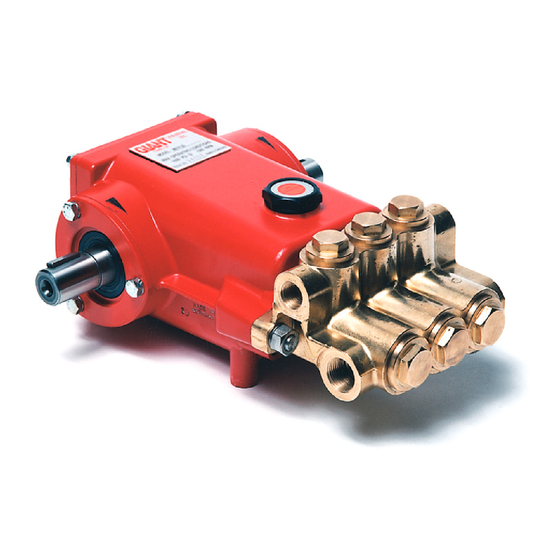
Model
SP100HT/SP200HT
Contents:
Installation Instructions:
Pump Specifications:
Exploded View :
Parts List/Kits:
Torque Specs/Pump Mounting
Selection Guide/
Preventative Maintenance:
Repair Instructions:
Dimensions:
Warranty Information:
Triplex Ceramic
Plunger Pump
Operating Instructions/
Repair and Service
Manual
page 2
page 3 & 6
page 4
page 5
page 7
pages 8 -11
back page
back page
Advertisement

Related Manuals for Giant SP200HT


Summary of Contents for Giant SP200HT
- Page 1 Triplex Ceramic Model Plunger Pump Operating Instructions/ Repair and Service Manual SP100HT/SP200HT Contents: Installation Instructions: page 2 Pump Specifications: page 3 & 6 Exploded View : page 4 Parts List/Kits: page 5 Torque Specs/Pump Mounting Selection Guide/ Preventative Maintenance: page 7...
-
Page 2: Installation Instructions
Check oil level prior to starting and ensure trouble-free wa- tion. ter supply. Oil: Use only 23.7 ounces (0.7 litres) of Giant Oil (p/n 01154) or ISO VG 220 GL4 (e.g. Aral Degol BG220) or These operating instructions supplement the general oper- SAE 90 GL4 gear oil. -
Page 3: Specifications
Specifications Model SP100HT U.S. (Metric) Volume @ 900 RPM ..........7.1 GPM/426 GPH ..(26.9 L/min/1613 L/hr) Volume @ 750 RPM ..........5.9 GPM/354 GPH ..(22.5 L/min/1340 L/hr) Discharge Pressure ..........870 PSI ..........(60 bar) Power Consumption ..........4.7 BHP ..........3.5 kW Plunger Diameter .......... - Page 4 SP100HT EXPLODED VIEW...
- Page 5 SP100HT/SP200HT PARTS LIST ITEM PART DESCRIPTIONS ITEM PART DESCRIPTIONS 07258 Copper Seal Washer 07294 Crankcase 05289 Flinger 06968 Oil Filler Cap with Gasket 07297 Cover, Crankcase 07318-0010 Radial Shaft Seal 07319 Seal Retainer 07298 O-Ring, Crankcase Cover 07320 Manifold 07299...
- Page 6 NPSHR (900 RPM) ..........20.3 ft. of head ......... 6.2 mWs Consult the factory for special requirements that must be met if the pump is to operate beyond one or more of the limits specified above. SP200HT HORSEPOWER REQUIREMENTS 200 PSI 400 PSI...
-
Page 7: Pump Mounting Selection Guide
SP100HT/SP200HT TORQUE SPECIFICATIONS Position Part# Description Torque Amount 07186 Oil Sight Glass 106 in.lbs. (12 Nm) 01010 Screw 221 in.-lbs. (25 Nm) 07109 Oil Drain Plug 29 ft.-lbs. (40 Nm) 07114 Inner Hexagon Screw 132 in.-lbs. (15 Nm) 07311 Inner Hexagon Screw 22 ft.-lbs. - Page 8 REPAIR INSTRUCTIONS - SP100HT/SP200HT PUMP 1. With a 22mm socket, remove 2. Check o-ring (44) for wear and replace as necessary. Remove the the three discharge (43) discharge spring retainer (34), valve spring (35), and valve plate and three inlet (41) manifold (36).
- Page 9 REPAIR INSTRUCTIONS - SP100HT/SP200HT PUMP 8. With a valve puller remove 9. Remove the spacer (39A), pressure spring (33), support ring (51), the valve seat (37) and o-ring sleeves (50), and pressure ring (30), from the manifold (29) and (38) replace if worn. If exces- check for wear.
- Page 10 REPAIR INSTRUCTIONS - SP100HT/SP200HT PUMP To replace plunger oil seals (26), proceed to “Gear End Disassembly” section below. Otherwise, continue as described below. Before replacing pump manifold (29), first rotate crankshaft (18) until two outside plungers (24A) extend evenly forward. Next lubricate...
- Page 11 See instructions above for re-installing fluid end onto the gear end. 32. Fill the pump crankcase (1) with 24 oz. (710 mL) of Giant Industries’ oil and check the oil level with the dip- stick (5). Proper level is center of two lines. Reinstall the pump into your system.
- Page 12 A Returned Goods Authorization (R.G.A.) number and completed warranty evaluation form is required prior to the return to Giant Industries of all products under war- ranty consideration. Call (419)-531-4600 or fax (419)-531-6836 to obtain an R.G.A. number.