Table of Contents
Advertisement
Quick Links
Advertisement
Table of Contents

Related Manuals for Headwall HYPERSPEC INSPECTOR

Summary of Contents for Headwall HYPERSPEC INSPECTOR
- Page 1 HYPERSPEC INSPECTOR ® YPER NSPECTOR Installation and Operation Guide...
- Page 2 Copyright © 2015, Headwall Photonics, Inc. All rights reserved. This document and all diagrams are the property of Headwall Photonics, Inc. and may not be reproduced, copied, or translated by any means without the written permission of Headwall Photonics, Inc.This document contains information which is Proprietary and Confidential.
-
Page 3: Table Of Contents
® HYPERSPEC INSPECTOR Table of Contents ® Hyperspec Inspector Components................3 ® Hyperspec Inspector Operation................7 SWIR Cable Connection ..................7 VNIR Cable Connection..................9 Hyperspec® Inspector Operation ..................10 Log Dock ......................11 Button Dock Controls: ..................11 Live Video ..........................11 Live Video Control Buttons: ..................... 12 Motion ............................ - Page 4 ® HYPERSPEC INSPECTOR THIS PAGE INTENTIONALLY LEFT BLANK...
-
Page 5: Hyperspec ® Inspector Components
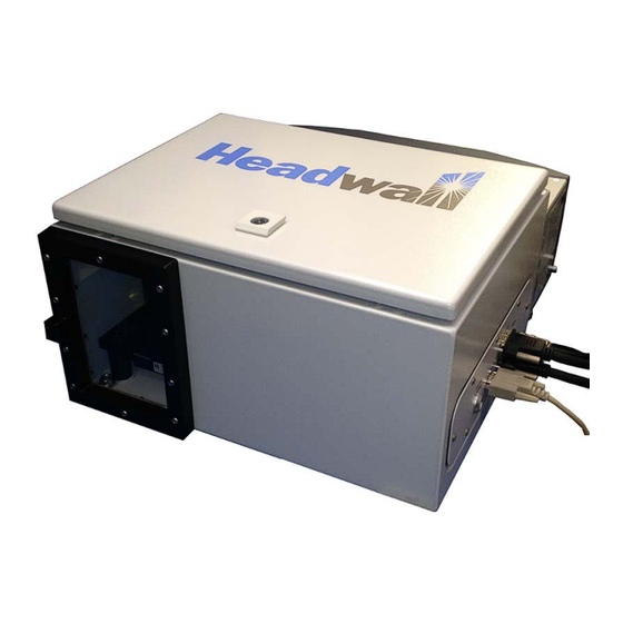
Processing Unit (cHDPU), Hyperspec III and SpectralView software and specific cables for system interconnection. The Hyperspec Inspector is available with either a NIR, EVNIR, VNIR or SWIR sensor and the respective lenses. The ® following components are the delivered Hyperspec Inspector systems. - Page 6 ® HYPERSPEC INSPECTOR ® Figure 1-2. Hyperspec Inspector Power Supply. Figure 1-3. Compact Hyperspectral Data Processing Unit (cHDPU). Figure 1-4. cHDPU Power Supply.
- Page 7 ® HYPERSPEC INSPECTOR Figure 1-5. Control Cables and Key. The system includes CameraLink cables to connect the Inspector to the cHDPU, and a motion control cable for moving the internal mirror. Depending upon the sensor type, one or two CameraLink cables may be included with the system. The key is for opening the Inspector housing, should adjustments or focusing become necessary.
- Page 8 ® HYPERSPEC INSPECTOR Figure 1-7. Internal View SWIR Inspector. Figure 1-8. SWIR Serial to USB Cable, Stage Serial Port.
-
Page 9: Hyperspec ® Inspector Operation
® HYPERSPEC INSPECTOR ® CHAPTER 2 HYPERSPEC INSPECTOR OPERATION ® The Hyperspec Inspector is a fixed position, hyperspectral scanning unit. While the system remains located in a single position, the internal mirror moves in an arc to scan a designated field of view. The mirror movement, system operation, capture parameters and data cube analysis is performed with the compact Hyperspectral Data Processing Unit, cHDPU. - Page 10 ® HYPERSPEC INSPECTOR Figure 2-2. SWIR Connected cHDPU. (1) Remove the Inspector from the storage case and set it onto a secure work surface. (2) Remove the cHDPU from its storage case and set it onto a secure work surface within a few feet of the Inspector. (3) Remove the cables and power supply from the cases.
-
Page 11: Vnir Cable Connection
® HYPERSPEC INSPECTOR (14) Connect the Inspector power cable to the power brick for the Inspector and the other end to the Power port of the Inspector. Secure the connector with the locking ring. (15) Connect the Inspector power brick to the appropriate power source. The Inspector will immediately power ON. (16) The system is ready to operate. - Page 12 ® HYPERSPEC INSPECTOR (1) Remove the Inspector from the storage case and set it onto a secure work surface. (2) Remove the cHDPU from its storage case and set it onto a secure work surface within a few feet of the Inspector. (3) Remove the cables and power supplies from the cases.
-
Page 13: Hyperspec® Inspector Operation
(2) Power on the Hyperspec® Inspector, if not already operating. (3) Allow the Inspector to complete the initialization steps. (4) If necessary, use the mouse and keyboard to log into the cHDPU. Default user name and password is headwall, lower case. -
Page 14: Button Dock Controls
Waterfall: Click the button to display the waterfall, real-time image of the video feed. This feature is an accurate facsimile of what would be captured during a scan. File Transfer: Click this button to transfer the data cube from the Headwall device to another, connected computer. -
Page 15: Live Video Control Buttons
Each click produces a single jpg. 2.4.2 Motion. The Headwall sensors can be mounted on a number of platforms to support hyperspectral scanning. Accurate viewing and analysis of the target requires that moving mirror pedestal speeds are identified and controlled. The motion control ®... - Page 16 ® HYPERSPEC INSPECTOR Figure 2-10. Inspector Mirror Motion Controls. ® The above figure is the motion control functionality within Hyperspec III. Note that the position and speed values are in degrees. The slide at the top is used to rotate the mirror to a specific location on an arc. The speed of travel is set with the Speed field.
-
Page 17: Light Level Calibration
To balance the light levels and collect the dark and white references in the Headwall sensor, use the following steps. (1) Position the Inspector so the window is aimed towards a bright light source or a reflective surface. - Page 18 ® HYPERSPEC INSPECTOR Figure 3-2. Auto-move, White Reference. Figure 3-3. Auto-move Dark Reference. (7) Close the Settings window. 3-16...
- Page 19 ® HYPERSPEC INSPECTOR (8) Click the Calibration button, shown circled in Figure 3-4. The Calibration window opens, labeled Uncorrected Video Histogram. The Histogram window is used to show the value of collected reference samples, and select the number of samples to collect using the pull-down to the left of the buttons.
- Page 20 (13) Close and restart the Hyperspec III application. (14) Verify the Dark and White reference files are in C:\\headwall\sensor1\calibration. The files are saved with a time stamp format. The most recent have no date/time stamp. The Inspector is now calibrated for hyperspectral scanning.
-
Page 21: Focus And Speed Adjustment
® HYPERSPEC INSPECTOR 3.2 FOCUS AND SPEED ADJUSTMENT ® With the Inspector and computer connected and powered ON. and Hyperspec III opened, perform the following steps. (1) Click the Live Video button, opening the live video feed from the sensor as seen in the following figure. Figure 3-7. -
Page 22: Fov Calculator
® HYPERSPEC INSPECTOR 3.2.0.1 FOV Calculator. ® The FOV calculator is used to set the Hyperspec III software to effectively capture images and integrate the sensor unit ® with the Hyperspec III application. In the above figure, click the FOV button in the red rectangle marked 2. The FOV Calculator, shown in the following figure, opens. - Page 23 ® HYPERSPEC INSPECTOR Figure 3-9. Motion Control. (b) Left-click and drag the slide to point the mirror to the desired object. (3) The view through the Live Video will appear similar to the one below. Note the minimal spectral plot, circled. Also, notice the vertical lines that can be used as a possible reference.
-
Page 24: Lens Focus
® HYPERSPEC INSPECTOR Figure 3-11. Live Video with Reflectance Image. (6) Notice the spectral plot improvement, circled, in the previous figure compared to Figure 3-11. At this point in the process it is important to compare the representative graphs in the spatial and spectral views of the display. - Page 25 ® HYPERSPEC INSPECTOR ® Figure 3-12. Hyperspec III with Improved Focus, Spatial and Spectral Plots. (3) Slowly rotate the mirror by small increments. (4) Set the pan speed to a value approximately 6 degrees per second. (5) Click the Waterfall button to open the waterfall view. (6) Left click and drag the slider approximately 25 degrees from the current setting and observe the waterfall view.
-
Page 26: Test Capture
® HYPERSPEC INSPECTOR The above example shows the waterfall as a blurred, blue hued image. The cause of the blurring is the speed of motion. When the unit stops moving, reduce the speed, left click the slider and move it to the original position. When the speed is set correctly the waterfall image will become clear. - Page 27 ® HYPERSPEC INSPECTOR ™ Figure 3-15. SpectralView Main Window. (10) Click the Open button and navigate to the folder where the data cube was transferred. The view will be similar to the following figure. Figure 3-16. Transfer File Directory. (11) Select the file that ends in .hdr, in the above figure it is raw_2000.hdr. (12) The data cube opens, as shown in the following image.
- Page 28 ® HYPERSPEC INSPECTOR Figure 3-17. Captured Data Cube. Note the similarity of the data capture to the focused waterfall image. ® At this point the computer and Hyperspec Inspector can be powered down. Or, if the target was the area to be scanned, detail scanning can commence.
Need help?
Do you have a question about the HYPERSPEC INSPECTOR and is the answer not in the manual?
Questions and answers