
Subscribe to Our Youtube Channel
Summary of Contents for Ross TC700MC
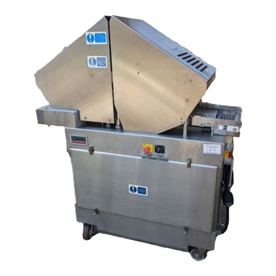
- Page 1 MODEL TC700MC TENDERIZER MADE IN USA Ross Industries, Inc. Midland, Virginia 22728 Phone: (540) 439-3271 (800) 336-6010 Fax: (540) 439-2740 MN700-MC0010...
- Page 2 MN700-MC0010...
-
Page 3: Introduction
The magnets provide just enough force to drive the blades through the toughest meat, but no more. When a ROSS blade hits anything tougher than meat, the magnetic force is overcome and the individual blade simply stops trying to penetrate –... -
Page 4: Safety First
Take a moment to note the areas on the machine where serious injury may occur if proper safety precautions are not adhered to. The ROSS Tenderizer has been carefully designed so that during normal use, the operator is never exposed to dangerous moving parts. -
Page 5: Daily Cleaning Procedure
6) Sanitize entire machine using only neutral pH sanitizers. 7) Rinse machine and Blade Assemblies with clean hot water. 8) Liberally spray the Magnetic Head Plates, Blades, Guide Uprights, Main Uprights and Seals with ROSS 601 Oil. 9) Replace Blade Assemblies in machine. CAUTION: NEVER USE CAUSTIC CLEANING SOLUTIONS ON THE ROSS TENDERIZER. -
Page 6: Table Of Contents
TABLE OF CONTENTS INTRODUCTION....................................i SAFETY FIRST! ....................................ii DAILY CLEANING PROCEDURE..............................iii SPECIFICATIONS ................................. 1-1 DESCRIPTION................................2-1 MECHANICAL ............................... 2-1 ELECTRICAL ................................. 2-1 INSTALLATION................................3-1 UNCRATING ................................3-1 INSTALLATION..............................3-1 ELECTRICAL REQUIREMENTS .......................... 3-2 POWER PHASING..............................3-3 INSTALLATION CHART............................3-4 SPARE PARTS ................................ -
Page 7: Specifications
1 SPECIFICATIONS R O S S P ERFO RM AN CE IN S TAI NL E SS WEIGHT 1000 pounds SIZE Length: 52”; Width: 24”, Height: 62” ELECTRICAL Voltage: The 700MC can be supplied to operate from any of the standard world wide three phase power system supplying from 208 to 575 volts. -
Page 8: Description
2 DESCRIPTION 2.1 MECHANICAL When the 700MC is turned on with the guard(s) in the closed position, the head assembly reciprocates. The conveyor advances when the blades are fully retracted at the top of each stroke. The meat to be tenderized is simply placed on the conveyor. The powered conveyor advances the product under the blades. - Page 9 disconnect switch (S1) to the line terminals L1, L2 and L3 of the motor starter (K1) and to terminals 3, 4, and 5 of the phase sensor. A single-phase connection from the incoming power is applied to the primary of the control transformer (T1) through fuses F2 and F3.
-
Page 10: Installation
3 INSTALLATION 3.1 UNCRATING The 700MC Tenderizer is shipped in an enclosed crate. The Tenderizer is supported by a wooden skid with wooden framing at the ends of the cabinet. The overall assembly is covered with clear polyethylene film and placed in a complete wooden crate. Prior to uncrating the Tenderizer, inspect the condition of the packing material;... -
Page 11: Electrical Requirements
move the Tenderizer by pushing or pulling on the guard assembly can result in misalignment of the guards. This can result in the safety switches being inoperative, which would prevent the Tenderizer from operating. 3.3 ELECTRICAL REQUIREMENTS The Model 700MC Tenderizer can be supplied to operate from any of the standard world wide three phase line voltages. -
Page 12: Power Phasing
NOTE - Always turn the main power switch OFF before connecting the machine to a power source. If the machine is plugged in with the main power switch ON and the head adjusting motor operating, the primary transformer fuses may blow. This is due to the high magnetizing in-rush current of the transformer added to the reflected starting load of the motor 3.4 POWER PHASING As with all three-phase motors, the phase sequence of the incoming power determines the direction of... -
Page 13: Installation Chart
3.5 INSTALLATION CHART MN700-MC0010... -
Page 14: Spare Parts
4 SPARE PARTS SPARES LIST VOLTAGE-DEPENDENT COMPONENTS IDENTIFIED WITH AN “*” VOLTAGE DESCRIPTION PART NO. FUSE, 1 AMP, (F5) 14140013 FUSE, 2A (F4) 14140023 200-219 *FUSE 2.5 AMP 600V, (F2, F3) 14140119 220-240 *FUSE 2 AMP 600V, (F2, F3) 14140195 380/415 *FUSE 1.5 AMP 600V, (F2,, F3) 14140194... - Page 15 SPARES LIST VOLTAGE-DEPENDENT COMPONENTS IDENTIFIED WITH AN “*” VOLTAGE DESCRIPTION PART NO. LIMIT SWITCH (S5, S6) 14120080 ROD END 13070013 BLADE, LONG ANGLE POINT 01019876 MN700-MC0010...
-
Page 16: Illustrations
5 ILLUSTRATIONS 5.1 GUARD/SAFETY SWITCH GUARD/SAFETY SWITCH MN700-MC0010... -
Page 17: Head Carrier Assembly
5.2 HEAD CARRIER ASSEMBLY MN700-MC0010... -
Page 18: Head Assembly
5.3 HEAD ASSEMBLY MN700-MC0010... -
Page 19: Conveyor Drive Assembly
5.4 CONVEYOR DRIVE ASSEMBLY MN700-MC0010... -
Page 20: Conveyor Assembly
5.5 CONVEYOR ASSEMBLY MN700-MC0010... -
Page 21: Motor/Reducer Assembly
5.6 MOTOR/REDUCER ASSEMBLY MN700-MC0010... -
Page 22: Cam Drive Assembly
5.7 CAM DRIVE ASSEMBLY MN700-MC0010... -
Page 23: Cam Assembly
5.8 CAM ASSEMBLY MN700-MC0010... -
Page 24: Return Spring/Cam Assembly
5.9 RETURN SPRING/CAM ASSEMBLY MN700-MC0010... -
Page 25: Toggle Clamp/Return Spring Assembly
5.10 TOGGLE CLAMP/RETURN SPRING ASSEMBLY 5-10 MN700-MC0010... -
Page 26: Main Frame/Rocker Bar Cam Follower
5.11 MAIN FRAME/ROCKER BAR CAM FOLLOWER 5-11 MN700-MC0010... -
Page 27: Operation
6 OPERATION 6.1 MACHINE OPERATION NOTE: The 700MC Tenderizer will not operate unless the safety guard is closed. Once the Tenderizer has been correctly installed and properly phased, the operation is extremely simple. A. Connect the line cord to a suitable source of power. B. -
Page 28: Cleaning And Blade Replacement
E. Sanitize blade assembly (maximum time in sanitizer 5 minutes). F. Blow dry blade assembly. 6. Oil blade assembly with Ross 601 white mineral oil (or equivalent) paying particular attention to the tops of the blades and magnetic head plates. - Page 29 12. Reinstall the Reset Plate and fasten with the original acorn nuts and washers. Tighten to a torque of 50 ft lbs. 13. After every cleaning, spray the blade assemblies, tops of the blades, main uprights and guide uprights with ROSS 601 white mineral oil (or equivalent). MN700-MC0010...
-
Page 30: Head Assembly Installation
6.3 HEAD ASSEMBLY INSTALLATION MN700-MC0010... -
Page 31: Maintenance
7.2 LUBRICATION DAILY OR AFTER EVERY CLEANING The magnetic head plates, tops of the blades, blade assemblies, main uprights and guide uprights should be sprayed with Ross 601 white mineral (or equivalent). EVERY 200 HOURS OR ONCE EVERY MONTH CRUSHING HAZARD TAG OUT, LOCK-OUT POWER. -
Page 32: Adjustments/Specific Repairs
To add oil, remove the plug on the top of the transmission and fill with USP extra-heavy white mineral oil (Ross Oil No. 15040014, or Exxon Primol 355, or equivalent) until oil level is even with the oil level plug. -
Page 33: Head Height Adjustment
7.3.2 HEAD HEIGHT ADJUSTMENT (blade-to-belt clearance) The blade to conveyor clearance has been set at the factory and should not change as a result of normal use. Although unlikely to occur, there are several reasons why this mechanism may need to be checked or adjusted: •... -
Page 34: Height Adjust Cam Mechanism
switch to the STD setting and observe blade to belt clearance when the head stops its’ travel. Re-adjust if necessary. The adjustable main upright(s) (p5-11, item 44) should never thread too far into the elevator nut(s) (p5-8, item 7). There should always be 2 to 4 threads showing in the STD position. CRUSHING HAZARD TAG OUT, LOCK-OUT POWER. -
Page 35: Toggle Ring Replacement
After the head height has been set correctly, the clearance between the tops of the blade assemblies, (p5-3, item 6), and the reset pad, (p5-2, item 2), should be checked. To do this, run the head assembly to the top of the stroke. Open the pivoting guard, (p5-1, item 1), and look for a space between the blade assembles tops and the bottom of the reset pad. - Page 36 I. Replace unlock cushion J. Make sure that the guide raisers (page 5-10, item 18), on the main uprights, are seated all the way down on the stabilizer bars and spacers (page 5-11, items 29,30) K. Make sure toggle assembly is centered on toggle rod. L.
-
Page 37: Troubleshooting
8 TROUBLESHOOTING TC700MC TROUBLESHOOTING CHART TENDERIZER TROUBLE CAUSE REMEDY No incoming power Check by measuring voltage at power socket, Machine plugged in, guards measure from phase to phase to phase – NOT to closed, main power switch pulled out, ground. - Page 38 TROUBLESHOOTING CHART TC700MC TENDERIZER TROUBLE CAUSE REMEDY Transformer, T1 faulty or connected wrong Check by measuring the voltage between (cont.) Machine plugged in, terminals X1 and X3 of the Transformer, this guards closed, main power switch should be 120 VAC.
- Page 39 TC700MC TROUBLESHOOTING CHART TENDERIZER TROUBLE CAUSE REMEDY Motor starter coil faulty Check by measuring the voltage across the two (cont.) Machine plugged in, (open) coil terminals of the starter after turning the guards closed, main power switch machine on and pressing the START switch.
- Page 40 TC700MC TROUBLESHOOTING CHART TENDERIZER TROUBLE CAUSE REMEDY Guide stop worn or broken Inspect and replace as required. Machine runs but makes a loud banging noise at bottom of each stroke. Guide frame may be hitting side of conveyor. Toggle not unlocking properly Check toggle and guide raiser assemblies.
- Page 41 TC700MC TENDERIZER TROUBLESHOOTING CHART TROUBLE CAUSE REMEDY Cam follower out of adjustment Remove side panel from the cabinet and Machine runs, but conveyor does remove the conveyor box cover panel. Rotate not advance, or advances irregularly. the conveyor drive shaft assembly until it is at the extreme end of its lateral movement (either way is OK).
- Page 42 TC700MC TENDERIZER TROUBLESHOOTING CHART TROUBLE CAUSE REMEDY Operator not removing bent blades promptly Train operator on the proper cleaning and Excessive blade bending. See maintenance of machine. Blade assemblies Section 6 must be removed for daily cleaning and any BENT OR DAMAGED BLADES REMOVED.
-
Page 43: Wiring/Schematic
9 WIRING/SCHEMATIC MN700-MC0010... - Page 44 MN700-MC0010...
Need help?
Do you have a question about the TC700MC and is the answer not in the manual?
Questions and answers