Table of Contents
Advertisement
Operating Instructions
Id.No.:
123 842
Type:
194 / 195 / 394 / 395
Version: 09
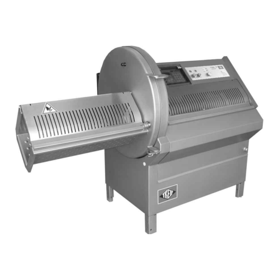
TREIF - PUMA-CE /E
TREIF - PUMA-CE /EB
TREIF - PUMA-CE /E HS
TREIF - PUMA-CE /EB HS
- english -
TREIF - Maschinenbau GmbH
LEBENSMITTELTECHNIK
D-57641 Oberlahr
Telefon: 0 26 85 . 944-0
Telefax: 0 26 85 . 10 25
E-Mail: info@treif.com
Händler:
Advertisement
Table of Contents

Summary of Contents for Treif PUMA-CE /E Series
- Page 1 123 842 Type: 194 / 195 / 394 / 395 Version: 09 TREIF - PUMA-CE /E TREIF - PUMA-CE /EB TREIF - PUMA-CE /E HS TREIF - PUMA-CE /EB HS - english - TREIF - Maschinenbau GmbH Händler: LEBENSMITTELTECHNIK D-57641 Oberlahr Telefon: 0 26 85 .
-
Page 2: Information On The Operating Instructions
Ask your operating and maintenance staff to confirm that they have read and understood these operating instructions. For this purpose use the record in chapter 20 If you need some more copies of these operating instructions, get in touch with your dealer or directly with TREIF Com- pany. Publisher... - Page 3 – Machine variants, dimensions, technical data What can be cut on the machine TREIF PUMA-CE ’electronic’ ? – Safety instructions Read by all means ! Necessary safety instructions for troublefree and safe operation. – These instructions describe how the machine is transported and how it is made operational.
-
Page 4: Table Of Contents
Information on the operating instructions Table of contents Information on the operating instructions ........Page 2 EC - declaration of conformity . - Page 5 Information on the operating instructions 13. Cutting instructions ............Page 59 13.1.
-
Page 6: Ec - Declaration Of Conformity
EC - declaration of conformity 2. EC - declaration of conformity Page 6 02/2005 123842-GB... -
Page 7: Dimensions And Technical Data
Dimensions and technical data 3. Dimensions and technical data 3.1. Machine specification Different versions of the TREIF PUMA-CE ’electronic’ are available. These variants differ in the lenght of the infeed chamber PUMA-CE 700 -E infeed length0700 mm PUMA-CE 1100 -E infeed length 1.100 mm... -
Page 8: Dimensions
Dimensions and technical data 3.2. Dimensions All specifications in mm 3.2.1 TREIF PUMA-CE ’electronic’ without conveyor Dimensions in brackets ( ) for PUMA-CE 1100 Space requirement Page 8 02/2005 123842-GB... - Page 9 Dimensions and technical data 3.2.2 TREIF PUMA-CE ’electronic’ with conveyor Dimensions in brackets ( ) for PUMA-CE 1100 Space requirement Page 9 02/2005 123842-GB...
-
Page 10: Technical Data
The thermal motor switch could switch the machine off for a short time. 3.4. Range of operation and intended application Use TREIF PUMA-CE ’electronic’ only to cut foodstuffs, such as meat, sausage, cheese or fish. The temperature of the product must not drop below -4° Celsius. -
Page 11: Centre Of Gravity Of The Machine
Dimensions and technical data 3.5. Centre of gravity of the machine TREIF PUMA-CE elektronic without conveyor TREIF PUMA-CE elektronic with conveyor Page 11 02/2005 123842-GB... -
Page 12: General Arrangement Of The Machine
General arrangement of the machine General arrangement of the machine 4 5 6 Cover of the removal chamber Door latch Knife box door with integrated removal chamber Control panel Loading door Additional control panel Feed cover Main switch (Emergency-shut down) Pneumatik-Wartungseinheit Page 12 02/2005 123842-GB... - Page 13 General arrangement of the machine Knife Counterblades only for machines with conveyor Conveyor Conveyor support, adjustable in height Control panel for conveyor Page 13 02/2005 123842-GB...
-
Page 14: Safety
! 5.1. On-the-job safety instructions 5.1.1 Intended use – The use of the machine TREIF PUMA-CE ’electronic’ might be dange- rous. For this reason the plant may only be operated by trained staff applying it according to the intended use. - Page 15 Safety 5.1.3 Qualification and duties of staff – The machine TREIF PUMA-CE ’electronic’ may only be operated, main- tained, and repaired by authorized, trained, and instructed staff. These persons have to receive special instructions on the potential hazards. – Every person who is involved in the erection, initial operation, handling, and maintenance of the machine has to read and understand the complete operating instructions, and especially the chapter on “safety...
- Page 16 – Spare parts or accessories supplied by, respectively expressedly appro- ved off by TREIF may be replaced or screwed to the machine only. This applies especially for contactors “K1M”, “K1S” and “K3" ! – Unauthorized rebuilding and modification of the machine which could impair the safety is prohibited.
-
Page 17: Warning Signs On The Machine
Safety 5.2. Warning signs on the machine Several warning signs have been attached to the machine. All of these signs have to be in place, and have to be legible. If required, they can be ordered. 1. Knife box: DANGER OF INJURY BY CUTTING ! 2. -
Page 18: Transport And Erection
Transport and erection 6. Transport and erection 6.1. Transport We recommend to have the machine erected and connected by the dealer only. It would be useful, if your own maintenance staff were present during erection and connection. Transport the machine as closely as possible to the site of erection, before the packing is removed. - Page 19 6.2: Erection If your machine is fitted with wheels: (optional extra) A set of wheels is available as an optional extra for the TREIF PUMA-CE ’electronic’. The wheels shown on the right in the drawing are castors.
-
Page 20: Electrical Installation
Transport and erection 6.3. Electrical installation The machine has to be installed and secured by a chartered electrician in compliance with the regulations applicable at the location of erection. Please note the electric circuit diagram in the catalogue of spare parts in the manual ! Please refer to the identification plate for the power of the back-up fuse to be provided by the customer. -
Page 21: Pneumatic Connection
Transport and erection 6.4. Pneumatic connection Pneumatic facility: - Operating pressure: 6 bar - Air consumption: max. 60 Ltr./min. (Refer to label on the machine) NOTE: The air supply must be free of oil and water ! Connection to the maintenance units takes place via a plug connector. 6.4.1 Adjustment/correction of operating pressure The operating pressure of the compressed air supply must constantly be adjusted to 6 bar. -
Page 22: Fitting Conveyor
Fitting conveyor 7. Fitting conveyor (only on machines with conveyor) Attention: DANGER OF TILTING ! When the conveyor is fitted the machine is top heavy when the knife box door is opened ! For this reason always dismount the conveyor when you wish to open the knife box door ! 7.1. -
Page 23: Removing / Fitting Conveyor Belt
Fitting conveyor 7.3. Removing / fitting conveyor belt (only for dismounted conveyor) Remove conveyor belt Dismount conveyor (cf. chapter 7.1). Rest the conveyor belt on the holding device of the friction-drum motor. Tilt the roller bearing as shown. Slant the conveyor belt and remove the belt to the side. -
Page 24: Trial Run
Trial run 8. Trial run Prior to the initial operation the maintenance staff of the machine has to carry out a trial run in order to check the functions of the machine. Furthermore, this trial run has to be carried out in the event of every new start-up, i.e. -
Page 25: Sense Of Rotation Test Of The Electric Motor
Trial run 8.1. Sense of rotation test of the electric motor Close knife box door. Remove all loose objects from the insertion shaft. Set main switch to » ON« The following display will appear: Please open the lid of the cutting chamber and close it again ! Please open the infeed device and close it again... -
Page 26: Performance Test Of The Safety Switches
! Note: Defective safety switches may only be replaced by the aftersales services staff of TREIF or a chartered electrician ! Carry out the performance test of the safety switches as follows: Set the main switch to »ON«. - Page 27 Trial run 8.2.2 Safety monitoring " extraction lid" Start up the machine again. Open the cover of the removal chamber by a maximum of 8 mm whilst the product feed holder is moving: The feeding action has to be interrupted immediately ! The display will read as follows: Emergency ! Pass-out chamber...
-
Page 28: Setting Up Operations
Setting up operations 9. Setting up operations 9.1. Product feed holder Two different cutting material holders are used with the TREIF PUMA-CE ’electronic’ 9.1.1 Manual cutting material retainer The cutting material holder can be adjusted to suit different cutting materials via transfer of the infeed plate. -
Page 29: Mount / Change Of Knife
TREIF. Loosen both hexagonal nuts (SW24) by means of the provided ring spanner. (refer to photo). -
Page 30: Accessory
Accessory 10. Accessory 10.1. Conveyor belt in the insertion shaft Set the main switch to position OFF, and remove the mains plug from the power outlet. Dismounting the holding appliance: Open filling cover to the limit stop Lift retainer away from the chamber wall slightly and pull back. Disassemble the conveyor belt Remove feed cover upwards. - Page 31 Accessory refer to chapter 10.1:Fit / replace conveyor belt in the feeding box Fitting the conveyor Open filling cover to the limit stop Remove feed cover upwards. Insert the rear conveyor belt (arrow) in the feeding box as shown. Insert the front conveyor belt (arrow) in the feeding box as shown. Tighten the star grips.
-
Page 32: Method Of Operation Of The Control
Method of operation of the control 11. Method of operation of the control The control of PUMA-CE “electronic” provides a multitude of functions and adjustment possibilities. We recommend that you carefully read the next two chapters in order to be able to take advantage of all possibilities of the machine. Tip: It is recommended to note the storage locations with the different products. -
Page 33: General Handli
11.4. Shortcut program selector keys The operator console of the TREIF PUMA-CE ’electronic’ has 12 shortcut program selector keys. You should file your most frequently used cutting programs in these program storage spaces. -
Page 34: Cutting Programs: Number And Type
11.5. Cutting programs: number and type 11.5.1 Number of memory locations: The electronic control of TREIF PUMA-CE “electronic” has a total of 32 memory locations, which can be occupied by various cutting programs. The program sites S1 to S20 are occupied with five sites each for the four modes of operation. -
Page 35: Minimum/Maximum Input
( ) behind the value adjusted. 11.7. Adjustment of mode of operation There are 4 possible operating modes when cutting with the TREIF PUMA-CE ’electronic’. The current operating mode is indicated by * in the bottom line of the display. -
Page 36: Program Parameters
Method of operation of the control 11.8. Program parameters Each cutting program contains a wealth of program parameters (depen- ding on the mode of operation selected). The adjustable limiting values for each program parameter are displayed in [] in the third line of the display (please also observe chapter 11.6) s3 ESCALOPES Cutting thickness 15 mm... - Page 37 Method of operation of the control – Number of empty cuts: This parameter renders the number of knife revolutions, during which the product is not fed forward. Empty cuts between 0 and 99 may be entered. This parameter is selectable in LS mode of operation only. –...
-
Page 38: Cutting Zones - Definition
Method of operation of the control 11.9. Cutting zones - definition When a single knife is used, the product can be divided up in up to ten different cutting zones (example: 3). The remaining centre piece between first cut [A] and the remaining piece [B] is divided up proportionately“ in zone lengths. -
Page 39: Storage Of Cutting Programs
Method of operation of the control 11.10. Storage of cutting programs It is not necessary to store immediately each individual change of a setting in MEMO/QUIT. Storage in MEMO/QUIT should be performed only when all the settings of the program have been correctly adjusted. Change of cutting program If you change to another cutting program without having stored the previous changes, the following display will appear:... -
Page 40: Entering / Modifying The Product Name
Method of operation of the control 11.11. Entering / modifying the product name A product name can be entered or modified with the machine at a standstill only. Task: The product name of "piece of roast" is to be entered in a free program storage location. -
Page 41: Operating Mode Single Knife (Single)
Method of operation of the control 11.12. Operating mode single knife (single) Selecting the cutting program (cf. chapter 11.4:Program softkeys) Set the main switch to »ON«. After display of the program version, the control system automatically performs a ’reference run’, in order to determine required length parame- ters. -
Page 42: Operating Mode Double Knife (Single)
Method of operation of the control 11.13. Operating mode double knife (single) Selecting the cutting program (cf. chapter 11.4:Program softkeys) Set the main switch to »ON«. After display of the program version, the control system automatically performs a ’reference run’, in order to determine required length parame- ters. -
Page 43: Operating Mode Single Knife 'Rs' Cutting Within A Cutting Range
Method of operation of the control 11.14. Operating mode single knife ’RS’ Cutting within a cutting range (Definition "CUTTING RANGE", refer to section 11.9.) This section describes the procedure applied, if a strand of cutting material between a defined first cut [A] and a residual piece [B] is to be cut into equally sized slices. - Page 44 Method of operation of the control Refer to chapter 11.14.: Operating mode single knife ’RS’ Cutting within a cutting range Alter cutting parameters Alteration of set values is only possible prior to the first cut! The different cutting parameters can be invoked in succession according to the following scheme by means of the program-content key "ARROW UP".
- Page 45 Method of operation of the control Refer to chapter 11.14.: Operating mode single knife ’RS’ Cutting within a cutting range s2 beef olive meat final piece 20 mm (0-250) s2 beef olive meat cutting thickn. tol. 10 % (0-20) s2 beef olive meat cutting regions 1 piece (1-10)
-
Page 46: Operating Mode Single Knife 'Rs' Cutting Within Several Cutting Ranges
Method of operation of the control 11.15. Operating mode single knife ’RS’ Cutting within several cutting ranges (Definition "CUTTING RANGE", refer to section 11.9.) This section describes the procedure applied, if a strand of cutting material between a defined first cut [A] and a residual piece [B] is to be cut in different cutting ranges (example = 3) and different slice thick- nesses. - Page 47 Method of operation of the control Refer to chapter 11.15.: Operating mode single knife ’RS’ Cutting within several cutting ranges Alter cutting parameters Alteration of set values is only possible prior to the first cut! The different cutting parameters can be invoked in succession according to the following scheme by means of the program-content key "ARROW UP/ DOWN".
- Page 48 Method of operation of the control Refer to chapter 11.15.: Operating mode single knife ’RS’ Cutting within several cutting ranges s4 cutlets CUTTING THICKNESS 30 mm (0,5-250) s4 cutlets Length range 2/3 50 % (0-70) s4 cutlets CUTTING THICKNESS 15 mm (0,5-250) s4 cutlets Length range 3/3...
- Page 49 Method of operation of the control Refer to chapter 11.15.: Operating mode single knife ’RS’ Cutting within several cutting ranges s4 cutlets first cut 30 mm (0-250) s4 cutlets final piece 20 mm (0-250) s2 beef olive meat cutting thickn. tol. 10 % (0-20) s2 beef olive meat...
-
Page 50: Operating Mode Single Knife Ls Cutting With Empty Cuts
Method of operation of the control 11.16. Operating mode single knife LS Cutting with empty cuts This section describes the possibility of cutting up a previously defined number of slices to a group of slices by including empty cuts and depositing them at intervals. - Page 51 Method of operation of the control Refer to chapter 11.16.: Operating mode single knife LS Cutting with empty cuts s16 escalopes first cut 40 mm (0-250) s16 escalopes final piece 15 mm (0-250) s16 escalopes number of empty cuts 10 piece (0-99) s16 escalopes number of slices/stack...
- Page 52 Method of operation of the control Refer to chapter 11.16.: Operating mode single knife LS Cutting with empty cuts s16 escalopes return travel 5 mm (0-15) s16 escalopes cutting thickn. tol. 10 % (0-20) s16 escalopes mode of optimation per cent (quantity) To start cutting program, refer to section 12.
-
Page 53: Conveyor Control
Method of operation of the control 11.17. Conveyor control (only for machines with conveyor) Conveyor speed ...can be adjusted both prior to and during the cutting operation by means of speed controller . The adjustment is independent of the selected cutting program. -
Page 54: Cutting Products
Cutting products 12. Cutting products 12.1. Before you start . . . Before putting the machine into operation, check the function of the safety buttons every day ! (chapter 8.2) If one of the safety covers is opened or removed during a cutting process, the machine is switched off automatically, and the knife comes to a standstill instantaneously! By this action, the knife may come to a standstill in the chamber. -
Page 55: Running The Cutting Program
Cutting products 12.4. Running the cutting program Place the product as described in chapter 12.3.1 Depending on the position of the ’LID START’ 3 switch:: – LID START OFF (lamp off): Press START button. The machine starts running! – LID START ON (lamp on): The machine starts upon closure of the replenishing cap. -
Page 56: The Single-Cut Function
Cutting products 12.6. The single-cut function The single-cut function has mainly two purposes: – cutting the product individually with different cutting thicknesses – interrupting a cutting process to cut, for example, a roast piece out of a cutlet section. Cutting a product piece individually: Open the infeed cover Insert cutting material and attach to the cutting material retainer. -
Page 57: Return Travel Limitation Of The Product Feed Holder
Cutting products 12.7. Return travel limitation of the product feed holder Purpose: If a particular cutting programme is used always to cut short products (e.g. escalope), the return travel of the product feed holder in the infeed chamber can be limited. In this way, empty travels of the product feed holder can be avoided. -
Page 58: Brake Release" Push-Button
Cutting products 12.8. BRAKE RELEASE" push-button The key "loosen brake" is for fault clearance, if for instance the knife jams in the knife slot as a result of bone splinters, and for twisting the knife into a freely accessible position while exchanging the knife. If the knife jams in the shaft: Open the knife box door. -
Page 59: Cutting Instructions
Cutting instructions 13. Cutting instructions 13.1. Types of knife available A wide selection of knives is available for the PUMA-CE. As a standard feature the machine is equipped with a “single knife” and a “double sickle-shaped knife”, if nothing to the contrary has been agreed upon when the machine is ordered. -
Page 60: Place The Product Properly
Cutting instructions 13.2. Place the product properly ! Cutlets with rib bones Belly If possible, place the rib bones Place the belly as shown in the along the front wall of the infeed drawing. The rind must always chamber. be underneath. Other notes: –... -
Page 61: Cutting With Or Without Counter-Blade
Cutting instructions 13.3. Cutting with or without counter-blade (For machines with a conveyor belt only) It is sensible to cut without a counter-blade when cutting thin slices (< 5 mm). This way the cut off slices are fanned out more precisely onto the conveyor belt. -
Page 62: Cleaning
After every cleaning process, inspect the knife shaft seal (arrowed) for visible damage. If it is damaged, have it replaced by the TREIF service engineer imme- diately ! For machines with a conveyor belt only ! -
Page 63: Preparatory Work For Cleaning
Cleaning 14.1. Preparatory work for cleaning For machines with a conveyor belt only Disassemble the conveyor belt (cf. chapter 7.1.) No water may penetrate into the plug housing when cleaning the conveyor belt ! Remove conveyor belt (cf. chapter 7.3) Dismounting the holding appliance: Lift retainer away from the chamber wall slightly and pull back. - Page 64 Cleaning refer to chapter 14.1: Preparatory work for cleaning Removing the knife: Always wear the personal protective gear prescribed in the chapter " safety" when working in the open cutting range and when cleaning the knife! ! Loosen both hexagonal nuts by means of the provided ring spanner. Hold the knife with one hand and unscrew both nuts.
-
Page 65: Instructions For Cleaning
Cleaning 14.2. Instructions for cleaning In order to avoid damage to the machine and to guarantee a hygienic cleaning of the machine, cleaning has to be effected according to the cleaning, and disinfection plan listed below. The data in the cleaning plan refer to single-shift-operation ! ! Solely the specified and approved cleaning agents and disin- fectants may be used, in order to avoid damage to the machine. -
Page 66: Cleaning And Disinfection Plan
Cleaning 14.3. Cleaning and disinfection plan Pre-Cleaning (Start after finishing production) Working steps Detergent Process Appliances Notes Coarse cleaning, – – – manual, plastic spatula, – – – (removal of mechanical plastic scraper product rests) Dismantling of – – – –... - Page 67 Cleaning Disinfection (after completion of all cleaning measures to be carried out within the room) Working steps Detergent Process Appliances Notes Disinfection Ecolab: spray low-pressure Spray small parts small parts P3-alcodes cleaning device, from top to bottom. atomiser pistol, dosage device Disinfection Ecolab: spray, lather,...
-
Page 68: Remounting After Cleaning
Cleaning 14.4. Remounting after cleaning Assembly of product feed holder: (With manual cutting material holders only) Insert spindle as shown in the drawing. Install locking lever turn spindle downwards. Fit clamping lever (observe correct fitting position). Push shaft into the frame of the product feed holder to a distance of a few centimetres. - Page 69 Cleaning ref. to chapter 14.4: Remounting after cleaning Mounting of knife: Place the knife on the knife shaft (wrong fitting is not possible due to the different diameters of the mounting holes). Place retaining disc (observe fitting position !). Tighten hexagon nuts Always wear your personal protective clothes and equipment described in the chapter “...
-
Page 70: Maintenance
Maintenance 15. Maintenance The function of the safety switches has to be verified after all maintenance and repair work (chapter 8.2) Carry out an operational check after every maintenance work. Being the buyer/operator, have the check-up work confirmed. In this way the adherence to the check-up work for safety and warranty reasons can be verified easier. -
Page 71: Knife Sharpening
NOTE It is not possible to regrind serrated knives on site as special sharpening equipment is required for the purpose. Please get in touch with your dealer or directly with TREIF ! Please send your blunt cut-off knife to the following address with a note reading “for regrinding”:... -
Page 72: Greasing Of The Feed Guide Part
Maintenance 15.3. Greasing of the feed guide part The friction bearing of the feed guide part has to be greased every 40 operating hours. For this purpose use the grease gun supplied along with the machine. IMPORTANT: Move product feed holder into its furthermost, right-hand end position. -
Page 73: Adjustment Of The Counterblade
Maintenance 15.4. Adjustment of the counterblade ATTENTION: the counterblade is fragile. Do not drop it ! If a new counterblade is mounted for the first time, the gap to the non-cutting knife edge has to be set anew. Please proceed as follows: (knife has to be mounted previously) Set the main switch to “ON”. - Page 74 Maintenance ref. to chapter 15.4. Adjustment of the counterblade Undo collar nuts and disassemble the counterblade. Loosen both lock nuts on the back side of the counter-blade Preset hexagon head cap screws to a height of approx. 49 mm (Refer to measurement "X" drawing) Do not tighten lock nuts Fit the counterblade correctly, and use collar nuts to screw down.
- Page 75 Maintenance ref. to chapter 15.4. Adjustment of the counterblade Readjust distance of the counter-blade Loosen both union nuts half a turn. Loosen hexagon head screw with washer and unscrew. Readjust the distance of the counter-blade via hexagon head screws . For this purpose, insert a screwdriver into the front end of the threaded hole (M6x8) and adjust both hexagon head screws to the desired degree.
-
Page 76: Height Adjustment Of The Counter-Blade
Maintenance 15.5. Height adjustment of the counter-blade The height of the counter-blade can be adjusted to suit the respective cutting material, in order to attain a better cutting result Set the main switch to “ON”. Dismount conveyor when fitted. Open the knife box door. Press the ’Brake release’... -
Page 77: Retensioning The Conveyor Belt
Maintenance 15.6. Retensioning the conveyor belt (only for machines with conveyor) If the conveyor belt moves lopsided or slips it must be retensioned as follows: Let the machine run in slow conveyor speed. For retensioning evenly turn the clamping screws (arrows) clockwise until the conveyor does not slip any more. -
Page 78: Fault Finding
Fault finding 16. Fault finding Failure Reason Remedy No LCD display Main switch not turned on Turn on main switch Supply line has not been connected Check supply line properly Fuse in power feed cable defective Replace Display shows: Knife box door not closed Close Emergency off –... - Page 79 Fault finding Failure Reason Remedy Cuts are not cut through pro- Knife tip is too short due to frequent Replace knife perly regrinding Knife sticks in Bone fragments in product Release brake and remedy the channel failure cf. chapter 12.8 Poor cutting results Knife is blunt Regrind or replace knife...
-
Page 80: Repair Instructions
Repair instructions 17. Repair instructions The work described below may only be carried out by the service department or especially trained staff. Note:When carrying out any work on the electrical systems, always observe the information in the relevant circuit diagram. Do not hesitate to telephone our customer service department with any questions you may have. - Page 81 Repair instructions Failure Reason Remedy Knife motor does not run Contactor K1M or K4 is defective Replace May be replaced by same make / type only ! Brake of knife motor is defective Replace or repair CPU N1 defective Replace ’Brake release’...
-
Page 82: Service Menu
Modifications of the adjusted values may cause wrong functions of the machine ! Purpose: TREIF PUMA-CE ’electronic’ has been provided with a service menu, in which various parameters have to be determined and then adjusted in dependence of some “hardware” components (eg. light barrier). -
Page 83: General Operation
Service Menu 18.2. General operation Select the requested menu item. Press the Service key for acknowledgement. Depending on the menu item selected, the input of the service code is requested. Use the program function keys to enter P2, P5, P4, and P6 after each other. -
Page 84: Calibration Routine
Service Menu 18.4. Calibration routine Press the Service key to access the service menu. Select the CALIBRATION ROUTINE parameter. Use the program function keys to enter P2, P5, P4, and P6 user code after each other. In the process, press the Shift key and keep it pressed. -
Page 85: Stockkeeping Of Spare Parts
TREIF PUMA-CE ’electro- nic’, and thus might impair the active and/or passive safety. Damage which occurs due to the use of non-original TREIF spare parts and accessories shall be excluded from any liability and guarantee on the part of TREIF Maschinenbau GmbH. -
Page 86: Records
Records 20. Records 20.1. Instruction record Ask your operating and maintenance staff to confirm in the following list that they have read and understood these operating instructions. These operating instructions have been read and understood. Date Name Signature 20.2. Maintenance record Ask your maintenance staff to confirm in the following list the mainten- ance work and performance tests carried out. -
Page 87: Your Cutting Programs
Your cutting programs 21. Your cutting programs Product-name Cutting Length / First cut Remaining Number thickness Number of piece of empty cuts slices Page 87 02/2005 123842-GB... - Page 88 Your cutting programs Slices/ Return 1 / 2 Tolerance Cutting Type of Mode of packet: travel Slice in cutting zone optimisation operation thickness Page 88 02/2005 123842-GB...
Need help?
Do you have a question about the PUMA-CE /E Series and is the answer not in the manual?
Questions and answers
What is code 550
What is code 550 on a puma 700eb