
Related Manuals for Alicat MC Series


Summary of Contents for Alicat MC Series
- Page 1 Operating Manual WHISPER MC-Series MCS-Series MCV-Series MCR-Series Precision Gas Mass Flow Controllers The Fastest Flow Controller Company in the World!
- Page 2 Service Request Form at alicat.com/service. This Alicat device comes with a NIST traceable calibration certificate. This Alicat flow controller conforms to the European Union’s Restriction of Use of Hazardous Substances in...
- Page 3 26. Backlit display with adjustable contrast • is easy to read in direct sunlight. In dimly lit areas, press the Alicat logo to turn on the backlight, page 7. Change your STP • to match any standard temperature and pressure reference, page 35.
-
Page 4: Table Of Contents
Table of Contents Quick-Start Guide ________________________________________6 Getting Started __________________________________________7 Getting to Know Your Alicat ..................7 Connectors and Buttons ..................7 The Flow Controller Display .................8 Status Messages ....................8 Mounting ........................9 Plumbing ........................9 Filters ..........................9 Connecting Your Gas Flow Controller ................10 MCV Controller Operating Notes ................11 MCD Dual Valve Mass Flow Controller Operating Notes ........12... - Page 5 Gas Properties Data ______________________________________ 49 Numerical List of Gases ____________________________________ 57 Device Units ___________________________________________ 60 Accessories ____________________________________________ 62 Accessories .........................63 Specification Sheets ______________________________________ 64 Optional Pinouts ________________________________________ 94 Additional Information for Alicat CSA and ATEX Approved Devices _______ 98 Limited Lifetime Warranty ________________________________ 101...
-
Page 6: Quick-Start Guide
Operation: Pressure Control with Flow Monitoring • Switch the closed loop control to pressure. Select MENU > CONTROL > ADV CONTROL > LOOP SETUP > LOOP VAR, and then choose Absolute Pressure. Your Alicat will now control absolute pressure while monitoring flow rate. -
Page 7: Getting Started
Connectors and Buttons The drawings below represent the default configuration of a standard Alicat mass flow controller (MC series) with an upstream valve. Your flow controller's appearance and connections may differ, especially if it has been ordered with a large Rolamite valve or a downstream valve. -
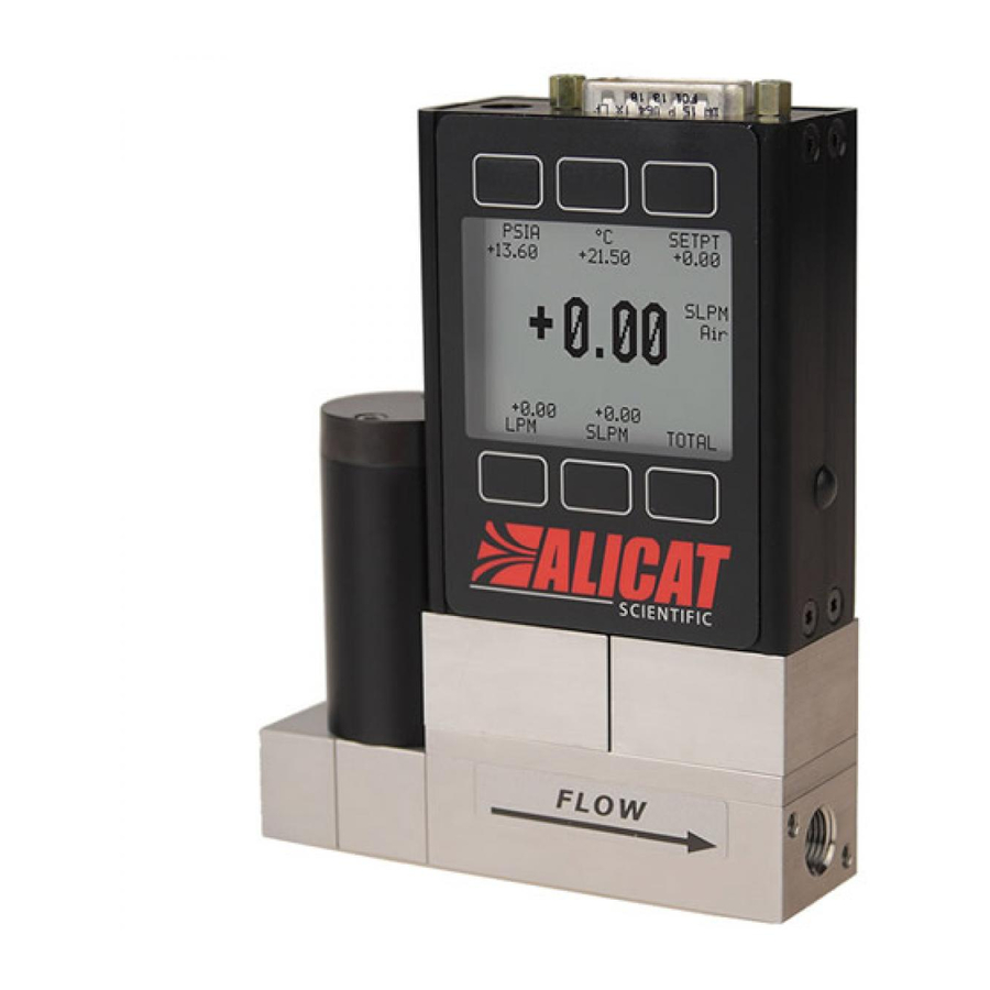
Page 8: The Flow Controller Display
The figure below identifies the various features of the flow controller display. Press the large button with the Alicat logo to toggle the backlight on and off. For more details, see the Menu Map on page 18 and the menu-by-menu descriptions that follow it. -
Page 9: Mounting
Mounting No straight runs of pipe are required upstream or downstream of the flow controller. Most Alicat flow controllers can be mounted in any position, including upside-down. (MCS/MCRS series flow controllers use media-isolated sensors that must be tared after changing orientation.) -
Page 10: Connecting Your Gas Flow Controller
Getting Started Connecting Your Gas Flow Controller Your Alicat flow controller can measure and control flow generated by positive pressure and/or suction. Connect the controller so that the flow travels in the same direction as the flow arrow, usually from left to right as you look at the front of the device. -
Page 11: Mcv Controller Operating Notes
Getting Started MCV Controller Operating Notes Alicat’s MCV mass flow controller is equipped with an integrated Swagelok® positive shutoff valve. The normally closed valve is actuated by a gas (typically air) and opens when supplied with 60-120 psig of pressure. The shut-off valve closes again when this pressure is removed. -
Page 12: Mcd Dual Valve Mass Flow Controller Operating Notes
• Control absolute pressure or back-pressure in a flowing process. • Control absolute pressure in a closed volume with automatic venting. Application examples are shown below and on the following page. Please contact Alicat if you have any questions regarding MCD use. Outlet Valve Process Connection... - Page 13 Getting Started Bidirectional Mass or Volumetric Flow Control Vacuum Source or Vent FLOW Gas Source Process FLOW Flowing Absolute Pressure Control Vacuum Source or Vent Back-Pressure Control Gas Source Process Positive Pressure Control Dead-Ended Absolute Pressure Control Vacuum Source or Vent FLOW Closed Process Gas Source...
-
Page 14: Power And Signal Connections
It is common to mistake Pin 2 (labeled 5.12 Vdc Output) as the standard 0-5 Vdc analog output signal. Pin 2 is normally a constant 5.12 Vdc that reflects the system bus voltage. For 6-pin locking industrial connector, DB9 and DB15 pinouts, see page 92 to page 95 or visit alicat.com/pinout. -
Page 15: Rs-232 / Rs-485 Digital Input / Output Signal
Getting Started RS-232 / RS-485 Digital Input / Output Signal To use the RS-232 or RS-485 digital signal, connect the RS-232 / RS-485 Output Signal (Pin 5), the RS-232 / RS-485 Input Signal (Pin 3) and Ground (Pin 8) to your serial port as shown below. -
Page 16: Analog Signals
Analog Signals Primary Analog Output Signal Most Alicat instruments include a primary analog output signal, which is linear over its entire range. For both standard 0-5 Vdc and optional 0-10 Vdc output signals, a zero flow condition is usually in the range of 0.010 Vdc. Zero flow for the optional 1-5 Vdc and 4-20 mA output signals is 1 Vdc and 4 mA, respectively. -
Page 17: Option: Color Tft Display
» YELLOW: Menu items that are ready to be selected appear in yellow. This color replaces the symbol (>) in selections on monochrome display. Press the Alicat logo button to turn off the color display backlight. The flow meter remains in operation while the backlight is off. -
Page 18: Navigating And Customizing Your Flow Controller
Navigating and Customizing Your Flow Controller Flow Controller Menu Map Start Here Main Display TOTAL/ SETPT SLPM PSIA SETPT +15.44 +13.60 +24.38 +15.44 TIMER +15.44 M AVG +15.44 SL +15.44 SLPM +45.29 Optional Flow 2:56 h:m:s Mass Flow Totalizer +16.67 +15.44 TOTAL/ +14.71... -
Page 19: Collecting Live Flow Data
Navigating and Customizing Your Flow Controller Collecting Live Flow Data The Main Display has three primary functions: • Collecting live temperature, pressure and flow data (see below) • Changing engineering units for temperature, pressure and flow (page 20) • Changing the flow or pressure control setpoint (page 26) This screen displays live data for all flow parameters simultaneously. -
Page 20: Choosing Engineering Units
Navigating and Customizing Your Flow Controller Choosing Engineering Units Press the button above or below any of the four flow parameters twice to enter its unit selection DOWN Show abs pressure menu. You can change units in two ways: > Show gauge pressure Show baro pressure Button engineering units alter the display only,... -
Page 21: Option: Collecting Totalized Flow Data And Batch Dispensing
Navigating and Customizing Your Flow Controller Option: Collecting Totalized Flow Data and Batch Dispensing Your flow controller may have an optional flow totalizer, which enables batch dispensing. The totalizer displays the total amount of mass or volume that has flowed through the instrument since its last reset, like a gasoline pump. Access the totalizer screen by pressing TOTAL/MENU on the Main Display. -
Page 22: Dispensing Gas In Batches
Navigating and Customizing Your Flow Controller Dispensing Gas in Batches Batch dispensing allows you to choose a desired total quantity to flow, after which the valve closes. You can repeat batches with a single button press. Totalizer - Batch On (Optional) SETPT Displays the current setpoint. - Page 23 Navigating and Customizing Your Flow Controller Dispensing Gas in Batches (continued) The Batch Size can be changed while a batch is in progress. If the new Batch Size is larger than the current totalized flow, then flow continues until the new value is reached.
-
Page 24: Menu
Navigating and Customizing Your Flow Controller Menu You can enter the menu system by pressing the MENU button from the Main Display. Menu ABOUT Enters the About Menu (page 29). TARES Enter the Tares Menu CONTROL ABOUT TARES TARE TARE AUTO FLOW PRESS... -
Page 25: Control Menus
Navigating and Customizing Your Flow Controller Control Menus The Control and Advanced Control menus allow you to command new setpoints, change the setpoint control loop and adjust PID settings, among other options. Menu | Control SETPT Displays the current setpoint. Press to command a new setpoint or clear the existing one. -
Page 26: Commanding A New Setpoint
Navigating and Customizing Your Flow Controller Commanding a new setpoint Press the SETPT button from either the Main Display or the Control Menu (MENU > CONTROL) to choose a new setpoint. The setpoint selection screen indicates the maximum allowable setpoint (e.g., SLPM 20.00 Max). To cancel a setpoint, press CLEAR. -
Page 27: Adjusting The Pid Controller
This is equivalent to the I variable in common PDF controllers. Note: The D and P variables in Alicat's PD/PDF control algorithm are more typically referred to as P and I, respectively, in PDF controllers. - Page 28 I for the first time, try gain settings of P=200, I=200 and D=20 as a starting point. Valve tuning can be complex. Please give us a call, and we'll be happy to guide you through the process. Or, visit alicat.com/pid for more detailed instructions.
-
Page 29: About
We hope you don't run into trouble using your flow controller, but if you do, the ABOUT menu contains information that can make the troubleshooting process easier. Select MFG INFO to look up Alicat's phone number and web address. DEVICE INFO shows you the serial number and firmware version (SW:) for your specific device. -
Page 30: Basic Configuration Menu
Navigating and Customizing Your Flow Controller Basic Configuration Menu The Basic Configuration Menu contains options for choosing the gas calibration, device engineering units and STP/NTP mass flow references. Menu | Basic Configuration DEVICE UNITS Changes device engineering units for any parameter: GAS Enters Gas Select and Mass Flow - Volumetric Flow - COMPOSER menus (page 31). -
Page 31: Gas Select
Navigating and Customizing Your Flow Controller Gas Select™ In most cases, your flow controller was physically calibrated on air at Alicat's factory. Gas Select™ allows you to reconfigure the flow controller to flow a different gas without sending it back to Alicat for a physical recalibration. -
Page 32: Gas Select™ Gas List
Navigating and Customizing Your Flow Controller Gas Select™ Gas List Your Alicat is preloaded with gas properties data for the following gases. See page 49 for gas properties data (viscosity, density and compressibility). Pure Non-Corrosive Gases Pure Corrosive Gases (*S-series only) •... -
Page 33: Using Composer™ To Personalize Mixed Gas Compositions
To remain accurate, your flow controller needs to know the viscosity of the gas you are flowing through it. The more closely you can define your actual gas composition, the more accurate your flow readings will be. Alicat's COMPOSER is an included feature of Gas Select that lets you define new mixed gas compositions to reconfigure your flow controller on the fly. -
Page 34: Adding A New Mixed Gas Composition To Composer
Navigating and Customizing Your Flow Controller Adding a new mixed gas composition to COMPOSER Generate and store a new COMPOSER mix in 3 easy steps. DOWN EDIT % DOWN NEXT LETTER 71.35% CH4 Methane COMPOSER Mix name: 3.00% C2H6 Ethane Name 1.00% C3H8 Propane... -
Page 35: Defining Stp/Ntp Reference Values
Using the STP/NTP menu, you can independently change the temperature or pressure references for STP and NTP. Your flow meter ships with Alicat default STP of 25°C and 1 atm (which affects flow units beginning with "S"), and an NTP of 0°C and 1 atm (which affects flow units beginning with "N"). -
Page 36: Advanced Setup
Navigating and Customizing Your Flow Controller Advanced Setup The Advanced Setup Menu lets you configure the display, deadband, averaging (for flow and pressure) and serial communications. Menu | Advanced Setup SENSOR SETUP Enters the Sensor COMM SETUP Enters the Communications DISP SETUP Enters the Display Setup Menu (page 37). -
Page 37: Sensor Setup
Navigating and Customizing Your Flow Controller Sensor Setup The Sensor Setup Menu contains advanced settings that govern how the flow and pressure sensors report their data. Advanced Setup | Sensor Setup DISPLAY AS ZERO Defines the deadband threshold under which flow values are displayed as 0. -
Page 38: Configuring Your Flow Controller For Serial Communications
The unit ID is the identifier that a computer uses to distinguish your flow controller from other Alicat devices when it is connected to a network. Using the unit ID letters A-Z, you can connect up to 26 devices to a computer at the same time via a single COM port. -
Page 39: Serial Communications
• If you have used a USB cable to connect your device to your computer, the computer in most cases will recognize your Alicat as a virtual COM port. If it does not, download the appropriate USB device driver at alicat.com/drivers and note the COM port number as found in Windows Device Manager. -
Page 40: Serial Streaming Vs Polling
Serial Communications Serial Streaming vs Polling Note: In what follows, <CR> indicates an ASCII carriage return (decimal 13, hexadecimal D). Serial commands are not case-sensitive. Polling Mode Your flow controller was shipped to you in polling mode with a unit ID of A, unless requested otherwise. -
Page 41: Taring Serially
Serial Communications Taring Serially Before collecting flow data, be sure to tare your flow controller. This can be accomplished serially through two separate commands. Taring flow sets the zero flow reading and must be done when no flow is passing through the flow controller: Tare flow: [unit ID]v<CR>... -
Page 42: Commanding A New Setpoint Serially
Serial Communications Commanding a New Setpoint Serially Before attempting to send setpoints to your mass flow controller serially, confirm that its setpoint source is set to Serial/Front Panel by selecting MENU > CONTROL > ADV CONTROL > SETPT SOURCE. There are two ways to command a new setpoint over a serial connection, as described below. -
Page 43: Quick Serial Command Guide
Delete a COMPOSER mix: agd [Mix Number]<CR> Query live data info: a??d*<CR> Query manufacturer info: a??m*<CR> Query firmware version: a??m9<CR> Lock the front display: al<CR> Unlock the front display: au<CR> If you have need of more advanced serial communication commands, please contact Alicat. -
Page 44: Using Gas Select And Composer Serially
Serial Communications Using Gas Select and COMPOSER Serially To reconfigure your flow controller to flow a different gas, look up its Gas Number (see "Numerical List of Gases" on page 57). Then type: Choose a gas: [unit ID]g[Gas Number]<CR> Example1: ag8<CR>... -
Page 45: Troubleshooting Your Flow Controller
Troubleshooting Your Flow Controller If you run into any trouble with your Alicat's installation or operation, please get in touch with us by phone, chat or email. You'll also find help on our website alicat.com and in the pages that follow. - Page 46 Issue: Can I put the Alicat on top of a vibrating device? Will it be accurate? Action: Yes, and yes! The flow controller is internally compensated for any changes in orientation, including rapid vibrations. Noise will increase if the flow meter/controller is vibrating.
- Page 47 Serial Communications Issue: I can't communicate to the Alicat when it is connected to my PC. Action: Make sure the COM number matches the one your software is using to connect to the flow controller. Check the flow controller unit ID (MENU >...
-
Page 48: Maintenance And Recalibration
When it is time for your flow controller's annual recalibration, contact us by phone or live chat to set it up. Or, send an email to service@alicat.com, or fill out the form at alicat.com/service. We'll ask for your device's serial number and your contact information and send you an email with instructions for returning the flow controller to us. -
Page 49: Gas Properties Data
Properties Data... -
Page 57: Numerical List Of Gases
Numerical List of Gases Number Short Name Long Name Argon Methane Carbon Monoxide Carbon Dioxide C2H6 Ethane Hydrogen Helium Nitrogen Nitrous Oxide Neon Oxygen C3H8 Propane n-C4H10 n-Butane C2H2 Acetylene C2H4 Ethylene (Ethene) i-C4H10 i-Butane Krypton Xenon Sulfur Hexafluoride C-25 25% CO2 / 75% Ar C-10 10% CO2 / 90% Ar... - Page 58 Number Short Name Long Name C-50 50% CO2 / 50% Ar He-50 50% He / 50% Ar He-90 90% He / 10% Ar Bio-5M 5% CH4 / 95% CO2 Bio-10M 10% CH4 / 90% CO2 Bio-15M 15% CH4 / 85% CO2 Bio-20M 20% CH4 / 80% CO2 Bio-25M...
- Page 59 Number Short Name Long Name Syn Gas-3 70% H2 + 4% CO + 25% CO2 + 1% CH4 Syn Gas-4 83% H2 + 14% CO + 3% CH4 Nat Gas-1 93% CH4 / 3% C2H6 / 1% C3H8 / 2% N2 / 1% CO2 Nat Gas-2 95% CH4 / 3% C2H6 / 1% N2 / 1% CO2 Nat Gas-3...
-
Page 60: Device Units
Device Units Your device can display data in various engineering units. The most current listing of engineering units is available at alicat.com/units. You can change units from the Main Display (page 20) or from the Basic Configuration menu (page 30). Only the units appropriate to your flow controller are available for selection. - Page 61 Device Units Pressure Units Absolute/Barometric Gauge Notes pascal hPaA hPaG hectopascal kPaA kPaG kilopascal MPaA MPaG megapascal mbarA mbarG millibar barA barG g/cm2A g/cm2G gram force per square centimeter kg/cmA kg/cmG kilogram force per square centimeter PSIA PSIG pound force per square inch PSFA PSFG pound force per square foot...
-
Page 62: Accessories
Accessories Part Number Description FLOWVISIONSC Flow Vision™ SC software for interface with all Alicat instruments FLOWVISIONMX Flow Vision™ MX software for gas blending BB9-232 9 position Multi Drop Box with 9-pin serial port and USB to PC BB9-I 9 position Multi-Drop Box, Industrial connectors... -
Page 63: Accessories
1/4” - 1/8” SS-200-1-4 10-32 5μ CF-303-20-316 1/4” - 1/4” SS-400-1-4 *requires MNPT to MNPT coupler to interface with Alicat flow bodies 1/4” - 3/8” SS-600-1-4 1/4” - 1/2” SS-810-1-4 1/4” - 3mm SS-3M0-1-4 10-32 Male UNF to 1/8 FNPT Adapter 1/4”... -
Page 64: Specification Sheets
6.3”H x 9.8”W x 4.5”D 2” NPT Female 1. Lower Pressure Drops Available, please see our WHISPER-Series mass flow controllers at www.alicat.com/whisper. 2. Compatible with Swagelok® tube, Parker®, face seal, push connect and compression adapter fittings. VCR and SAE connections upon request. - Page 65 MC-Series: Upstream Valve 26.67mm 0 - 0.5 sccm 1.050in 0 - 1 sccm 0 - 2 sccm 0 - 5 sccm 0 - 10 sccm 0 - 20 sccm 0 - 50 sccm 98.98mm 3.897in 8.53mm 8.53mm .336in .336in 13.34mm 84.77mm 13.34mm .525in...
- Page 66 MC-Series: 0 - 100 sccm 0 - 200 sccm 26.67mm 0 - 500 sccm 1.050in 0 - 1 slpm 0 - 2 slpm 0 - 3 slpm 0 - 5 slpm 0 - 10 slpm 0 - 20 slpm 103.30mm 4.067in 8.89mm 8.89mm...
- Page 67 MCR-Series: 0 - 250 slpm 57.15mm 40.64mm 2.250in 1.600in 139.56mm 5.495in 28.45mm 28.45mm 1.120in 1.120in 8.13mm 1/2" NPT 194.31mm .320in 20.32mm 28.58mm Both Sides 7.650in .800in 1.125in 78.11mm 82.55mm 3.075in 3.250in 14.61mm 9.53mm 19.05mm .575in 4.45mm .375in .750in .175in 36.20mm 47.63mm 1.425in 1.875in...
- Page 68 MCR-Series: 0 - 2000 slpm 73.66mm 57.15mm 2.900in 2.250in 139.56mm 5.495in 28.45mm 28.45mm 1.120in 1.120in 205.74mm 36.83mm 28.58mm 8.100in 1.450in BOTH SIDES 1.125in 171.45mm 6.750in 107.95mm 4.250in 5.08mm 68.58mm .200in 5.08mm 2.700in .200in 47.63mm 68.58mm 9.53mm 1.875in 2.700in .375in DATE X 8-32 UNC .330in[8.38mm] 4X 8-32 UNC...
- Page 69 MCRH-Series 0 - 5000 slpm MCRH 5000 slpm approximate weight: 28.0 lb.
- Page 70 MCRW: 303 & 302 Stainless Steel, Viton®, Silicone RTV (Rubber), Glass Reinforced Wetted Materials Nylon, Aluminum, 416 Stainless Steel, Nickel, Silicon, Glass. If your application demands a different material, please contact Alicat. Communications / Power Whisper MCW & MCRW Mass Flow Controller...
- Page 71 WHISPER MCW: 0 - 0.5 sccm 26.67mm 0 - 1 sccm 1.050in 0 - 2 sccm 0 - 5 sccm 0 - 10 sccm 0 - 20 sccm 98.98mm 3.897in 8.53mm 8.53mm .336in .336in 84.77mm 13.34mm 13.34mm 3.338in .525in M5X0.8 (10-32 UNF) .525in BOTH SIDES...
- Page 72 WHISPER MCRW: 194.31mm 0 - 5 slpm 7.650in 0 - 10 slpm 0 - 20 slpm 57.15mm 40.64mm 2.250in 1.600in 139.56mm 126.67mm 5.495in 4.987in 28.45mm 12.70mm 1.120in .500in 15.75mm 20.32mm 1/4 NPT 28.58mm .620in .800in Both Sides 68.58mm 1.125in 82.55mm 2.700in 3.250in 5.08mm...
- Page 73 WHISPER MCRW: 184.79mm 0 - 50 slpm 7.275in 0 - 100 slpm 0 - 250 slpm 57.15mm 40.64mm 2.250in 1.600in 139.56mm 5.495in 28.45mm 20.32mm 1.120in .800in 8.13mm .320in 28.58mm 3/4 NPT 20.32mm 68.58mm 82.55mm 1.125in Both Sides .800in 2.700in 3.250in 5.08mm 19.05mm .200in...
- Page 74 WHISPER MCRWH 0 - 1000 slpm ...
- Page 75 0 – 0.5 sccm Full Scale through 0 – 5000 slpm Full Scale The Alicat MCV mass flow controller is designed for applications that require tight shut-off such as vacuum coating and sputtering processes. An integrated pneumatic shut-off valve is normally closed and provides positive shut-off of 1 x 10 atm scc/sec Helium max.
- Page 76 MCV-Series All ranges 141.73mm 5.580in 9.53mm .375in 6.35mm .250in THRU 28.58mm 1.125in 1/8" NPT 120.76mm 4.755in 15.94mm 15.94mm 4.76mm .628in .628in .188in 160.78mm 19.05mm 19.05mm 1/4" VCRM Both Sides 6.330in .750in .750in 170.74mm 38.10mm 6.722in 1.500in MCV approximate weight: 3.0 lb. DATE 5/4/2017 MCVS-Series...
- Page 77 0 to 10 slpm Full Scale through 0 to 250 slpm Full Scale Alicat MCP mass flow controllers are fitted with a high performance valve for low pressure applications. The following specifications are applicable to Alicat MCP-Series Mass Flow Controllers only.
- Page 78 MCP-Series 0 - 10 splm 0 - 20 slpm 40.64mm 1.600in 110.92mm 4.367in 12.70mm 12.70mm .500in .500in 20.32mm 96.08mm 1/4 NPT 20.32mm .800in 3.783in Both Sides .800in 46.04mm 1.813in 14.29mm 4.45mm .563in .175in 36.20mm 1.425in .136in 3.45mm .450in 11.43mm DATE 4/4/2017 8-32 UNC .350in...
- Page 79 MCP-Series SAE 0 - 50 splm 40.64mm 0 - 100 slpm 1.600in 110.92mm 4.367in 12.70mm 12.70mm .500in .500in 146.60mm 20.32mm 5.772in 20.32mm .800in .800in 9/16-18 UNF .725in 18.42mm J1926 Port 19.05mm Both Sides .750in 4.45mm .175in 36.20mm 1.425in 8-32 UNC .375in[9.53mm] 82.55mm 3.250in...
- Page 80 Technical Data for Alicat MCE and MCES Mass Flow controllers 0 – 0.5 sccm Full Scale through 0 – 20 slpm Full Scale MCE mass flow controllers are built with a proportional valve positioned within the base of the unit.
- Page 81 MCE-Series All Ranges 38.10mm 1.500in 116mm 4.57in 11.18mm 11.18mm .440in .440in 124mm 19.05mm 19.05mm 1/4" VCRM 4.882in .750in Both Sides .750in 69.85mm 9.53mm 2.750in 12.70mm .375in .500in 28.58mm 1.125in 2X 8-32 UNC .350in 8.89mm DATE 1/5/2016 REV. MCE-1SLPM-D-MSPEC MCE approximate weight: 3.0 lb. MCES-Series All Ranges 38.10...
- Page 82 MCRD 3000 slpm 16.8 1-1/4” NPT Female 1. Lower Pressure Drops Available, please see our WHISPER-Series mass flow controllers at www.alicat.com/whisper. 2. Compatible with Swagelok® tube, Parker®, face seal, push connect and compression adapter fittings. VCR and SAE connections upon request.
- Page 83 MCD-Series 0 - 20 slpm shown MCRD-Series 0 - 2000 slpm shown ...
- Page 84 14.1 7.0”H x 9.8”W x 4.5”D 1. Lower Pressure Drops Available, please see our WHISPER-Series mass flow controllers at www.alicat.com/whisper. 2. Compatible with Swagelok® tube, Parker®, face seal, push connect and compression adapter fittings. VCR and SAE connections upon request.
- Page 85 MCS-Series: 0 – 0.5 sccm 0 – 1 sccm 26.67mm 0 – 2 sccm 1.050in 0 – 5 sccm 0 – 10 sccm 0 – 20 sccm 0 – 50 sccm 111.68mm 4.397in 8.53mm 8.53mm .336in .336in 84.77mm 13.34mm 13.34mm 3.338in M5X0.8 (10-32 UNF)
- Page 86 MCRS-Series: 0 – 50 slpm 57.15mm 40.64mm 0 – 100 slpm 2.250in 1.600in 194.31mm 7.650in 139.56mm 144.45mm 5.495in 5.687in 12.70mm 28.45mm .500in 1.120in 1/4 NPT 184.79mm 15.75mm 20.32mm Both Sides 7.275in .620in .800in 28.58mm 1.125in 68.58mm 82.55mm 2.700in 5.08mm 3.250in 19.05mm .200in 47.63mm...
- Page 87 MCRS-Series: 0 – 500 slpm 57.15mm 40.64mm 0 – 1000 slpm 2.250in 1.600in 0 – 1500 slpm 139.28mm 151.79mm 5.484in 5.976in 4X 8-32 UNC 3/4 NPT .375in 9.53mm 13.21mm Both Sides .520in 28.45mm 28.45mm 1.120in 4.76mm 184.79mm 7.85mm 1.120in .188in 7.275in .309in 4X 8-32 UNC...
- Page 88 MCRS-Series: 0 – 3000 slpm 73.66mm 57.15mm 2.900in 2.250in 152.07mm 5.987in 24.38mm 24.38mm .960in .960in 226.06mm 1-1/4 NPT 36.83mm 28.58mm 8.900in Both Sides 1.450in 1.125in 97.79mm 88.90mm 3.850in 3.500in 5.08mm 34.29mm 25.40mm .200in 1.350in 1.000in 47.63mm 1.875in 9.53mm 68.58mm .375in 2.700in 8-32 UNC .328in[8.33mm]...
- Page 89 0 to 0.5 sccm Full Scale through 0 to 3000 slpm Full Scale Alicat MCQ and MCRQ units are for high pressure applications. The flow rate is dependent on the pressure in that lower pressures will yield lower flow rates. The Q series should only be ordered after consulting Alicat. MCQ units are calibrated for operation at high pressure.
- Page 90 MCQ-Series 0 – 0.5 sccm 0 – 1 sccm 26.67mm 0 – 2 sccm 1.050in 0 – 5 sccm 0 – 10 sccm 0 – 20 sccm 0 – 50 sccm 111.68mm 4.397in 8.53mm 8.53mm .336in .336in 84.77mm 13.34mm 13.34mm 3.338in .525in M5X0.8...
- Page 91 MCRQ-Series 0 – 50 slpm 57.15mm 40.64mm 0 – 100 slpm 2.250in 1.600in 194.31mm 7.650in 139.56mm 144.45mm 5.495in 5.687in 12.70mm 28.45mm .500in 1.120in 1/4 NPT 184.79mm 15.75mm 20.32mm Both Sides 7.275in .620in .800in 28.58mm 1.125in 68.58mm 82.55mm 2.700in 5.08mm 3.250in 19.05mm .200in 36.20mm...
- Page 92 MCRQ-Series 0 – 500 slpm 0 – 1000 slpm 57.15mm 40.64mm 1.600in 2.250in 0 – 1500 slpm 139.28mm 151.79mm 5.484in 5.976in 4X 8-32 UNC 3/4 NPT .375in 9.53mm 13.21mm Both Sides .520in 28.45mm 28.45mm 1.120in 4.76mm 184.79mm 7.85mm 1.120in .188in 7.275in .309in 4X 8-32 UNC...
- Page 93 MCRQ-Series 0 – 3000 slpm 73.66mm 57.15mm 2.900in 2.250in 152.07mm 5.987in 24.38mm 24.38mm .960in .960in 226.06mm 1-1/4 NPT 36.83mm 28.58mm 8.900in Both Sides 1.450in 1.125in 97.79mm 88.90mm 3.850in 3.500in 5.08mm 34.29mm 25.40mm .200in 1.350in 1.000in 47.63mm 1.875in 9.53mm 68.58mm .375in 2.700in 8-32 UNC .328in[8.33mm]...
-
Page 94: Optional Pinouts
Optional Pinouts Locking Industrial Connector Pinouts If your Alicat Instrument was ordered with a Six Pin Locking Industrial connection, please be sure to reference the following pinout diagram. ... - Page 95 TX (+) Current Out Ground RX (-) TX (+) RX (-) Ground Ground TX (+) Individual pinouts available at www.alicat.com/pinout Due to variance in cable manufacturing, please identify proper wiring/pins via continuity check & color when using blunt cut multi-strand cables.
- Page 96 Power In = (+Vdc) Ground = Common for power, digital communications, analog signals and alarms Individual pinouts available at www.alicat.com/pinout Due to variance in cable manufacturing, please identify proper wiring/pins via continuity check & color when using blunt cut multi-strand cables.
- Page 97 Power In = (+Vdc) Ground = Common for power, digital communications, analog signals and alarms Individual pinouts available at www.alicat.com/pinout Due to variance in cable manufacturing, please identify proper wiring/pins via continuity check & color when using blunt cut multi-strand cables.
-
Page 98: Additional Information For Alicat Csa And Atex Approved Devices
EXPLOSION HAZARD – SUBSTITUTION OF COMPONENTS MAY IMPAIR SUITABILITY FOR CLASS I, DIVISION 2 Alicat CSA / ATEX approved devices are equipped with either a locking six pin industrial connector (IC), locking D-sub 15 pin connector (DB15) or locking D-sub 9 pin connector (DB9). Please see page 94 to page 97 for the correct power and signal connections for each type of connector. - Page 99 USE of Alicat instruments (L, LC, LCR, M, MW, MS, MC, MCW, MCS, MCR, MCRW, MCRS, MCD, P, PS, PC, PCD, PCS, PCR and PCRS product families) in Class 1 Division 2 applications. CSA certifies the use of this product for general use as well as use in hazardous locations as defined by Class 1 Division 2 Group A, B, C and D T4.
- Page 100 This page left intentionally blank...
-
Page 101: Limited Lifetime Warranty
Product is required as the result of repairs to Product pursuant to this Warranty. Failure of Buyer to send Product to Alicat Scientific for recalibration on a yearly basis after a period of 36 months from date of manufacture will remove any and all obligations regarding repair or replacement of Product as outlined by this Warranty to Buyer from Alicat Scientific.
Need help?
Do you have a question about the MC Series and is the answer not in the manual?
Questions and answers