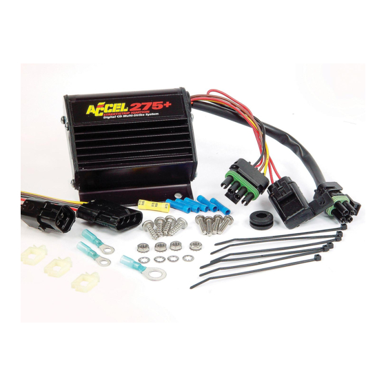
Advertisement
DIGITAL MULTI-STRIKE CD IGNITION CONTROLLER
GENERAL INFORMATION
The features of the 275+ and 300+ Ignitions are the same,
with one exception: the 300+ includes a single stage RPM
limiter. You can set various RPM limits using switches that
are accessible through the end plate. See page 4 of this
instruction book for more information about the rev
limiting features of the 300+.
Battery
The 275+ and 300+ Ignition Controls operate on any
n e ga t ive ground, 12 volt electrical system with a distributor.
It will also work with 16 volt batteries and can withstand a
momentary spike of 24 volts in case of jump starts. This
system delivers full voltage with a supply of 10-18 volts,
and operates with a supply voltage as low as 8 volts.
If your application does not use an alternator, allow at least
15 amp/hour for every half hour of operation. If you crank
the engine with the same battery or other accessories,
such as an electric fuel or water pump, increase the
amp/hour rating.
Coils
For optimum performance with your 275+ or 300+ Ignition
Controls, we recommend ACCEL P/N 140019 Coil, as well
as most stock coils or aftermarket coils designed as
stock replacements or CD-type coils.
NOTE: Do not use ACCEL's Drag Race Coil P/N 140010.
Tachometers
The green wire on the 275+ and 300+ Ignition Controls
provides a trigger signal for tachometers, shift lights, or
other add-on RPM activated devices. This wire produces a
12 volts square wave signal with a 20% duty cycle.
Some vehicles with factory tachometers may require a tach
adapter to work with the 275+ and 300+ Ignition Controls. If
your GM vehicle uses an inline filter, it may cause the tach
to drop to zero on acceleration. If this occurs, bypass the
filter. For more information on tachometers, see page 3.
Spark Plugs
Using the correct spark plug and heat range is important
for optimum performance. Because there are so many
variables to consider, we suggest starting with your engine
manufacturer's spark plug recommendation. From there,
you can experiment with small changes in plug gap
and heat range to obtain the best performance from
your engine.
Foreign Vehicles
Because of modern fuel injection systems, some foreign
vehicles may require a tachometer/fuel injection adapter to
work with the 275+ or 300+ Ignition Controls.
©2007 by ACCEL
INSTALLATION INSTRUCTIONS
275+ & 300+ STREET / STRIP
NOTE: Do not install the 275+ or 300+ Ignition Controls
in any vehicle that is originally equipped with a
CD ignition control.
Spark Plug Wires
High quality, spiral wound wire and proper routing are
essential to the operation of the 275+ and 300+ Ignition
Controls. This type of wire provides a good path for
the spark to follow while minimizing electromagnetic
interference (EMI).
NOTE: Do not use solid core spark plug wires with the
275+ or 300+ Ignition Controls.
Routing
Wires should be routed away from sharp edges, moving
objects, and heat sources. Wires that are next to each other
in the engine's firing order should be separated. For
example, in a Chevy V8 with a firing order of 1- 8 - 4 - 3 - 6 - 5 - 7-2,
the #5 and #7 cylinders are positioned next to each other
on the engine as well as in the firing order. Voltage from
the #5 wire could jump to the #7 wire. This could cause
detonation and engine damage.
For added protection against cross-fire, ACCEL offers
PRO SLEEVE insulated sleeving. PRO SLEEVE is a glass
woven, silicone coated protective sleeve that slides over
your plug wires. It also helps reduce damage from heat
and sharp objects.
MISCELLANEOUS INFORMATION
Sealing
Do not attempt to seal the 275+ or 300+ Ignition Controls.
All of the circuits of a 275+ and 300+ receive a conformal
coating of sealant that protects the electronics from
moisture. Sealing the 275+ and 300+ will not allow any
moisture that seeps in through the grommets to drain and
may result in corrosion.
Welding
To avoid any damage to the 275+ or 300+ Ignition Controls
when welding on the vehicle, disconnect both the 4-pin flat
and 4-pin square connectors. It is also a good idea to
disconnect the tachometer ground wire as well.
Distributor Cap and Rotor
We recommend installing a new distributor cap and rotor
when installing the 275+ or 300+ Ignition Controls. Be sure
the cap is clean inside and out, especially the terminals and
rotor tip. On vehicles with smaller caps, it is possible for
the air inside the cap to become electrically charged
causing crossfire which can result in misfire. You can
prevent this by drilling a couple of vent holes in the cap.
INST275/300
1
Advertisement
Table of Contents

Summary of Contents for Accel 300+
- Page 1 CD-type coils. woven, silicone coated protective sleeve that slides over your plug wires. It also helps reduce damage from heat NOTE: Do not use ACCEL’s Drag Race Coil P/N 140010. and sharp objects. Tachometers The green wire on the 275+ and 300+ Ignition Controls...
-
Page 2: Routing Wires
Drill the holes between terminals at rotor height, facing away WIRING from the intake. If needed, place a small piece of screen over the holes to act as a filter. Wire Length All of the wires of the 275+ or 300+ Ignition Controls may be 275+ Diagnostic LED shortened as long as quality connectors are used or soldered Behind the end panel of your 275+ ignition there is a red LED... -
Page 3: Pre-Start Checklist
If your tachometer fails to operate with the 275+ or 300+ the ignition for spark. Mallory offers an Ignition Tester (P/N installed, you may need an ACCEL or Mallory tach adapter. 28357) that allows you to check the entire ignition Before purchasing a tach adapter, try connecting your system while it is installed in the vehicle. -
Page 4: Checking For Spark
UP position. 5. With a small jumper wire, short the 275+ or 300+ Ignition CAUTION: Using the ACCEL 300+ with an external RPM Control’s green and violet magnetic pickup wires together. limiter AND switch #4 in the DOWN position could cause... - Page 5 ACCEL 300+ to a 1984-95 GM HEI remote coil (Small distributor cap) CUSTOM FIT PART NUMBER 49322 & 49323 Use this wiring harness to connect your ACCEL 300+ to a 1973-91 GM HEI In-Cap Distributor with the module in place...
- Page 6 ACCEL 300+ to a 1993-95 Camaro or Firebird (LT1) CUSTOM FIT PART NUMBER 49325 Use this harness to connect your ACCEL 300+ to a 1992-95 Corvette LT1 or Tach 1994-95 GM full size including Impala SS Adapter (ACCEL P/N 49365)
- Page 7 CUSTOM FIT PART NUMBER 49326 Use this harness to connect your ACCEL 300+ to a 1984-98 Ford with EEC-IV except EDIS If Needed CUSTOM FIT PART NUMBER 49327 Use this harness to connect your ACCEL 300+ to a 1996-97 LT1/LT4...
- Page 8 Note: 1998-99 Dodge Truck/Jeep applications also require the use of Coil Adapter Harness P/N 140021AH. CUSTOM FIT PART NUMBER 49329 Use this harness to connect your ACCEL 300+ to 1996-99 Chevy/GMC Vortec truck engine with single coil ACCEL Is a division of Prestolite Performance.
Need help?
Do you have a question about the 300+ and is the answer not in the manual?
Questions and answers
Working on a 1975 bronco that has an accel 300+ ignition system that was installed 10 years ago. Vehicle sat for last 7 years. There is no spark. At the coil there is constant ground on brown wire and while cranking has pulsing power on yellow wire. I think the module has failed.