Table of Contents
Advertisement
Quick Links
Advertisement
Table of Contents

Summary of Contents for K1EL Morse Tutor Board
- Page 1 Morse Tutor Board User Manual v1.1 www.k1el.com...
-
Page 2: Morse Tutor Board (Mtb) Features
The MTB is implemented in a Microchip PIC16F1825 microcontroller and utilizes a special version of the K1EL K16 keyer core which provides a wide range of features. Setup commands are directly entered on the paddles in Morse code. All settings and messages are stored in nonvolatile memory so that they are preserved when the keyer is turned off. - Page 3 MTB will play them in order. • Simplified Beacon Formatting This message is all that is required to setup a repeating 15 second beacon: /B15 K1EL BCON • Easy Beacon Any message slot can be turned into a beacon without having to add the special /B embedded command.
-
Page 4: Morse Tutor Functional Block Diagram
K1EL Morse Tutor Board Morse Tutor Functional Block Diagram Figure 1 is a block diagram of the MTB. As shown, there are five touch pads, a sidetone speaker, rotary encoder speed control/pushbutton, and an RCA keying port that can connect to other MTBs in a network configuration or to key a transceiver/transmitter. -
Page 5: Morse Tutor Board Kit
K1EL Morse Tutor Board Morse Tutor Board Kit The MTB keyer kit consists of a single board with all through-hole components for easy assembly. It’s a good idea to read through the assembly instructions before starting. Please follow the steps in the order presented for best results. - Page 6 K1EL Morse Tutor Board Figure 3 - MTB component identification Start by attaching the four stick-on rubber feet to the bottom side of the board: Figure 4 – Rubber feet in place Morse Tutor Manual – v1.1 9/19/2018 Page 6...
- Page 7 K1EL Morse Tutor Board Install and solder all five ¼ watt resistors, their color codes are listed in the parts inventory on page 5. We recommend verifying resistor values with an ohmmeter. Install and solder two .1uF and three .01 uF capacitors.
- Page 8 K1EL Morse Tutor Board Figure 6 – Socket, 2 pin headers, Q1, Q2, speaker, and LED installed Snap the RCA connector into place and be sure it is fully seated into the board before soldering. It will take some extra heat to solder this part in so don’t rush it. Be careful here since the body of the RCA jack will get extremely hot while it’s being soldered, so don’t touch and avoid a painful burn.
- Page 9 K1EL Morse Tutor Board Install the battery holder. Two strips of double sided tape hold the holder to the PC board. Peel off the protective film from each tape and press the holder in place, align the holder with the board’s silk screen.
-
Page 10: Mtb Test Procedure
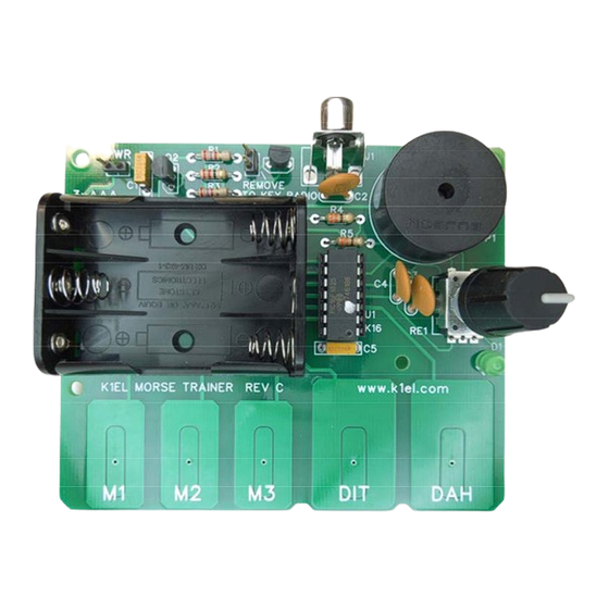
K1EL Morse Tutor Board Figure 10 – Assembled Morse Tutor Board MTB Test Procedure The simplified drawing below is labeled to make it easy to identify MTB’s main features. At this point neither the power or network control jumpers should be installed. We will start by installing three AAA batteries in the holder paying attention to battery polarity. -
Page 11: Output Keying Considerations
K1EL Morse Tutor Board After calibration, you should find that pressing the DIT or DAH pads will cause the keyer to automatically send a steam of Morse dits or dahs over the sidetone speaker. If you press both pads, the keyer will send alternating dits and dahs. -
Page 12: Mtb Schematic Diagram
K1EL Morse Tutor Board MTB Schematic Diagram Figure 29 – Morse Tutor Board Schematic Morse Tutor Manual – v1.1 9/19/2018 Page 12... -
Page 13: Operating The Mtb Keyer
K1EL Morse Tutor Board Operating the MTB Keyer Command Mode Normally a novice Morse student will not need to make any changes to MTB settings other than change speed which is done by turning the speed control. As the student improves, they will want to experiment and learn more about the MTB. - Page 14 K1EL Morse Tutor Board I[nn] – Set Letterspace Adjustment: nn is a value 0 to 31 that specifies an additional letterspace delay to be applied between letters. Multiply nn by two to arrive at the actual adjustment percentage. For example a value of 7 applies 14% additional letterspace between letters.
- Page 15 K1EL Morse Tutor Board R [pb] – Review a message without transmitting: After the R command is entered the MTB will respond with an E. You then press the slot you wish to play (M1-M5). The contents will be sent in sidetone only. An empty slot will play as MT.
- Page 16 K1EL Morse Tutor Board Extended Command List An additional set of commands is located in a sub menu. Extended commands require two entries, an X followed by a sub command. This is the Extended Command procedure in detail: Press and hold the rotary encoder down and the MTB will respond with an R Enter an X and the MTB will respond with an E (command request) Enter desired Extended Command with additional parameters, if required.
-
Page 17: Speed Encoder Configuration
K1EL Morse Tutor Board The receive/respond practice command is P. The level is entered just like the G command described above. Enter P, MTB responds with E, you enter the level; E, I, S, or H. (1 dit, 2 dits, 3 dits, or 4 dits). -
Page 18: Message Functionality
K1EL Morse Tutor Board Message Functionality Messages are loaded by first pushing the rotary encoder button down until MTB responds with an R, and then pressing the message pad M1, M2, M3, or encoder PB (M4) to select the memory slot you wish to enter. -
Page 19: Message 5 Access
UR RST IS /P QSL will pause to allow the user to enter the RST then resume automatically /K05 /W10 VVV DE K1EL will key down for 5 secs, wait 10 secs, and then send VVV DE K1EL CQ CQ CQ DE /M /M /M will send a 3x3 CQ using the user callsign CQ CQ CQ DE K1/I10TMT/I00 K will send message with 20% extra space in TMT. -
Page 20: Power On And Off
K1EL Morse Tutor Board A serial number decrement command D is provided (see page 13) but this is not used very often. There is a third way to decrement a serial number, that is with a /D command embedded in a message. A message can be built that predecrements the serial number before sending it. -
Page 21: Mtb Command Cheat Sheet
K1EL Morse Tutor Board MTB Command Cheat sheet Immediate Command List: Toggle sidetone on/off Load 4 digit serial number Easy beacon Receive/Resend practice Set command speed Query: Report current settings Decrement serial number Review message with transmit muted Swap message banks... -
Page 22: Mtb Tutorial
K1EL Morse Tutor Board MTB Tutorial Start with power on: Push down on the rotary encoder (encoder PB) until the MTB outputs the letter R to let you know it’s ready. Touching the paddle pads will generate dits and dahs both in sidetone and keyed output. If you press any of the message pads, the MTB will send an MT meaning the message slot is eMpTy. -
Page 23: Manual Revision History
/B60/K05 BCON DE K1EL NH Press M2 to start the beacon. A 5 second key down is sent first followed by BCON DE K1EL NH. /B60 specifies that the beacon will be repeated every 60 seconds. To cancel a beacon simply press the encoder PB and MTB will stop the loop and respond with an X to let you know the beacon was cancelled. -
Page 24: Appendix A - Kit Construction Hints
K1EL Morse Tutor Board Appendix A - Kit Construction Hints 1. Find a good workspace. It is essential that you have a good place to work on your kit, You will need room to spread out your parts and have access to tools. Good lighting and ventilation is essential. -
Page 25: Appendix C - Soldering Basics
K1EL Morse Tutor Board Appendix C - Soldering Basics Insert component leads into PCB holes and bend them back slightly to hold the part in place. You can either trim the lead now or wait till after the joint is soldered. I usually install several parts at one time and then solder and trim multiple leads. - Page 26 K1EL Morse Tutor Board 5. Remove the solder and then remove the iron. Fig C3 - Remove the solder 6. Allow the joint to cool and visually inspect for defects or other problems. You should have a solder joint with a bright shiny finish and a profile like that shown in the middle picture below. Make sure you use enough heat so that solder flows around both the lead and pad.
-
Page 27: Table Of Contents
K1EL Morse Tutor Board Table of Contents MORSE TUTOR BOARD (MTB) FEATURES ................ 2 MORSE TUTOR BOARD (MTB) FEATURES ................ 2 MORSE TUTOR DESCRIPTION (MTB) ................. 2 MORSE TUTOR FUNCTIONAL BLOCK DIAGRAM ............. 4 MORSE TUTOR BOARD KIT .................... 5 MORSE TUTOR BOARD ASSEMBLY .................. 5 Morse Tutor Parts Inventory ........................ 5 MTB TEST PROCEDURE ....................... 10 ... - Page 28 K1EL Morse Tutor Board J [nn] ‐ Paddle Sample Delay ........................ 14 K ‐ Set Keying Mode .......................... 14 L – Enable/Disable LED ........................ 14 M – Mute Transmit .......................... 14 N [nnnn] ‐ Load 4 Digit Serial Number: .................... 14 P[n] – Start Echo Practice ........................ 14 Q ‐ Query MTB Current Settings ...................... 14 R [pb] – Review a message without transmitting: ................ 15 S [nn] ‐ Set Morse Speed in WPM ...................... 15 U ‐ Toggle Autospace Mode Off and On .................... 15 V ‐ Toggle 50% tune duty cycle ...................... 15 W[nn] – Key Weighting: ........................ 15 ...
- Page 29 K1EL Morse Tutor Board SPEED ENCODER CONFIGURATION ................. 17 MESSAGE FUNCTIONALITY .................... 18 Gap (Extra Space) Insertion ......................... 18 Word Space Insertion .......................... 18 ‘Two Press’ Message Button Functionality or .................. 19 Message 5 Access .......................... 19 Embedded Message Command List ...................... 19 Embedded message command table .................... 19 Embedded Command Examples: ...................... 19 Quick Tune Command ......................... 19 Quick Serial Number Decrement ...................... 19 POWER ON AND OFF ...................... 20 PRESERVE SETTINGS ...................... 20 ...
Need help?
Do you have a question about the Morse Tutor Board and is the answer not in the manual?
Questions and answers