Table of Contents
Advertisement
Quick Links
Operating Instructions
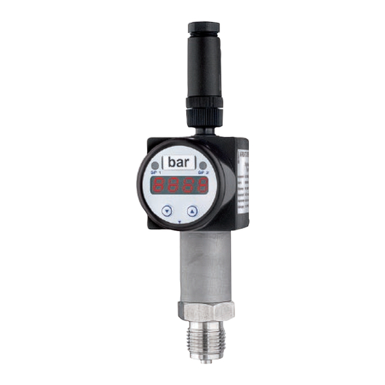
Digital Display and Switching Module DAS/DASA
Contents
1.
1.1
1.2
1.3
2.
3.
4.
4.1
4.2
5.
6.
7.
8.
9.
10.
11.
1.
1
• The manual is aimed at specialists and semi-skilled
2
personnel.
2
• Please read the instructions carefully before carry-
2
ing out any operation and keep the specified order.
2
• Thoroughly read and understand the information in
3
chapter 2 "Safety Instructions".
4
4
If you have any problems or questions, please contact
4
your supplier or contact us directly at:
5
5
10
10
10
ARMANO Messtechnik GmbH
11
Location Beierfeld
12
Am Gewerbepark 9 • 08344 Grünhain-Beierfeld
Tel.: +49 3774 58 - 0 • Fax: +49 3774 58 - 545
mail@armano-beierfeld.com
Location Wesel
Manometerstraße 5 • 46487 Wesel-Ginderich
Tel.: +49 2803 9130 - 0 • Fax: +49 2803 1035
mail@armano-wesel.com
www.armano-messtechnik.com
Information on This Operating Instruction
B26
04/19
Advertisement
Table of Contents

Summary of Contents for ARMANO DAS
-
Page 1: Table Of Contents
Operating Instructions Digital Display and Switching Module DAS/DASA 04/19 Contents Information on This Operating Instruction Information on This Operating Instruction • The manual is aimed at specialists and semi-skilled Pictographs Used in This Manual personnel. Exclusion of Liability • Please read the instructions carefully before carry- General Information ing out any operation and keep the specified order. -
Page 2: Pictographs Used In This Manual
The personnel must be aware of this manual and have access to it at all times. • The electrical connection shall be carried out by a fully qualified electrician only. B26 • 04/19 • GB • p. 2 of 12 • www.armano-messtechnik.com... -
Page 3: Device Description
Warnings, which are specifically relevant to individual operating procedures or activities, are to be found at the beginning of the relevant sections of this operating instruction. menu UP menu DOWN www.armano-messtechnik.com • p. 3 of 12 • GB • 04/19 • B26... -
Page 4: Technical Data
− supply − devices are equipped with a green LED for switch point 1 and a yellow LED for switch point 2 (DAS only). If the respective LED lights up, the switch point has switch point 1 been reached and the switching output is active. -
Page 5: Installation
The screw length was determined for a Hirschmann cable box type GDM 3009. If you use another cable box, ensure that an appropriate screw is used. www.armano-messtechnik.com • p. 5 of 12 • GB • 04/19 • B26... - Page 6 The setting range is between 0.3 to 30 seconds. To complete the setting, press both control keys si- multaneously. B26 • 04/19 • GB • p. 6 of 12 • www.armano-messtechnik.com...
- Page 7 After pressing both control keys simultaneously in the menu shown, the value to acti- vate switching output 2 can be set. To complete the setting, press both control keys si- multaneously. www.armano-messtechnik.com • p. 7 of 12 • GB • 04/19 • B26...
- Page 8 To complete the setting, press both control keys si- multaneously. Æ Select the menu “PAoF”. Æ Press both control keys simultaneously. Æ Enter 0238 to select the special function. Æ Press both control keys simultaneously again. B26 • 04/19 • GB • p. 8 of 12 • www.armano-messtechnik.com...
- Page 9 4,000 mA, may occur. Resulting The following pattern appears in the display: from this, the DAS / DASA might indicate a signal val- ue deviating from the set lower range value. The DAS / DASA control software includes a function for adjusting this indication: Æ...
-
Page 10: Maintenance / Cleaning, Storage And Transport
• Avoid impacts or strong vibrations. • Protect the device against damage caused by ex- ternal influences. • During storage, the specified temperature limits must not be exceeded. B26 • 04/19 • GB • p. 10 of 12 • www.armano-messtechnik.com... -
Page 11: Annex: Menu System
HILO menu: CP1/HY1 menu: D2of Information concerning switch point 2 (S2) and comparison or hysteresis mode CP2/HY2 apply to model DAS only. www.armano-messtechnik.com • p. 11 of 12 • GB • 04/19 • B26... -
Page 12: Declaration Of Conformity
Tel.: +49 2803 9130 – 0 Bernd Vetter Fax: +49 3774 58 – 545 Fax: +49 2803 1035 mail@armano-wesel.com Geschäftsführender Gesellschafter / Managing Director mail@armano-beierfeld.com www.armano-messtechnik.de © 2019 ARMANO Messtechnik GmbH · Technical changes, replacement of materials and printing errors excepted! www.armano-messtechnik.com...
Need help?
Do you have a question about the DAS and is the answer not in the manual?
Questions and answers