
Subscribe to Our Youtube Channel
Summary of Contents for MCC 68AC353-102 MICROMAX
- Page 1 T-348 Manual OPERATION AND SERVICE 68AC353-102 MICROMAX T-348 REV. 07/2012 © 2012 Mobile Climate Control...
-
Page 2: Table Of Contents
TABLE OF CONTENTS SAFETY SUMMARY ............. . . Safety-1 DESCRIPTION . - Page 3 TABLE OF CONTENTS - Continued 2.1.1 Power to Logic Board ..............2.1.2 Starting .
- Page 4 TABLE OF CONTENTS - Continued OPENING TOP COVER (EVAPORATOR) ........REMOVING TOP COVER (CONDENSER) .
- Page 5 TABLE OF CONTENTS - Continued 4.18 REPLACING SENSORS AND TRANSDUCERS ....... 4-18 4.19 LOGIC BOARD REPLACEMENT .
- Page 6 Figure 5-3. Wiring Schematic - Power Circuit (PM Motors) - 68AC353-102, 102-4, 102-5 ..Figure 5-4. Wiring Schematic - Legend (Brushless Motors) (CAN) - 68AC353-102-1, 102-3, 102-6 Figure 5-5. Wiring Schematic - Control Circuit (Brushless Motors) (CAN) - 68AC353-102-1, 102-3, 102-6 . .
-
Page 7: Safety Summary
SAFETY SUMMARY GENERAL SAFETY NOTICES The following general safety notices supplement the specific warnings and cautions appearing elsewhere in this manual. They are recommended precautions that must be understood and applied during operation and maintenance of the equipment covered herein. A listing of the specific warnings and cautions appearing elsewhere in the manual follows the general safety notices. - Page 8 SPECIFIC WARNING AND CAUTION STATEMENTS The statements listed below are applicable to the refrigeration unit and appear elsewhere in this manual. These recommended precautions must be understood and applied during operation and maintenance of the equipment covered herein. SPECIFIC WARNINGS AND CAUTIONS WARNING Be sure to observe warnings listed in the safety summary in the front of this manual before performing maintenance on the hvac system...
- Page 9 CAUTION To prevent trapping liquid refrigerant in the manifold gauge set be sure set is brought to suc tion pressure before disconnecting. CAUTION Use care when checking/manipulating wires/plugs attached to the Logic Board. Damage to the board or wiring harness can occur. Safety-3 ©...
-
Page 10: Description
SECTION 1 DESCRIPTION 1.1 INTRODUCTION curvature of the bus roof. The assemblies available are identified as the 10 M radius cover and the 6.5 M This manual contains Operating Instructions, radius cover. Service Instructions and Electrical Data for the 1.3.2 Condenser Electrical Kit Model 68AC353 Air Conditioning and Heating equipment furnished by Mobile Climate Control as The 68AC353 condenser kits are wired for either 24... - Page 11 1.3.10 Air Exchange Kit 1.3.11 Controller Kit The unit will be fitted with a fresh air exchange The Micromax Controller operates the system assembly or an air exchange blank off plate. Fresh air through one of two relay boards and may be exchange assemblies may be of the 25% or 50 % interrogated through the optional CAN +/- Data opening.
-
Page 12: Condenser Electrical Kit
Table 1-1 Option Legend OPTION DESCRIPTION OPTION DESCRIPTION Condenser Skins Kit Evaporator Connection Kit S/D Standard Cover (R10M) Left - ORS Cover (R6.5M) Right - ORS Condenser Electrical Kit Left - ORS With Out Front Box Connection Condenser Electrical Kit Condenser Electrical Kit / Brushless Evaporator Connection Kit - Indash Condenser Fan Kit... -
Page 13: General Description
Table 1-3 Additional Support Manuals MANUAL/FORM NUMBER EQUIPMENT COVERED TYPE OF MANUAL T-348PL 68AC353 Parts List 62-10699 Micromate Diagnostic Tool (Card) Dash--Air Option Compressor Main Harness Discharge Check Valve Driver Control Refrigerant Lines Power Harness Compressor Harness Main Circuit Breaker Electronics Boards - Power Relay Battery Liquid Line Solenoid... -
Page 14: Rooftop Unit
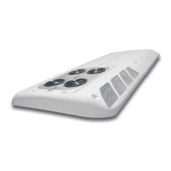
preventing the flow of high pressure liquid from the Micromax electronics, and the Fresh Air System. All condenser back into the compressor. components are accessible by lifting the condenser and evaporator top covers. Descriptions of the 1.4.3 Rooftop Unit systems are provided in the following sub The Rooftop unit (see Figure 1-2) is comprised of paragraphs. -
Page 15: Figure 1-3 Condensing Section Components
1.4.4 Condensing Section The condensing section (Figure 1-3) includes the the tubes; this results in condensation of the cover, left and right condenser coils, fan and motor refrigerant into a liquid. assemblies, receiver, service valves and an ambient The receiver collects and stores liquid refrigerant. temperature sensor.. -
Page 16: Fresh Air System
1.4.5 Evaporator Section The evaporator section (Figure 1-4) includes the filter-drier removes moisture and debris from the evaporator coils, six blower and motor assemblies, liquid refrigerant before it enters the thermostatic evaporator coil assemblies, heater coil assemblies, expansion valve in the evaporator assembly. Service filter drier, a thermostatic expansion valve, liquid line valves enable isolation of the filter-drier for service. -
Page 17: System Operating Controls And Components
1.5 REFRIGERATION SYSTEM COMPONENT SPECIFI- open and close the damper to allow addition of fresh CATIONS air into the air entering the evaporator coil. For additional information on air flow, refer to paragraph a. Refrigerant Charge 1.9. R-134a15.8 Lb (7.17 kg) 1.4.7 System Operating Controls And Components b. -
Page 18: Electrical Specifications - Sensors And Transducers
1.7 ELECTRICAL SPECIFICATIONS - SENSORS AND b. Fuses and Circuit Breakers TRANSDUCERS The system is protected against high current by an a. Suction and Discharge Pressure Transducer OEM supplied 125 amp fuse or circuit breaker. Independent fuses or circuit breakers protect each Supply Voltage: 4.5 to 5.5 vdc (5 vdc nominal) evaporator blower motor and condenser motor Supply current: 8 mA maximum... -
Page 19: Air Flow
1.9 AIR FLOW The paths for ambient air through the condenser and coach air through the evaporator are illustrated in Figure 1-5. COIL RETURN EVAPORATOR COIL EVAPORATOR COIL AIR FILTERS HEATER COIL HEATER COIL FRESH AIR COACH RETURN AIR FILTER EVAPORATOR Return To Ambient Through Fan... -
Page 20: Air Conditioning Refrigeration Cycle
1.10 AIR CONDITIONING REFRIGERATION CYCLE When air conditioning (cooling) is selected by the the refrigerant enters the filter-drier where an controller, the unit operates as a vapor compression absorbent keeps the refrigerant clean and dry. system using R-134a as the refrigerant (See From the filter-drier, the liquid refrigerant then flows Figure 1-6). -
Page 21: Figure 1-6 Refrigerant Flow Diagram
Legend Discharge CONDENSER Liquid Suction Refrigerant Flow Discharge Service Valve Discharge Check Valve Service Port, Discharge High Pressure Switch Discharge Pressure Transducer Low Pressure Switch (Crankcase) Dash Air Liquid Line (Option) Suction Service Valve/Port Dash Air Suction Tee (Option) Suction Pressure Transducer Evaporator Coil Thermal Expansion Valve (TXV) TXV Bulb... -
Page 22: Heating Cycle
1.11 HEATING CYCLE Heating circuit (See Figure 1-6) components is circulated through the heating circuit by the engine furnished by Mobile Climate Control include the and an auxiliary boost water pump. When the heat heater coils and a solenoid operated heat valve. valve solenoid is energized, the valve will open to Components furnished by the bus manufacturer allow engine coolant to flow through the heater coil. -
Page 23: Control Panel With Gr60 Relay Board
1.12 CONTROL PANEL WITH GR60 RELAY BOARD Logic Board (See Figure 1-10) Fresh Air Relay Board - GR60 (See Figure 1-11) Terminal Block (TB) Power Relay (ON) Figure 1-8 Control Panel 1--14 © 2012 Mobile Climate Control T-348 Rev. 07/2012... -
Page 24: Control Panel
1.13 CONTROL PANEL With CAN With/Out CAN Logic Board (See Figure 1-10) Fuses Relay Board (See Figure 1-12) Fresh Air Logic Board, Data Communications Power Terminal Block (PTB) (See Figure 1-13 Terminal Block (TB) Power Relay (ON) Ground Figure 1-9 Control Panel 1--15 ©... -
Page 25: Logic Board
1.14 LOGIC BOARD Logic board power in. Diagnostics interface (RS232, DB9). Micromate Display interface. Not used Manual control inputs. D2 Blinks once per second in normal operation. Interlock Inputs On steady to indicate alarms detected. (WTS, low side pressure switch etc.) D3 Off In normal operation, blinks out alarm Relay board interface. -
Page 26: Relay Board - Gr60, 24Vdc
1.15 RELAY BOARD - GR60, 24VDC Figure 1-11. Relay Board - GR60 Energizes evaporator fans 1 & 2 in high speed K12 Connects the negative side of condenser fan or evaporator fans 1,2,3 & 4 in low speed. 5 to ground in high speed. Connects the Energizes evaporator fans 3 &... -
Page 27: Relay Board - Gr60, 24Vdc (Continued)
Figure 1-11. Relay Board - GR60 (Continued) 1.15 RELAY BOARD - GR60, 24VDC (Continued) e. Thermal Circuit Breakers g. LEDS CB 1 Evaporator Fan #1. 15 Amp. D 2 Relay K1 output active (evaporator fans 1,2,3 & CB 2 Evaporator Fan #2. 15 Amp. -
Page 28: Relay Board, 24Vdc
1.16 RELAY BOARD, 24VDC Figure 1-12. Relay Board a. Relays d. LEDS Energizes evaporator fans in low speed D 2 Evaporator fans output active -- high speed Energizes evaporator fans in high speed D 6 Evaporator fans output active. (not energized in low speed). K 7 Energizes condenser fans in low speed D26 Condenser fans output active. -
Page 29: Logic Board, Data Communications
1.17 LOGIC BOARD, DATA COMMUNICATIONS Function Remarks Function Remarks +24VDC In Power In RS--232 TXD HVAC Data Port 24VDC Return Ground RS--232 RXD HVAC Data Port Alt, CAN_H CAN Port #2 (Optional) LED Out Status Indicator (Optional) Alt, CAN_L CAN Port #2 (Optional) RS--232 Gnd HVAC Data Port LED Gnd... -
Page 30: Control Panel (Diagnostic Module)
1.18 CONTROL PANEL (Diagnostic Module) Display HEAT (Only) Button DOWN Button - decrease selection FAN SPEED Button UP Button - increase selection FRESH AIR Button VENT (Only) Button TEMPERATURE (Inside / Outside) AUTO Button (Automatic Control) Button COOLING (Only) Button ON/OFF Button Figure 1-14 Micromate Control Panel 1--21... -
Page 31: Operation
SECTION 2 OPERATION 2.1 STARTING, STOPPING AND OPERATING INSTRUC- Figure 1-14) to illuminate the indicator light and TIONS place the system in that mode of operation. 4. If low or high speed evaporator fan speed is de 2.1.1 Power to Logic Board sired, press the FAN SPEED button to illuminate Before starting, electrical power must be available the indicator light and bring speed to the desired... -
Page 32: Pre-Trip Inspection
2.2 PRE-TRIP INSPECTION of a logic board (Figure 1-10), relay board (Figure 1.15 or Figure 1.16), and manual operator switches. After starting system, allow system to stabilize for ten The logic board regulates operational cycles of the to fifteen minutes and check for the following: system by energizing or de-energizing Relay Board a. -
Page 33: Temperature Control
2.3.1 Temperature Control When operating in cooling, the unloaders are used to reduce system capacity as return air temperature Temperature is controlled by maintaining the return approaches set point. Operation of the unloaders air temperature measured at the return air grille. balances system capacity with the load and thereby prevents overshoot from set point. -
Page 34: Evaporator Fan Speed Selection
2. Compressor Unloader UV2 Relay. When suction pressure decreases below 135 PSIG. High speed will pressure decreases below 23 psig, unloader UV2 is also remain activated if a high pressure alarm has energized unloading the second compressor cyl been activated and operation has not been locked inder bank;... -
Page 35: Control
It is recommended that MCC Service or 2.4.2 Diagnostic Mode Engineering is contacted before any The diagnostic mode can be entered by pressing the control configuration is changed. -
Page 36: Test Mode
2.4.4 Test Mode Table 2-4. Controller Test List With the system in normal operation, the controller TEST OUTPUT STATE may be placed in the test mode, by doing the All Relays following: Evaporator Fans High a. Enter the diagnostic mode by pressing the UP and Evaporator Fans Low DOWN arrow keys simultaneously for 3 seconds. -
Page 37: Table 2-5. Parameter Codes
Table 2-5. Parameter Codes CODE CODE NAME DESCRIPTION Return Air This value is the temperature measured by the return air sensor. If the sensor is shorted it Temperature will display CL. If it is open circuited it will display OP. Coil Temperature Not used. - Page 38 Table 2-5. Parameter Codes - Continued Code Code Name Description Compressor Hours High This is the number of hours of operation that the compressor has run with the clutch energized in thousands. Compressor Hours Low This is the number of hours of operation that the compressor has run with the clutch energized in hundreds, tens and ones.
- Page 39 Table 2-5. Parameter Codes - Continued Code Code Name Description Compressor Minimum When parameter is set to OFF, the minimum compressor on time will be 5 minutes. On time When set to ON, the minimum compressor on time will be 1 minute. Enable Hidden Alarm This value determines if alarms A33 and A34 are displayed.
-
Page 40: Troubleshooting
SECTION 3 TROUBLESHOOTING CAUTION Do not under any circumstances attempt to service the microprocessor. Should a problem de velop with the microprocessor, replace it. 3.1 SELF DIAGNOSTICS number of times that the Logic Board STATUS and CODE LED's (see Figure 1-10) flash A self test is performed by the Micromax Logic simultaneously. -
Page 41: Exit Alarm Queue
3.2.5 Exit Alarm Queue 9. If no digits are streamed, STOP. The Micromate Logic unit or the interface connection is defect To exit the alarm queue press the ON/OFF key ive. once, or if no key is pressed for 30 seconds it will reset to normal mode. -
Page 42: Table 3-2 Alarm Codes
Table 3-2 Alarm Codes ALARM TITLE CAUSE REMEDY CONTROLLER RESPONSE Coil Freeze Coil temperature is less Check causes of coil An alarm will be generated than 32°F and the com freezing. (Refer to sec and the system will shut pressor is operating. tion 3.3.7) down. - Page 43 Table 3-2. Alarm Codes - Continued ALARM TITLE CAUSE REMEDY CONTROLLER RESPONSE Breaker Trip/Blown Fuse A breaker/fuse on the Check breakers/fuse for Alarm will be generated. Alarm relay board has tripped tripped device. Repair or a fan relay has failed. short and reset/replace breaker/fuse.
-
Page 44: Figure 4-12 Compressor
Table 3-3. General System Troubleshooting Procedures INDICATION/ REFERENCE POSSIBLE CAUSES TROUBLE SECTION 3.3.2 System Will Not Cool Compressor will not run Active system alarm V-Belt loose or defective Check Clutch coil defective Check/Replace Clutch malfunction Check/Replace Compressor malfunction See Table 1-3 Electrical malfunction Coach power source defective Check/Repair... -
Page 45: Control System Malfunction
Table 3-3 General System Troubleshooting Procedures - Continued INDICATION/ REFERENCE POSSIBLE CAUSES TROUBLE SECTION 3.3.5 Abnormal Noise Or Vibrations - Continued Condenser or evaporator fans Loose mounting hardware Check/Tighten Defective bearings Replace Blade interference Check Blade missing or broken Check/Replace 3.3.6 Control System Malfunction Will not control Sensor or transducer defective... -
Page 46: Service
SECTION 4 SERVICE WARNING Be sure to observe warnings listed in the safety summary in the front of this manual before performing maintenance on the hvac system. WARNING Read the entire procedure before beginning work. Park the coach on a level surface, with parking brake applied. -
Page 47: Figure 4-1 Opening Top Cover (Evaporator)
4.2 OPENING TOP COVER (EVAPORATOR) b. Grasp the cover section under the bottom edge and lift up. To open either side of the evaporator assembly cover c. Locate metal rod (prop) secured behind the evap do the following: (See Figure 4-1.) orator motor assemblies. -
Page 48: Figure 4-3 Suction Or Discharge Service Valve
4.4 SUCTION AND DISCHARGE SERVICE VALVES 1. If the manifold gauge/hose set is new or was exposed to the atmosphere it will need to be eva The suction and discharge service valves (Figure 4-3) cuated to remove contaminants and air as follows: are provided with a double seat and a gauge port, 2. -
Page 49: Figure 4-4 Manifold Gauge Set (R-134A)
c. Start the system and run in cooling. Stop the unit Low Pressure High Pressure when suction reaches 2 psig (0.14 Bar). Gauge Gauge d. Frontseat the compressor suction service valve (6) to trap refrigerant in the high side of the system be tween the compressor suction service valve and the charge isolation valve. -
Page 50: Figure 4-5 Compressor Service Connections
4.5.2 Refrigerant Removal From An Inoperative Com- d. Using refrigerant hoses designed for vacuum ser pressor. vice, connect a vacuum pump to center connec tion of manifold gauge set. Evacuate compressor To remove the refrigerant from a compressor that is to 500 microns. -
Page 51: Figure 4-6 Service Connections
CONDENSER Legend Discharge Liquid Suction Refrigerant Flow EVAPORATOR COMPRESSOR Discharge Service Valve Liquid Line Solenoid Valve Service Port, Discharge Liquid Line Sightglass Discharge Pressure Transducer Filter Drier Discharge Check Valve Filter Drier Outlet Service (King) Valve High Pressure Switch Manifold Gauge Set Service Port, Suction Service Valve Vacuum Pump Suction Pressure Transducer... -
Page 52: Pump Down An Operable Compressor For Repair
4.5.3 Pump Down An Operable Compressor For Repair b. Connect a reclaimer to the center manifold gauge set connection. To service an operable compressor, pump the refrigerant into the condenser coil and receiver as c. Energize the Liquid Line Solenoid Valve (LSV) follows: (13) using an external power source (24 VDC). -
Page 53: Evacuation And Dehydration
500 microns Hg vacuum. minimum of 6 cfm (10.2 m /hr) volume displace ment, (MCC P/N 07-00176-11), and a good vacu j. Close off pump valve (23), and stop pump. Wait um indicator (MCC P/N 07-00414-00). five minutes to see if vacuum holds. -
Page 54: Adding Full Charge
4.8.2 Adding Full Charge vapor charge until the white balls are floating and a liquid level is detected in the receiver sight glasses. a. Install manifold gauge set at the compressor suc d. Backseat the suction service valve. Close the vapor tion and discharge service valve ports. -
Page 55: Figure 4-7 Checking High Pressure Switch
1. Filter--Drier Inlet Solenoid Valve 2. Valve Service Port 3. Hex Nut (ORS) 4. Filter--Drier 5. Filter--Drier Outlet Service Valve Figure 4-8 Filter-Drier Removal Cylinder Valve and Gauge 4.11.2 To Replace Filter-Drier Pressure Regulator Nitrogen Cylinder a. Perform a low side pump down. Refer to para Pressure Gauge (0 to 400 psig = 0 to graph 4.5.1, (steps a. -
Page 56: Figure 4-9 Liquid Line Solenoid Valve
4.12 SERVICING THE LIQUID LINE SOLENOID VALVE b. Carefully loosen enclosing tube assembly and en sure no pressure remains within the valve. Disas The Liquid line solenoid valve (Figure 4-9) requires semble valve and replace defective parts. no maintenance unless a malfunction to the internal c. -
Page 57: Figure 4-10 Thermostatic Expansion Valve
4.13 THERMOSTATIC EXPANSION VALVE g. Reinstall the valve assembly into the unit, again taking care to oil and install new O-Rings. The thermostatic expansion valve (Figure 4-9) is an h. Fasten equalizer line to the expansion valve. automatic device which maintains constant superheat of the refrigerant gas leaving the... -
Page 58: Replacing Evaporator Return Air Filters
d. Connect an accurate low pressure gauge to the low d. Reverse procedure to install new filters and close pressure port (Figure 1-6). the covers. e. Start bus and run on fast idle until unit has stabi 4.15 COMPRESSOR MAINTENANCE lized, about 20 to 30 minutes. -
Page 59: Figure 4-13 Removing Bypass Piston Plug
i. Remove clutch assemble and retain original clutch key. Install on replacement compressor. j. Install compressor in unit by performing the re moval steps in reverse. It is recommended that new locknuts be used when replacing compressor. Install new gaskets on service valves and tighten bolts uniformly (55 to 80 ft-lbs suction and 20 to 30 ft-lbs discharge service valves). -
Page 60: Transferring Compressor Clutch (Continued)
Three Point Clutch Adjustment Procedure e. Install a 7/8-14 x 4” (MCC P/N 07-00381-00) a. Confirm the clutch electrical circuit can not be en capscrew into the center hole of the armature as... -
Page 61: Compressor Oil Level
4.15.4 Compressor Oil Level 3. Evacuate the compressor to 500 microns. Back seat the compressor service valves and repeat the To check, and if required correct, the compressor oil oil level check procedure. level do the following: f. To add oil to the compressor, do the following: a. -
Page 62: Figure 4-15 Transducer Terminal Location
4.16 TEMPERATURE SENSOR CHECKOUT a. With the system running use the driver display and manifold gauges to check suction and/or dis a. An accurate ohmmeter must be used to check re charge pressure(s) simultaneously. sistance values shown in Table 4-1. b. -
Page 63: Replacing Sensors And Transducers
4.18 REPLACING SENSORS AND TRANSDUCERS er. Sensor/transducer connections are fitted with Schreader valves to facilitate replacement. a. Place main battery disconnect switch in OFF posi d. Connect wiring to replacement sensor or trans tion and lock. ducer. e. Checkout replacement sensor or transducer. Refer b. -
Page 64: Logic Board Replacement
Logic Board is installed, it is necessary to match the configuration jumpers (See Figure 1-10) to the original board. Table 4-3 provides a list of jumper functions. MCC is not responsible for failures or damage resulting from unauthorized changes. -
Page 65: Table 4-4 R-134A Temperature - Pressure Chart
Table 4-4 R-134a Temperature - Pressure Chart Temperature Vacuum Temperature Pressure ° ° “/hg Kg/cm@ ° ° Psig Kg/cm@ 14.6 37.08 0.49 24.5 1.72 1.69 26.1 1.84 1.80 12.3 31.25 0.42 27.8 1.95 1.92 24.64 0.33 29.6 2.08 2.04 17.00 0.23 31.3 2.20... -
Page 66: Electrical
SECTION 5 ELECTRICAL 5-1 INTRODUCTION This section includes electrical wiring schematics covering the models listed in Table 1-2. For applications with OEM supplied operating switches, the switches are wired to the Logic Board connector J3 as shown. For units with a Micromate control panel as the operators control, there is no wiring to the Logic Board J3 connector, instead the Micromate control panel is hard wired to the Logic Board connector J2. -
Page 67: Figure 5-1. Wiring Schematic - Legend (Pm Motors) - 68Ac353-102, 102-4, 102-5
98--63069 Figure 5-1. Wiring Schematic - Legend (PM Motors) - 68AC353-102, 102-4, 102-5 5--2 © 2012 Mobile Climate Control T-348 Rev. 07/2012... - Page 68 98--63069 Figure 5-2. Wiring Schematic - Control Circuit (PM Motors) - 68AC353-102, 102-4, 102-5 5--3 © 2012 Mobile Climate Control T-348 Rev. 07/2012...
-
Page 69: Figure 5-3. Wiring Schematic - Power Circuit (Pm Motors) - 68Ac353-102, 102-4, 102-5
98--63069 Figure 5-3. Wiring Schematic - Power Circuit (PM Motors) - 68AC353-102, 102-4, 102-5 5--4 © 2012 Mobile Climate Control T-348 Rev. 07/2012... -
Page 70: Figure 5-4. Wiring Schematic - Legend (Brushless Motors) (Can) - 68Ac353-102-1, 102-3, 102-6
98--63098 Figure 5-4. Wiring Schematic - Legend (Brushless Motors) (CAN) - 68AC353-102-1, 102-3, 102-6 5--5 © 2012 Mobile Climate Control T-348 Rev. 07/2012... -
Page 71: Figure 5-5. Wiring Schematic - Control Circuit (Brushless Motors) (Can) - 68Ac353-102-1, 102-3,
98--63098 Figure 5-5. Wiring Schematic - Control Circuit (Brushless Motors) (CAN) - 68AC353-102-1, 102-3, 102-6 5--6 © 2012 Mobile Climate Control T-348 Rev. 07/2012... -
Page 72: Figure 5-6. Wiring Schematic - Power Circuit (Brushless Motors) (Can) - 68Ac353-102-1, 102-3,
98--63098 Figure 5-6. Wiring Schematic - Power Circuit (Brushless Motors) (CAN) - 68AC353-102-1, 102-3, 102-6 5--7 © 2012 Mobile Climate Control T-348 Rev. 07/2012... -
Page 73: Figure 5-7. Wiring Schematic - Condenser Circuit (Brushless Motors) (Can) - 68Ac353-102-1, 102-3,
98--63098 Figure 5-7. Wiring Schematic - Condenser Circuit (Brushless Motors) (CAN) - 68AC353-102-1, 102-3, 102-6 5--8 © 2012 Mobile Climate Control T-348 Rev. 07/2012... -
Page 74: Figure 5-8. Wiring Schematic - Evaporator Circuit (Brushless Motors) (Can) - 68Ac353-102-1, 102-3, 102-6
98--63098 Figure 5-8. Wiring Schematic - Evaporator Circuit (Brushless Motors) (CAN) - 68AC353-102-1, 102-3, 102-6 5--9 © 2012 Mobile Climate Control T-348 Rev. 07/2012... -
Page 75: Figure 5-9. Wiring Schematic - Legend (Brushless Motors) - 68Ac353-102-2 & 102-7
98--63116 Figure 5-9. Wiring Schematic - Legend (Brushless Motors) - 68AC353-102-2 & 102-7 5--10 © 2012 Mobile Climate Control T-348 Rev. 07/2012... -
Page 76: Figure 5-10. Wiring Schematic - Control Circuit (Brushless Motors) - 68Ac353-102-2 & 102-7
98--63116 Figure 5-10. Wiring Schematic - Control Circuit (Brushless Motors) - 68AC353-102-2 & 102-7 5--11 © 2012 Mobile Climate Control T-348 Rev. 07/2012... -
Page 77: Figure 5-11. Wiring Schematic - Control Board Power Circuit (Brushless Motors) - 68Ac353-102-2 & 102-7
98--63116 Figure 5-11. Wiring Schematic - Control Board Power Circuit (Brushless Motors) - 68AC353-102-2 & 102-7 5--12 © 2012 Mobile Climate Control T-348 Rev. 07/2012... -
Page 78: Figure 5-12. Wiring Schematic - Condenser Motor Power Circuit (Brushless Motors) - 68Ac353-102-2 & 102-7
98--63116 Figure 5-12. Wiring Schematic - Condenser Motor Power Circuit (Brushless Motors) - 68AC353-102-2 & 102-7 5--13 © 2012 Mobile Climate Control T-348 Rev. 07/2012... -
Page 79: Figure 5-13. Wiring Schematic - Evaporator Motor Power Circuit (Brushless Motors) - 68Ac353-102-2 & 102-7
98--63116 Figure 5-13. Wiring Schematic - Evaporator Motor Power Circuit (Brushless Motors) - 68AC353-102-2 & 102-7 5--14 © 2012 Mobile Climate Control T-348 Rev. 07/2012... -
Page 80: Introduction
Evaporator Section, 1-7 Exit Alarm Queue, 3-2 Air Filter, 4-13 AIR FLOW, 1-10 Alarm, 2-4, 3-1 Filter-Drier, 4-10 Alarm Clear, 3-1 Fresh Air System, 1-7 Alarm Codes, 3-1 Fuse, 1-9 Alarm Queue, 3-1 Ambient Lockout, 1-9 Heating Cycle, 1-13 Heating Mode, 2-3 Boost Pump, 2-3 High Pressure Switch, 1-8, 1-9, 4-9 Hour Meter, 2-4... - Page 81 Operating Instructions, 2-1 System Parameters, 2-5 OPTION DESCRIPTION, 1-1 System Shutdown, 2-1 System Start-up, 2-1 Pre-Trip Inspection, 2-2 Pressure Transducer, 1-9, 4-17, 4-18 Temperature Control, 2-3 Pump Down, 4-4, 4-7 Temperature Pressure Chart, 4-20 Temperature Sensor, 1-9, 4-17, 4-18 Thermostatic Expansion Valve, 1-8, 4-12 Top Cover, 4-2 Refrigerant Charge, 1-8, 4-4, 4-8, 4-9 Troubleshooting, 3-1...
- Page 82 MCC products MCC provides exceptional performance in mobile climate comfort. www.mcc-hvac.com Member of MCC Group Certified ISO 9001 and ISO 1 4001. Specifications subject to change without notice. MCC is a registered trademark. T-348 Rev. 07/2012 © 2012 Mobile Climate Control...
Need help?
Do you have a question about the 68AC353-102 MICROMAX and is the answer not in the manual?
Questions and answers