Table of Contents
Advertisement
Advertisement
Table of Contents

Summary of Contents for DIRTY HANDS 107555
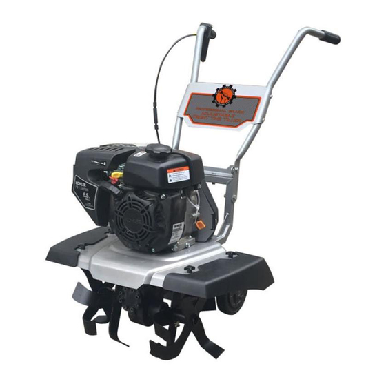
- Page 1 14”-22” ADJUSTABLE FRONT TINE TILLER MODEL # 107555 Operation Manual This safety alert symbol identifies important safety messages in this manual. Failure to follow this important safety information may result in serious injury or death. Part 108749 Rev B...
- Page 2 For Service or Questions Call 1-877-487-8275 720-287-5182 www.dirtyhandtools.com Dirty Hand Tools® is a brand of 1100 W 120th Ave, Suite 600 Westminster, CO 80234 • 720-287-5182...
-
Page 3: Table Of Contents
Table of Contents Important Safety Information Intended Use ................4 Personal Protective Equipment ..........4 General Safety ................5 Safety Decals ................6 Unpacking and Assembly Instructions Unpacking ...................7 Overview of Components .............8 Tine Assembly ................9 Handlebar Assembly ..............10 Installing the Wheels ..............11 Safety Shield Assembly ...............12 Operating Precautions ..............13 Operating Instructions Preparation for Operation ............14... -
Page 4: Important Safety Information
Important Safety Information WARNING WARNING: Read and thoroughly understand all instructions and safety information before assembling or operating this tiller. Failure to do so may cause serious injury or death. Do not allow anyone to operate this tiller who has not read this manual. As with all power equipment, a tiller can be dangerous if assembled or used improperly. -
Page 5: General Safety
Important Safety Information General Safety Failure to follow warnings, cautions, assembly and operation instructions in the Operation Manual may result in serious injury or death. DANGER READ THE OPERATION MANUAL BEFORE OPERATION. • Do not permit children to operate this equipment at any time. •... -
Page 6: Safety Decals
Important Safety Information Safety Decals Safety labels on the tiller are to remind you of important information while you are operating the unit. Make sure all safety warning decals are attached and in readable condition. Replace missing or defaced decals. Contact Dirty Hand Tools at 1-877-487-8275 for replacement decals. -
Page 7: Unpacking And Assembly Instructions
Unpacking and Assembly Your tiller will require some assembly. The following instructions will help you unpack your tiller, assemble and adjust the depth regulator lever, cable tension and handlebar height. You will need a wrench, small adjustable crescent wrench and a starbit driver to complete the assembly. -
Page 8: Overview Of Components
Overview of Components CLUTCH LEVER THROTTLE / CHOKE CONTROL HANDLEBAR ASSEMBLY FUEL FILL RECOIL MUFFLER STARTER CLEANER COVER OIL FILL / DIPSTICK SAFETY SHIELD (TINE GUARD) WHEEL ASSEMBLY INNER TINE OUTER TINE ASSEMBLY ASSEMBLY... -
Page 9: Tine Assembly
Tine Assembly Mounting the Tine Blades 1. Mount the 4 tines assemblies. Note that all 4 blades are different. The sharp edge of the blade should face forward, in the operational ASSEMBLED TINES SECURED direction. Make sure the clevis pin is securely fastened with a lynch pin. WITH LYNCH PINS Slide the tines onto the tiller’s axle. -
Page 10: Handlebar Assembly
Handlebar Assembly Mounting the Handlebars NOTE: The left and right handlebars are different. Each has two holes drilled in the bottom of the handlebar tube and two more drilled in the middle. 1. Install the upper handlebar bracket to the square tubing of the frame using two M8x40mm bolts and nyloc nuts and two 13mm wrenches in the configuration shown in Figure 2. -
Page 11: Installing The Wheels
Installing the Wheels 1. Locate the wheels and remove the hub caps. 2. Place the wheels on the axles, making sure that the hub cap side is facing outwards. 3. Install the wheels using the provided hardware noted in Figure 3. 4. -
Page 12: Safety Shield Assembly
Safety Shield Assembly NOTE: Tine guards must be in place for tilling in the 18” and 22” tilling width. 1. Locate the plastic winged nuts and guards. 2. Install the guards on their respective sides, using the plastic winged nuts (see Figure 4), ensuring that they are safely and securely fastened to the machine. -
Page 13: Operating Precautions
Operating Precautions CAUTION READ, UNDERSTAND AND FOLLOW ALL OF THE PRECAUTIONS BELOW. Always perform the pre-start checklist before starting the engine. • Never operate the tiller without safety shields in place. • Keep hands, feet, and clothing away from rotating parts. Keep clear of tiller tines at all times. -
Page 14: Operating Instructions
Operating Instructions Preparation for Operation FUEL FILL AIR FILTER COVER WARNING THIS UNIT WAS SHIPPED WITHOUT OIL IN THE ENGINE. Check the oil level before each operation. Fill Engine with Oil 1. Add oil according to engine manual. Do not overfill. Use SAE30 engine oil. -
Page 15: Start-Up
Operating Instructions WARNING NEVER FILL THE FUEL TANK ON A HOT ENGINE CHOKE/THROTTLE Start-Up LEVER 1. Turn the Engine ON/OFF switch to ON (see Figure 7). 2. Slide the fuel shutoff lever to the right (open) position Figure 8 Cold Starts 1. -
Page 16: Tilling
Operating Instructions WARNING Read Operation Manual before using this equipment! Practice operating the controls and using the tiller with tines out of ground before beginning to till. Tilling 1. Start the engine. 2. Move the throttle control to fast. 3. Place the tiller in forward by pulling up on the forward clutch lever - this will engage the tines. -
Page 17: Maintenance
Maintenance • Keep tiller, safety shields and covers, attachments, and accessories in safe working condition. • Check clevis pins, engine mounting bolts, and other bolts at frequent intervals for proper tightness to be sure the equipment is in safe working condition. •... -
Page 18: Storage
Storage WARNING DO NOT STORE THE TILLER IN UNVENTILATED AREA where fuel fumes may reach flame, sparks, pilot lights or other ignition source. Drain fuel outdoors away from any ignition sources. Use only approved fuel containers. Never store equipment with gasoline in the tank inside of a closed building where fumes may reach an open flame or spark. -
Page 19: Troubleshooting
Troubleshooting PROBLEM SOLUTION Engine will not start • Add gas to gas tank. • Connect spark plug wire to spark plug • Throttle must be positioned at choke for a cold start Engine runs rough, floods during operation • Clean or replace air cleaner Engine is hard to start •... -
Page 20: Warranty & Specifications
Record the information below for future reference. Model No. Serial No. Date of Purchase Place of Purchase Specifications SKU/Part No. 107555 Description 14 - 22 Inch Front Tine Tiller Engine 10.7 ft/lbs Gross Torque (6.5HP 196cc) Kohler Engine*, EPA/CARB Approved Engine Oil Capacity** 0.6 quarts...
Need help?
Do you have a question about the 107555 and is the answer not in the manual?
Questions and answers
What is the belt size?