Table of Contents
Advertisement
Advertisement
Table of Contents

Related Manuals for Jamar RAC Plus I


Summary of Contents for Jamar RAC Plus I
- Page 1 RAC Plus I User’s Manual...
- Page 2 RAC Plus I User’s Manual WARNING Use of the RAC Plus I while driving could cause an accident, resulting in serious injury or death. As with any in-vehicle instrumentation, the information provided by the RAC Plus I should be observed as part of the normal operation of the vehicle. Changes to the RAC Plus I should only be done in a safe manner.
- Page 3 JAMAR Technologies immediately and discontinue use of the unit until we have verified its operation. If you have any questions about the use of the RAC Plus I, please call the following number: 1-215-361-2244 Monday —...
-
Page 4: Table Of Contents
RAC Plus I User’s Manual Table of Contents Technical Support ............iii Quick Start Guide .............v Introduction to the RAC Plus I ............1-1 What is the RAC Plus I? ............1-2 How Does It Work? ............1-3 Installation ............2-1 Before You Begin ............ -
Page 5: Quick Start Guide
Quick Start Guide The RAC Plus I DMI will allow you to accurately measure distance quickly and easily. However, before you can do this a few basic steps must be taken to ensure that you get the optimum performance from your instrument. - Page 6 RAC Plus I User’s Manual...
-
Page 7: Introduction To The Rac Plus I
Chapter 1 — Introduction to the RAC Plus I Chapter 1 Introduction to the RAC Plus I... -
Page 8: What Is The Rac Plus I
RAC Plus I User’s Manual What is the RAC Plus I? The JAMAR Technologies Road Analysis Computer (RAC) Plus I is an accurate, easy-to-use distance measuring instrument (DMI) that uses state- of-the-art microprocessor technology. It has been designed with features to provide you with a versatile and functional instrument that can be learned in a very short time. -
Page 9: How Does It Work
Chapter 1 — Introduction to the RAC Plus I How does it work? The RAC Plus I is installed in your car along with a distance sensor. Distance sensors do the behind-the-scenes work of the RAC Plus distance measuring instruments. Connected between your vehicle and the RAC Plus head unit, these sensors read and modify the data coming from your vehicle and send a signal to the RAC telling it when to count distance. - Page 10 RAC Plus I User’s Manual...
-
Page 11: Installation
Chapter 2 — Installation Chapter 2 Installation... -
Page 12: Before You Begin
RAC Plus I User’s Manual Before You Begin The JAMAR RAC Plus I distance measuring instruments are very reliable. However, there can be some external variables that could affect proper op- eration and the ability to accurately measure distance traveled. By observing a few simple precautions you will be able to eliminate potential problems. -
Page 13: Installing The Obd Distance Sensor
Chapter 2 — Installation Installing the OBD Distance Sensor These instructions are for installing a RAC Plus I with an OBD Distance Sensor. If you are installing a different type of sensor, skip this section. The AutoLink allows connection between the On-Board Diagnostics (OBD) connector in your vehicle and the RAC Plus Distance Measuring Instrument. - Page 14 RAC Plus I User’s Manual IMPORTANT: Note that the supplied grey telephone-style cable is the ONLY cable that should be used. DO NOT use any other cables that may have been provided with your RAC as you may damage your RAC or the AutoLink.
- Page 15 Chapter 2 — Installation • After using your RAC, you should turn off the RAC while your vehicle is not being used. Power consumption of the RAC display, although minimal, may drain your battery if the vehicle is idle for an extended time with the RAC connected and turned on.
-
Page 16: Installing The Modular Distance Sensor
RAC Plus I User’s Manual Installing the Modular Distance Sensor Note: These instructions are for installing a RAC Plus I with a Modular Distance Sensor. If you are installing a different sensor, skip this section. 1. Find a location under the vehicle dashboard that will allow fairly easy access to the MDS. - Page 17 Chapter 2 — Installation Use the cable ties provided while routing the cable to the location for getting the speed signal that you previously identified. Attach the red wire of the VSS cable to the high-speed signal wire of the vehicle’s speed sensor using the tap splice connectors provided.
- Page 18 RAC Plus I User’s Manual is switched off with the ignition key. We also recommend the circuit should have as few devices as possible to avoid voltage fluctuations from Turn Signals, Brake Lights, etc. Plug the power cable Fig. 2.6 –Power Plug-in into the hole labeled Power on the MDS, as shown in Figure 2.6.
- Page 19 Chapter 2 — Installation Filter Toggle As a default, the Filter toggle should be set to ‘Filter Off’. However, on some vehicles there is ‘noise’ on the speed sensor line that causes the RAC to count Fig. 2.8 – up while the vehicle is not moving. The filter toggle Filter Toggle should be flipped to ‘Filter On’...
-
Page 20: Installing The Magnetic Distance Sensor
RAC Plus I User’s Manual Installing the Magnetic Distance Sensor Note: These instructions are for installing a RAC Plus I with a Magnetic Distance Sensor. If you are installing a different sensor, skip this section. For the installation you will need the Magnetic Sensor Kit shown below. - Page 21 Chapter 2 — Installation Once you have finished the following steps, your installation should look similar to Figure 2-12 below. Instrument black wire to battery ground and sensor black wire. Figure 2-12 Instrument yellow wire to battery +12 VDC and sensor white wire. Instrument green wire to sensor red wire.
- Page 22 RAC Plus I User’s Manual To install the magnets (part A in South figure 1) on the drive shaft, use North North the Epoxy (B). Spare magnets are provided in the Hardware Kit (E) South should they be needed. Test magnet should alternately attract and repel.
- Page 23 Chapter 2 — Installation Step 2 – Attaching the Magnetic Sensor The Magnetic Sensor (F) is mounted Sensor assembly directly over the magnets as shown in To Figure 8 must not be mounted more than 45 from figure 3. When the wheel or drive shaft perpendicular begins turning, a speed impulse is sent to the DMI every time a magnet passes...
- Page 24 RAC Plus I User’s Manual with a water tight plug on the end. There is also a heaver wire Extension Cable (G) 10 feet in length. This will allow you to use up to 15 feet of wire for the installation from the magnetic sensor location to the terminal block.
-
Page 25: Installing The Rac Instrument
Chapter 2 — Installation Installing the RAC Instrument The compact case design of the RAC Plus allows mounting of it in a num- ber of convenient locations. Popular locations include on the front of the dashboard, above or below the dashboard, or on the windshield using the optional windshield mounting bracket. - Page 26 RAC Plus I User’s Manual Once you have mounted your RAC and connected it to the distance sensor, proceed to the calibration instructions in the following chapter. 2-16...
-
Page 27: Calibration
Chapter 3 — Calibration Chapter 3 Calibration... -
Page 28: Automatic Calibration Procedure
RAC Plus I User’s Manual Automatic Calibration Procedure In order to accurately measure distance, your RAC Plus must know the exact distance that the vehicle will travel based on pulses from the vehicle's speed sensor. The calibration number is the automatic calculation that represents the number of pulses received over a set distance. - Page 29 Chapter 3 — Calibration Step 2 Press the Menu key, the # 1 key and Enter. At this point, the unit of mea- surement will automatically change to feet. You can then select the vehicle number that this calibration will be Fig.
- Page 30 RAC Plus I User’s Manual Step 7 Press Enter and the unit of measurement will return to your desired unit of feet, mile or meter. Press Enter again to exit the menu function and return to normal operation. Your calibration number for the vehicle selected is now stored in the RAC's nonvolatile (permanent) memory.
-
Page 31: If Your Rac Fails To Calibrate
Chapter 3 — Calibration If Your RAC Fails to Calibrate If your RAC fails to count during calibration, perform the following op- erational checks: Step 1 Locate the Sensor Test button on the front upper right of the MDS, shown in Figure 3.5. - Page 32 RAC Plus I User’s Manual Step 2 The Tap Test will determine if the dis- tance pulses being sent from the MDS are getting to, and being processed by, the RAC. The Tap Test is performed using the rotary switch shown in figure 3.6.
-
Page 33: Manual Calibration Procedure
Chapter 3 — Calibration Manual Calibration Procedure It is very common to share one RAC on a plug-in basis between a number of different vehicles that have been equipped to accept the instrument. Installing additional vehicle kits on other vehicles is an inexpensive and cost effective means to greatly expand your measuring capabilities. - Page 34 RAC Plus I User’s Manual Step 3 Press the Enter key and the current cali- bration number for the vehicle selected will be displayed. Press the Clear key (CLR) to clear the current number. Fig. 3.9 Calibration Number Cleared Step 4...
-
Page 35: Key Functions & Operating Procedures
Chapter 4 — Key Functions & Operating Procedures Chapter 4 Key Functions & Operating Procedures... -
Page 36: Rac Plus I Key Functions
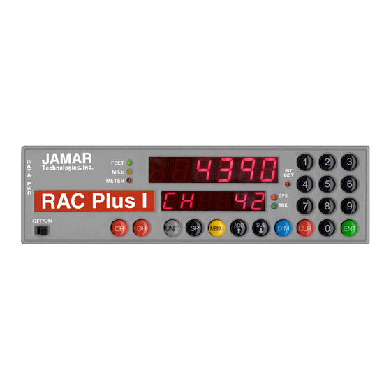
RAC Plus I User’s Manual RAC Plus I Key Functions Fig. 4.1 — RAC Plus Key Layout Your RAC Plus series DMI has been designed for simple operation, using large individual keys which provide a click and tone feedback. The two 6-digit high-intensity LED display windows (exclusive to the RAC Plus series) allow flexibility in displaying data to you. - Page 37 Chapter 4 — Key Functions & Operating Procedures Display Hold will stop the display from updating while the RAC will continue to accumulate distance internally. When in Display Hold, DH will be displayed in D-2. If speed is also Display being displayed, it will continue as DH does not freeze the Hold speed display.
- Page 38 RAC Plus I User’s Manual The Sub key instructs the RAC to count down. When in this mode, the LED indicator for the active unit of measurement will flash to indicate that you are subtracting distance. Should Subtract you count down to zero (0), the RAC will provide a tone and automatically begin counting up.
-
Page 39: Rac Plus I Menu Functions
Chapter 4 — Key Functions & Operating Procedures RAC Plus I Menu Functions The Menu key of the RAC allows you to select from a variety of functions. After pressing the Menu button, the Add and Sub keys can be used to scroll through the options, which are displayed in D-2. - Page 40 RAC Plus I User’s Manual Menu 4 - Clock Set The RAC Plus will compute & display time as either elapsed time from when the instrument was powered up, or real time if the timer has been set. The timer starts automatically at zero when the RAC is powered-up. Time is displayed in D-1 as hh.mm.ss.
- Page 41 Chapter 4 — Key Functions & Operating Procedures Note: To view the Clock/Timer while in the normal measuring mode (not as a Menu function), press the #1 key. D-1 will then display the clock/timer in hh.mm.ss format. Press the #1 key again to toggle back to distance. This function does not interrupt the distance count.
- Page 42 RAC Plus I User’s Manual Step 2 Using the numeric keys, enter the interval distance that you want the DPO signal generated, based on your selected unit of measurement (feet, mile, meter). Fig. 4.9 — DPO Distance Entered Step 3...
- Page 43 Chapter 4 — Key Functions & Operating Procedures To turn off the DPO signal: Step 1 Press the Menu key, the #5 key then Enter. The current DPO interval dis- tance is then displayed in D-1. Fig. 4.13 — Current DPO Distance Step 2 Press the CLR (clear) key and the DPO distance is removed.
-
Page 44: Rac Plus I Additional Features
RAC Plus I User’s Manual RAC Plus I Additional Features Interval Distance This feature allows you to determine distance between points of interest, such as telephone poles, signs, pavement markings, etc. You can activate Interval Distance at any time as long as you are in the normal measuring mode and not using the menu functions. -
Page 45: Troubleshooting
Chapter 5 — Troubleshooting Chapter 5 Troubleshooting... -
Page 46: Frequently Asked Questions
RAC Plus I User’s Manual Frequently Asked Questions Q. My RAC will not count. What’s wrong? A. In most cases, when a RAC Plus won’t count, it is not the unit itself that has the problem. It is usually a problem with the interface sensor or wiring. - Page 47 2. Your ground wire may not be connected properly. Double check its connections. 3. Your Modular Distance Sensor may not be working correctly. Contact JAMAR using the information on page iii for information on getting replacement parts.
- Page 48 RAC Plus I User’s Manual Q. My RAC will not turn on. What’s wrong? A. There are two possible causes for this. 1. You may have a loose connection. Double check all connections at the MDS and RAC to make sure they are tight and at the correct locations.
-
Page 49: Appendix
Appendix Appendix... -
Page 50: Rac Plus I Specifications
— 50+ years retention. Circuitry: Solid state, surface mount, modular, EEPROM, micro-computer. Case: ABS plastic. Dimensions: 7.8"W x 2.3"H x 1.2" D Weight: 6.5 oz. Operating Temperature: 0°C to 75°C Warranty: 5-year instrument warranty. Example: JAMAR Technologies RAC Plus I... -
Page 51: Power Connection Wiring
Appendix Power Connection Wiring Pin 1 (Yellow) +12 VDC Pin 2 (Green) Sensor Input Pin 3 (Red) Pin 4 (Black) Signal Ground 4 3 2 1... -
Page 52: Glossary
Memory. It contains the permanent memory of the RAC. Page A-2. ENT (Enter) — green button on the RAC, it accepts any number keyed into the display. Page 4-4. LED — stands for light emitting diode, the display used with the JAMAR RAC Plus series. Page A-2. - Page 53 P-Dis (Pre-Distance) — menu function of the RAC, it allows you to enter a known distance into the RAC. Page 4-5. RAC — Road Analysis Computer. Brand name for JAMAR’s distance measuring instruments. SP (Speed) — black button on the RAC, it allows you to show your speed.
-
Page 54: Vehicle Calibration Record
RAC Plus I User’s Manual Vehicle Calibration Record Date: Date: _________________________ _________________________ Veh. No: Veh. No: ______________________ ______________________ Cal. Factor: _________________ Cal. Factor: _________________ Veh. Odometer: Veh. Odometer: _______________ _______________ User Initials: ________________ User Initials: ________________ Date: Date: _________________________ _________________________ Veh. - Page 56 RAC Plus I User’s Manual...
Need help?
Do you have a question about the RAC Plus I and is the answer not in the manual?
Questions and answers