Table of Contents
Advertisement
Quick Links
PRODUCT OVERVIEW
This document covers the installation, operation and maintenance
of Type 200 presented in the "Level Controls and Accessories",
Product Specification.
GENERAL INFORMATION
The instructions given herein cover generally the operation
and maintenance of subject equipment. Should any
questions arise which may not be answered specifically
by these instructions, they should be referred to Warren
Controls Inc. for further detailed information and technical
assistance. This manual cannot possibly cover every situation
connected with the operation, adjustment, inspection, test,
overhaul and maintenance of the equipment furnished.
Every effort is made to prepare the text of this manual so
that engineering and design data is transformed into the
most easily understood wording. Warren Controls Inc., in
furnishing this equipment and this manual, must presume
that the operation and maintenance personnel assigned
thereto have sufficient technical knowledge and experience
INSTALLATION, OPERATION
& MAINTENANCE INSTRUCTIONS
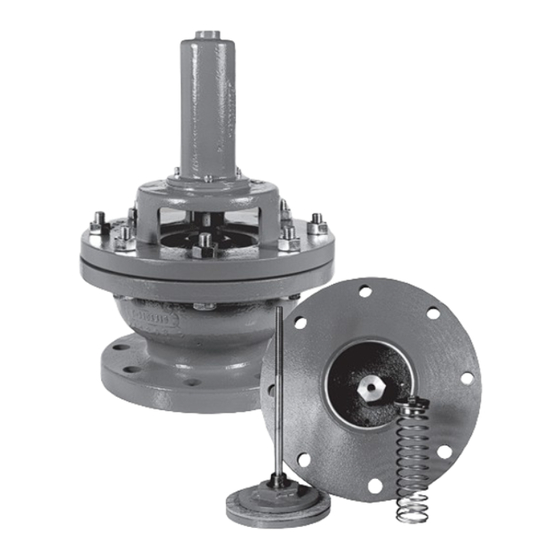
VACUUM BREAKER
TABLE OF CONTENTS
Overview ........................................................ COVER
General Information ................................... COVER
Installation ................................................................ 4
Operation .................................................................. 4
Maintenance ............................................................ 4
Seat Inspection & Cleaning Procedures ......... 5
Opening Force Test & Adjustment
Procedures ................................................................ 6
Overhaul .................................................................... 6
Vacuum Breaker ...................................................... 7
Parts Kits ........................................................... 12-13
Construction Drawing & Dimensions............14
to apply sound safety and operational practices which
may not be covered herein. In applications where Warren
Controls Inc. furnished equipment is to be integrated with
a process or other machinery, these instructions should be
thoroughly reviewed to determine the proper integration of
the equipment into the overall plant operational procedures.
Warren Controls does not assume responsibility for
the selection, use, or maintenance of any product.
Responsibility for proper selection, use, and maintenance
of any Warren Controls product remains solely with the
purchaser and end-user
TYPE 200
Advertisement
Table of Contents

Summary of Contents for Warren Controls 200
-
Page 1: Table Of Contents
Construction Drawing & Dimensions....14 200_IOM_RevC_0618 PRODUCT OVERVIEW This document covers the installation, operation and maintenance of Type 200 presented in the “Level Controls and Accessories”, Product Specification. GENERAL INFORMATION The instructions given herein cover generally the operation to apply sound safety and operational practices which and maintenance of subject equipment. - Page 2 WARNING! CHECK VACUUM BREAKER FOR ANY DAMAGE DUE TO IMPROPER STORAGE OR TRANSPORTATION. IMMEDIATELY NOTIFY YOUR SALES ORGANIZATION OF ANY DAMAGED GOODS UPON RECEIPT. DO NOT ATTEMPT TO MOVE OR DISTURB THE VACUUM BREAKER FURTHER SO PHOTOS MAY BE TAKEN. IF THE SHIPPING CONTAINER IS NOTICEABLY DAMAGED REFUSE RECEIPT, AS THE SHIPPING COMPANY SHOULD BE HELD LIABLE...
- Page 3 Trap relieves the overflow through its internal single seated main stage valve. Falling liquid levels and condensing steam can cause a vacuum that can damage the tank. The [D] Type 200 Vacuum Breaker opens to admit outside air to relieve the vacuum in the tank.
-
Page 4: Installation
The atmospheric pressure then acts on the discholder to overcome the force of the vacuum breaker’s spring. The seat and disc separate admitting outside air. The Type 200 Vacuum Breaker opens gradually to admit outside air to relieve the vacuum in the tank/ pipeline. -
Page 5: Procedures
18) Install bolts through holes in adapter body and valve body. Install nuts on bolts. Tighten nuts and bolts in increments in an alternating pattern. 19) Complete steps 4 thru 10 of Opening Force Adjustment Procedure. Level Controls - IOM 200 VACUUM BREAKER 200__IOM_RevC_0618... -
Page 6: Overhaul
OPENING FORCE TEST PROCEDURE 1) Remove line or tank pressure and isolate vacuum breaker. (It is recommended that the vacuum breaker be removed from the piping or tank for the test procedure) 2) Remove capscrews from spring chamber. 3) Remove spring chamber from valve body. 4) Apply water to cover top of disc. -
Page 7: Information Present On
This information is important for identifying the vacuum breaker, installing it correctly, and obtaining parts. An example of the current factory serial number label used on Type 200 vacuum breakers is shown here. The accompanying table identifies the information present and where to find it on the vacuum breaker. There may also be other casting numbers and foundry marks present that do not provide useful information. -
Page 8: Type 200 Vacuum Breaker Specifications
TYPE 200 VACUUM BREAKER SPECIFICATIONS Serial number label located here WITH STANDARD TRIM (INTEGRAL SEAT, NON-ASBESTOS Sales order (serial) DISC AND STEEL DISCHOLDER) number stamped here Body Material Size End Connection Part Number 2* 125FLG 020009EXX000 IRON 2* 020009IXX000 125FLG... - Page 9 125FLG 020017EXX004 125FLG 020019EXX009 125FLG 020020EXX004 150FLG 020009GXX004 STEEL 150FLG 020013GXX004 150FLG 020015GXX004 150FLG 020017GXX004 150FLG 020019GXX004 150FLG 020020GXX004 300FLG 020009HXX004 STEEL 300FLG 020013HXX004 300FLG 020015HXX004 300FLG 020017HXX004 300FLG 020019HXX004 300FLG 020020HXX004 Level Controls - IOM 200 VACUUM BREAKER 200__IOM_RevC_0618...
- Page 10 3427 6093 9520 14280 STANDARD OPTION The Type 200 cannot be set to open at a particular vacuum. The vacuum values presented in the table are for reference only. WEIGHTS: VALVE SIZE (IN) Weight (lb) For dimensions see drawing 0200032510.
-
Page 11: Type 200 Vacuum Breaker Parts/Overhaul
Two different parts kits are available. An Inspection kit is available to allow a vacuum breaker to be opened to inspect its internal parts. A rebuild kit is available to allow a vacuum breaker to be overhauled. Please provide serial number to get the correct kit part numbers. Level Controls - IOM 200 VACUUM BREAKER 200__IOM_RevC_0618... -
Page 12: Parts Kits
TYPE 200 VACUUM BREAKER PARTS KITS The inspection kit allows a vacuum breaker to be opened so the condition of its internal parts may be inspected. The rebuild kits allow a vacuum breaker to be overhauled. (Provide vacuum breaker serial number to get kit part numbers) -
Page 13: Parts Kits
SIZE 10 & 12 INCH EFFECTIVE DATE: 9/26/2008 SEE DWG 0200032510 ITEM DESCRIPTION ITEM DESCRIPTION JAMNUT DISC RETAINER SPRING BUTTON GASKET OUTER SPRING DISC HOLDER STEM DISC STEM GUIDE SEAT RING CONNECTING PIN INNER SPRING Level Controls - IOM 200 VACUUM BREAKER 200__IOM_RevC_0618... - Page 14 DRAWING 0200032510 2600 Emrick Blvd • Bethlehem, PA 18020 • USA • 800-922-0085 • www.warrencontrols.com...
- Page 15 NOTES Level Controls - IOM 200 VACUUM BREAKER 200__IOM_RevC_0618...
-
Page 16: 200_Iom_Revc_0618
200_IOM_RevC_0618 2600 EMRICK BLVD • BETHLEHEM, PA 18020 • USA •800-922-0085 • WWW.WARRENCONTROLS.COM DEPENDABLE, RUGGED, PRECISION CONTROL VALVES AND ACCESSORIES...
Need help?
Do you have a question about the 200 and is the answer not in the manual?
Questions and answers