Table of Contents
Advertisement
Quick Links
QUICK START GUIDE
This guide covers the following Bridge Technologies devices: VB120, VB20, VB220
and VB330. Optional interface modules, like demodulators, do not require initial
set-up. For further information download the User Manual and refer to section
4.1. The serial number can be found on the unit.
Note: that individual probes in a chassis must be configured separately.
These modules have a USB port.
Manuals can be downloaded from the end-user log-in area of Bridge
Technologies' web site
www.bridgetech.tv - click Login
user name: customer
password: xmas4u
Health and safety
Read the safety chapter of the User's Manual, to avoid potential hazard.
Technical support
Contact your Bridge Technologies Partner/Reseller or refer to your support
agreement.
Warranty/Software Upgrades/Training/General enquiries
Contact your Bridge Technologies Partner/Reseller.
Unpack Equipment
Check that there are no obvious damages to equipment due to transport. If
equipment appears to be damaged, please contact your Bridge Technologies
reseller for support.
In addition to the Bridge Technologies hardware itself, the shipment should
include a power cable (two for enhanced chassis) and a USB cable.
Install Equipment and Power Up
Equipment designed for rack installation should be securely connected to the
rack using rack screws suitable for the rack type.
When the equipment is installed, it can be powered up by connecting it to a
power outlet using the power cable(s). Bridge Technologies devices for AC mains
can operate in the range 100–240VAC. Refer to the User's Manual for a
description of DC power connection.
Initial Configuration
There are 2 alternative ways of performing an initial configuration:
1. Preconfigured IP address of the probe management port (Go to 1.)
2. Via serial console emulated over USB (Go to 2.)
Quick Start Guide Monitoring Probe v1 ©BRIDGE Technologies Co AS
1
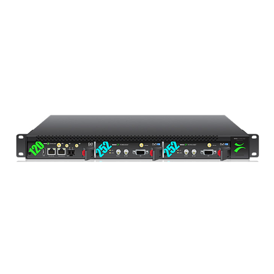
In the box: Monitoring Probe + Power cord & supply USBA-A Cable
Note that there should be sufficient room for air to freely flow around
the unit, ensuring proper cooling. Also note the direction of air flow for
your chassis type prior to installation (refer to the User's Manual).
Advertisement
Table of Contents

Related Manuals for BridgeTech VB120

Summary of Contents for BridgeTech VB120
-
Page 1: Technical Support
QUICK START GUIDE This guide covers the following Bridge Technologies devices: VB120, VB20, VB220 and VB330. Optional interface modules, like demodulators, do not require initial set-up. For further information download the User Manual and refer to section 4.1. The serial number can be found on the unit. - Page 2 1. Configuration Using the Pre-Set IP-Address 2. Connecting to the serial console over USB The factory settings for the wired management interface are: For the initial set-up, do the following: Management (eth1) IP address: 10.0.20.101 1. Install a driver for the USB communication Management (eth1) subnet mask: 255.255.0.0 (if not already supported by the operating system) 2.
- Page 3 Start a terminal program. A simple text based menu system should now be displayed. To change a setting, press the appropriate character from the left-most column, enter the new value - Windows XP users can use Hyperterm and confirm by pressing ENTER. If DHCP is enabled, you can find the currently - Linux users can use Minicom assigned IP address by selecting the ethStatusDoc option.
- Page 4 Verifying Correct Initial Setup Check Licensing Once the probe management network interface has been configured, all further Check that the device licensing is correct in the About - License view. configuration takes place using a web browser over HTTP. Set Network Parameters Launch a web browser application on the management PC.
Need help?
Do you have a question about the VB120 and is the answer not in the manual?
Questions and answers