
Related Manuals for FeelTech FY6600 Series


Summary of Contents for FeelTech FY6600 Series
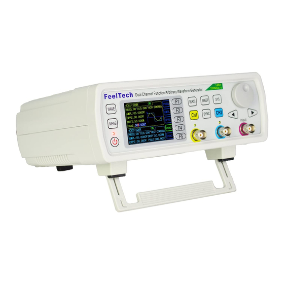
- Page 1 FeelTech FY6600 Series Fully Numerical Control Dual Channel Function/Arbitrary Waveform Generator User’s Manual Rev2.9 August,2017...
-
Page 3: Guaranty And Declaration
FeelTech Guaranty and Declaration Copyright © 2017 FeelTech Technology Co. Ltd. All Rights Reserved. Declaration FeelTech ● reserves the right to modify or change parts of or all the specifications and pricing policies at company’s sole decision. ● Information in this publication replaces all previously corresponding material. -
Page 4: Table Of Contents
Enable Sweep Function .................... 35 System Configuration and Auxiliary Functions ..........36 Save and Load ......................37 Configuration ......................38 Uplink ......................... 39 Synchronization ......................40 Troubleshooting ....................41 Technical Specification ..................42 Appendix ......................46 FY6600 Series User’s Manual... -
Page 5: Product Introduction
“FY6600-60M” indicates the Sine wave maximum output frequency is up to 60MHz. FY6600 series Dual-channel Function / Arbitrary waveform generator is a set of Function Signal Generator, Arbitrary Waveform Generator, Pulse Generator, Analog / Digital modulator, VCO, Sweep, Counters and Frequency Meter and other functions in a high Performance, cost-effective, multi-function signal generator. - Page 6 Channel SYNC Function: Support waveform copy and state copy between channels. Support two or more signal generators connected to achieve multi-channel output, the maximum support 16-channel synchronous output, the phase between each channel can be adjusted. FY6600 Series User’s Manual...
- Page 7 Adopt ABS plastic shell with table type design. Use 100-240V (AC) wide range voltage power supply. Can choose our FYA2000S series or FPA1000 series power amplifier to output 20W~100W signal in DC-10MHz width without any distortion. FY6600 Series User’s Manual...
-
Page 8: Quick Start
FeelTech Quick Start General Inspection Please follow the items below when you receive a new FY6600 series Function/Arbitrary Waveform Generator. 1. Inspect the shipping container for damage Keep the damaged shipping container or cushioning material until the contents of the shipment have been checked for completeness and the instrument has passed both electrical and mechanical tests. -
Page 9: Front Panel Overview
— Can save 20 sets waveform parameters including frequency, amplitude, offset, phase and so on. — System Language has English and Chinese for user’s option. — Buzzer can be turned on/off in this manu. — Set multimachine uplink. FY6600 Series User’s Manual... - Page 10 Press it to turn on CH2 output with current configuration. The indicator will illuminate. — Press it again to turn off CH2 output and the indicator will extinguish. Synchronization function button. Can set synchronization of CH1 and CH2 (Frequency, Amplitude, Offset and so on). FY6600 Series User’s Manual...
- Page 11 CH2 connector, output impedance is 50Ω. output When CH2 channel activates (indicator illuminates), CH2 outputs connector signal with parameters set. AC coupling BNC connector, input impedance 100Ω. For inputting signal of meter or measuring counter. terminal FY6600 Series User’s Manual...
-
Page 12: Back Panel Overview
Port C is same with frequency of CH2. Frequency of Port D is same with Port C but with reverse phase (180°). 4. USB Device interface It’s for communication with PC (This is a USB-TTL serial port and driver is needed). Can programming by host computer. 5. Power input socket(voltage range AC100V-AC240V). FY6600 Series User’s Manual... - Page 13 FeelTech Warning To avoid instrument damage, voltage of signal input from EXT.IN CANNOT exceed ±20Vac+dc.Voltage of signal input from Trig/FSK/ASK/PSK IN CANNOT exceed DC5V. Note To ensure the normal work, please use 100-240V AC power supply. FY6600 Series User’s Manual...
-
Page 14: Power On And Inspection
If the generator cannot work normally, please check the Chapter “Troubleshooting” for solution. Set the System Language FY6600 series Function/Arbitrary Waveform Generator supports Chinese and English system languages. You can press SYS→CONF to switch the system language. -
Page 15: User Interface
Display On/Off status of current channel. It can be switched by Press CH1 or CH2. Waveform Display diagram of current waveform(Including Arbitrary). Yellow indicates CH1 and blue indicates CH2. Manu Bar Display current operable options . FY6600 Series User’s Manual... - Page 16 Display parameters of the channel unselected including frequency, amplitude, offset, phase, duty cycle and output status. These Parameters cannot be changed directly in this interface. If you need to change them, Please switch the channel to be selected. FY6600 Series User’s Manual...
-
Page 17: Appearance And Dimensions
FeelTech Appearance and Dimensions FY6600 Series User’s Manual... -
Page 18: Front Panel Operations
Front Panel Operations Waveform Output FY6600 series can output waveforms (Sine, Square, Triangle/Ramp, Pulse and Noise etc.) from one of the channels separately or from the two channels at the same time. At start-up, the dual channels are configured to output a sine waveform with 10kHz frequency and 5Vpp amplitude by default. -
Page 19: Select Waveform
√ Phase √ √ √ √ √ Duty Cycle √ Note: Arbitrary waveforms can be edited and downloaded from PC software provided by FeelTech. The relevant software and driver can be downloaded from our website: www.feeltech.net FY6600 Series User’s Manual... -
Page 20: Set Frequency
ADJ Knob to set the value. Press Arrows button to move the cursor and rotate ADJ Knob to set the value. Under setting frequency status, press ADJ Knob to change frequency units among MHz, KHz, Hz, mHz, μHz. FY6600 Series User’s Manual... -
Page 21: Set Amplitude
According to the figure above, the conversion relation between Vpp and Vrms fulfills the following equation: Vpp = 2 2 Vrms For example, if the current amplitude is 5Vpp, For sine waveform, the converted value is 1.768Vrms. FY6600 Series User’s Manual... -
Page 22: Set Offset
ADJ Knob to set the value. The offset accuracy is 1mV. i.e. 0.001V. When frequency output is lower than 20MHz, the offset can be adjusted during -10V~+10V. When frequency output is higher than 20MHz, the offset can be adjusted during -2.5V~+2.5V. FY6600 Series User’s Manual... -
Page 23: Set Duty Cycle (Square)& Set Pulse Wave Pulse Width (Adj-Pulse)
(Note: Do not set the length of the positive pulse width greater than or equal to the cycle time of the output waveform). FY6600 Series User’s Manual... -
Page 24: Set Phase
Then press PHAS button to highlight phase value. Then use Arrows button and ADJ Knob to set the value. Press Arrows button to move the cursor and rotate ADJ Knob to set the value. FY6600 Series User’s Manual... -
Page 25: Enable Output
CH2, then press CH2 to switch between output ON/OFF. 4) Generator is in other working status or current channel selected is not CH2, then press CH2 to make CH2 as channel selected and press CH2 again to switch between output ON/OFF. FY6600 Series User’s Manual... -
Page 26: Example:output Sine Waveform
Press CH1 button to turn CH1 output on. The [CH1] connector outputs the configured waveform. 8. Observe the output waveform Connect the [CH1] connector to the oscilloscope with BNC cable. The waveform is as shown below. FY6600 Series User’s Manual... - Page 27 FeelTech FY6600 Series User’s Manual...
-
Page 28: Burst
Press the [WAVE] button to change the current burst output signal waveform. Press the [FREQ] button to change the current burst output signal frequency. Press the [AMPL] button to change the current burst output signal amplitude. FY6600 Series User’s Manual... -
Page 29: Modulation Function
Source Internal (CH2), External (FSK IN Port), Manual Modulating Waveform Square with 50% duty cycle. Key Frequency 1μHz~10MHz Source Internal (CH2), External (PSK IN Port), Manual Modulating Waveform Square with 50% duty cycle. Key Frequency 1μHz~10MHz FY6600 Series User’s Manual... -
Page 30: Frequency Meter/Counter
ZERO button to reset. Key Point: Amplitude of signal inputted should be bigger than 1.5V. Maximum safe voltage inputted from Input and Trig IN is 5V. The Uplink function need to be turned off when using Counter/Meter. FY6600 Series User’s Manual... -
Page 31: Set The Counter
Set the coupling mode of the input signal to “AC” or “DC” and the default is “AC”. When the AC coupling mode is selected, signal should be inputted from Input terminal. When the DC coupling mode is selected, signal should be inputted from Trig IN terminal. FY6600 Series User’s Manual... -
Page 32: Sweep
In Offset Sweep Mode, the generator will output signal variably from start offset to end offset within the specified sweep time. In Duty Cycle Sweep Mode, the generator will output signal variably from start duty cycle to end duty cycle within the specified sweep time. FY6600 Series User’s Manual... -
Page 33: Sweep Start Position
Arrow buttons and rotate the ADJ Knob to set the specified value. For example: START:00.00V Duty Cycle Sweep: Press STAR button to highlight start duty cycle parameter. Press the Arrow buttons and rotate the ADJ Knob to set the specified value. For example: START:50.0% FY6600 Series User’s Manual... -
Page 34: Sweep End Position
Arrow buttons and rotate the ADJ Knob to set the specified value. For example: END:10.00V Duty Cycle Sweep: Press END button to highlight end duty cycle parameter. Press the Arrow buttons and rotate the ADJ Knob to set the specified value. For example: END:80.0% FY6600 Series User’s Manual... -
Page 35: Vco (Voltage Control Output) Sweep
Note: Signal input for External Sweep (VCO) need to be input from VCO IN port of back panel. Its frequency need to be less than 500 Hz and its voltage amplitude need to be among 0~5V. FY6600 Series User’s Manual... -
Page 36: Sweep Type
P and T could be current expressed as shown below by the above-mentioned parameters: lg(F P=10 stop sweep T=t+lg(F )/lg(P) start Wherein, t is the time from the start of the sweep and its range is from 0 to sweep. FY6600 Series User’s Manual... -
Page 37: Enable Sweep Function
Square: 10mHz to 25MHz Ramp: 10mHz to 10MHz Arbitrary:10mHz to 10MHz The generator will restart sweep (according to the current new configuration) from the specified “start frequency” after start or end frequency is changed. FY6600 Series User’s Manual... -
Page 38: System Configuration And Auxiliary Functions
CH1 channel. CH2 BOOT: ON The default CH2 channel is on to turn on the output state, can press the [ F2 ] button to set the default output status of the CH2 channel. FY6600 Series User’s Manual... -
Page 39: Save And Load
Select L xx on the right to load parameters from corresponding position to current system status. FY6600 provides 20 positions for saving. The generator will load default parameters from Position 01 automatically after start-up. FY6600 Series User’s Manual... -
Page 40: Configuration
Press BUZZ button to turn on/off buzzer. On is the default. Press M/S button to set uplink mode: Master/Slave. Master is the default. Press UPLI button to turn on/off uplink function. Off is the default. FY6600 Series User’s Manual... -
Page 41: Uplink
When the setting above has been finished, all machines in network will work synchronously according to the start phase of master machine. When outputting signal with same frequency, multi channels output can be executed with phase adjustable. FY6600 Series User’s Manual... -
Page 42: Synchronization
When AMPL is highlighted, the amplitude of CH2 will vary according to variation of CH1. When OFFS is highlighted, the offset of CH2 will vary according to variation of CH1. When DUTY is highlighted, the duty cycle of CH2 will vary according to variation of CH1. FY6600 Series User’s Manual... -
Page 43: Troubleshooting
4) Check whether the indicators of CH1 or CH2 is turned on. If not press corresponding button to turn it on. 5) If the problem is still, please contact FeelTech. FY6600 Series User’s Manual... -
Page 44: Technical Specification
Can store 64 user-defined arbitrary waveforms, (8K 14bits) * 64 Non-Volatile Storage Waveform Length 8192 points * 14bits Sampling Rate 250MSa/s Vertical Resolution 14 bits Harmonic ≥50dBc(<1MHz); ≥45dBc(1MHz~20MHz); Suppression Sine Total Harmonic <0.5% (20Hz~20kHz,0dBm) Distortion FY6600 Series User’s Manual... - Page 45 Rise/Fall Time ≤18ns External Measurement Function Frequency, Period, Positive/Negative Pulse Width, Duty Cycle Input Voltage Range 1Vpp~20Vpp Resolution 0.01Hz (Gate Time = 100S) Frequency Meter Range 0.01Hz~100MHz Sensitivity Gate Time 3 grades (1S, 10S, 100S) adjustable FY6600 Series User’s Manual...
- Page 46 Internal : 1μHz~1MHz; External: 1μHz~2KHz; Source Internal (CH2) / External (VCO IN Port) Modulating Waveform Sine, Square, Triangle, Ramp, Arbitrary waveform Modulating Frequency Internal : 1μHz~1MHz; External: 1μHz~2KHz; Source Internal (CH2) / External (VCO IN Port) FY6600 Series User’s Manual...
- Page 47 Temp.: 0~40℃, Humidity: ﹤80% Size 200mm * 190mm * 90mm (L * W * H) Weight 850g Package Size 25cm * 21cm * 10cm (L * W * H) Package Weight 0.98kg(Main engine, accessories and packing materials) FY6600 Series User’s Manual...
-
Page 48: Appendix
(including all the costs, expenses, attorney fees etc.) that may result in. Appendix C:Accessories and Options Description Quantity Model FY6600 Series DDS Signal Generator Power Cable USB Data Cable Standard BNC-Clip Cable Accessories BNC-BNC Cable...
Need help?
Do you have a question about the FY6600 Series and is the answer not in the manual?
Questions and answers
Регулятор частоты генератора feeltech FY6600, Какой тип для замены Для feeltech FY2300? Где купить? Спасибо.
На обоих генераторах вышли из строя регуляторы частоты