Table of Contents
Advertisement
Quick Links
Advertisement
Table of Contents

Summary of Contents for BLACKLINE R
- Page 1 USE AND MAINTENANCE MANUAL English...
- Page 2 Doc. N° U5134 UT Rev. Lang. 1st Issue – Jan 2017 - Prepared C.V.C. Checked C.V. Carbone Replace Rev. Revised sections Checked Date TRANSLATION OF ORIGINAL INSTRUCTIONS ATTENTION: Industrial machinery not intended for use by not professional operators. These instructions are intended for qualified personnel. OBL JOB No.
-
Page 3: Table Of Contents
Pressure gauge ................................27 EXAMPLE OF A SYSTEM FOR METERING PUMPS ................. 27 Electric motor installation ........................28 8.6.1 R type pumps ................................28 8.6.2 Checking and changing the direction of rotation ......................29 Check project data ..........................29 8.7.1... - Page 4 11.4 VALVE CHECKS/REPLACEMENT ......................48 11.4.1 R type pumps with lip seal ............................. 48 11.4.2 R type pumps with METAL heads and pack seal ......................49 11.4.3 R type pumps with PLASTIC heads and pack seal ......................50 11.4.4 Pump type R-TS ................................52 11.4.5...
- Page 5 11.5.1 TECHNICAL DOCUMENTATION ..........................58 11.5.2 PUMP HEAD MAINTENANCE ............................58 11.5.3 Dismantling the pump head ............................59 11.5.4 Plunger seal checks and/or replacement ........................59 11.5.5 Plunger checks and/or replacement ..........................60 11.5.6 Pump head tightening torque ............................63 11.6 REPLACING BEARINGS .........................
-
Page 6: Ce Marking
1 CE MARKING 1 CE MARKING Plate position on the machine Plate position on the machine Each pump carries a nameplate for identification. Below is a representation of an example and its Each pump carries a nameplate for identification. Below is a representation of an example and its position: position: 1 = Pump identifying code... -
Page 7: Pump Identifying Code
PUMP IDENTIFYING CODE R series plunger metering pumps with spring mechanism are identified by initials composed as fol- lows: .../ R 16 A 70 SV TL FA G – M... Number of pump heads: Note: Present ONLY for multiple pumps. The symbol “/” appears with various heads... -
Page 8: Declaration Of Conformity
EN 12100:2010 Safety of machinery - General principles for design - Risk assessment and risk reduction. The manufacturer also declares that the technical construction file has been prepared and is stored OBL S.r.l., Via Kennedy, 12 - 20090 Segrate (MI) – Italy Segrate (MI), XX/XX/XXXX File: UT-5134... -
Page 9: Introduction
The purpose of these instructions is to refer information deemed necessary for understanding as much as possible about and facilitating the installation, commissioning, use and maintenance of R series plunger metering pumps with a spring return mechanism, hereafter called, for short, R se- ries pumps. -
Page 10: Regulatory Framework
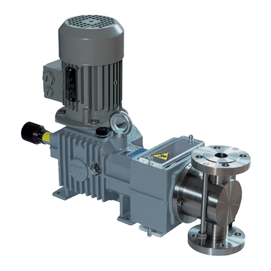
5 PRESENTATION R series plunger pumps are all with a spring return mechanism, coupled to a pump head in chemi- cally material (plastic or metal) that is compatible with the fluid to be dosed. The mechanism body incorporates a transmission reduction gear, a plunger thrust system and a flow rate adjustment sys- tem. -
Page 11: Receiving Inspection
WITH THE COURIER and inform OBL as well. We suggest contacting OBL customer support before commissioning. SUPPLY CONDITIONS All R series pumps are supplied as follows: ready to be installed as specified in the job order pre-tested in accordance with internal specifications... -
Page 12: Overall And Sectional Drawings
5.3.1 OVERALL AND SECTIONAL DRAWINGS Given the importance of these documents (which can undergo further changes or updates), they are not considered part of this instructions manual. Unless otherwise agreed, they are therefore manually attached (latest edition). PERSONNEL RESPONSIBLE FOR MACHINE OPERATION Personnel must be professionally employed in the sector and suitably trained and must have read and understood the instructions in this manual. -
Page 13: Technical Data
GENERAL DATA 6.1.1 Noise The table below shows the average noise level (lp acoustic pressure) emitted by R series pumps, used within the limits of use and installed in accordance with the instructions in this manual. These average values were detected on the prototype at a distance of 1 metre from the surface of the machine, at a height of 1.6 meters from the service deck and weighted according to curve A. - Page 14 (1) Optional Powering the electric motor with an inverter The pumps must have been expressly ordered for powering via inverter. Otherwise, before their use, the user must contact OBL to define new limits of use (Hz, pressure and flow) that will be guaranteed only after new fitting of pump data plates.
-
Page 15: Technical Data By Pump Type
CONNECTIONS MAX PRESSURE (bar) CODE THREADED FLANGED THREADED A/A- A/A- A-TL VALVES CM 5 CTX 5 R 10 CM 5 CTX 5 R 16 CM 7 VP 7 R 25 CM 7 VP 7 R 30 CM 7 VP 7... -
Page 16: Environmental And Design Temperature
ENVIRONMENTAL AND DESIGN TEMPERATURE Unless otherwise agreed upon with the client, the ambient design temperature "Ta" of the plant for all types of pumps is: –10°C Ta +40°C: Standard temperature range for all pump types The table below illustrates the maximum allowed temperature of pumped fluid based on pump head material. -
Page 17: Storage Conditions
The lifting rings on the pump are sized to withstand the weight of a single-head pump and therefore should not be used to lift multiple pumps. Sling the base with lifting ropes for those operations. Fasten the pump safely to the base before freeing it. Tipping hazard! STORAGE CONDITIONS If not used immediately, the pumps should be stored with suitable covers in a temperate, dry, clean, vibration-free and weatherproof environment. - Page 18 Protects the motor from overloading and/or electrical short circuits ATTENTION: R series plunger pumps are displacement pumps that always require a safety valve, installed externally on the discharge line (see "External safety valve") to protect against any excessive pressure.
- Page 19 To facilitate dismantling of the pump from the system, provide for adequate drainage near the pump head on the discharge pipe. Provide for fitting nozzles to facilitate dismantling of flanged connections (see figure 4). Figure 3 Figure 4 After discharge connection of the pump, we recommend the use of a cross connection, both to fa- cilitate pump dismantling and to allow for (at a later time if necessary) installation of a pressure gauge, safety valve, pulsation dampener (dampener).
-
Page 20: How To Create Suction Pipes
NOTE: Always make the ground connection using the appropriate terminal in the terminal box. HOW TO CREATE SUCTION PIPES It is essential to set up the suction pipe properly to ensure proper pump operation. Especially in the case of installations above the head, the factors to consider are: the internal diameter of the pipe the total length of the pipe the expansion or path of the pipe... - Page 21 INCORRECT INSTALLATION CORRECT INSTALLATION Figure 5 Incorrect Correct The fluid vein breaks at the highest side of the pipe Incorrect Correct The fluid vein breaks and air Suction pipe always remains trapped in the hori- upward zontal part of the pipe Correct Incorrect Internal diameter of suc-...
-
Page 22: Suction Pipe For Viscous Liquids
INCORRECT INSTALLATION CORRECT INSTALLATION Figure 5 Recommended Incorrect Recommended Acceptable 8.2.2 Suction pipe for viscous liquids Pumps for viscous liquid dosing must have been specifically ordered for that use. Where possible, we recommend: use of plunger pumps with few strokes per minute and a large diameter plunger to use, in order of importance, a plunger pump, mechanical diaphragm or, lastly, a hydraulic diaphragm to use pump heads in stainless steel, or else with metal or special material valves... -
Page 23: Suction Filter
INCORRECT INSTALLATION CORRECT INSTALLATION Figure 6 Recommended Incorrect Incorrect Recommended Suction filter It is important that the product dosed is liquid, homogeneous and clean to ensure proper pump op- eration. The use of the filter should not affect the suction capacity of pump. Carefully evaluate the real benefit of using the filter according to the nature and characteristics of the fluid. -
Page 24: Calibration Pot
Maximum pump flow rate Filter mesh Mesh opening (Qmax) (US standard) (mm) Qmax < 15 l/h 0.152 15 l/h < Qmax < 50 l/h 0.251 50 l/h < Qmax < 100 l/h 0.353 100 l/h < Qmax < 300 l/h 0.422 300 l/h <... -
Page 25: Discharge Pipe
DISCHARGE PIPE Avoid setting up the discharge pipe or, worse, installing equipment directly above the pump. If the water surface of the suction tank is higher than that of the target tank, siphoning may be trig- gered (see figure 8). The fluid transfers spontaneously and uncontrolled from the suction tank to the target tank, going through the pump without it being able to control the flow rate in any way. -
Page 26: Pulsation Dampener
The external safety valve must be installed immediately after pump discharge connection and, in any case, before the SHUT-OFF valve (see figure 9). The exhaust must be visible, inspectable and aimed into a suction or drainage tank. Avoid connecting the discharge to the pump suction pipe (re- circulation), especially on small flow rate pumps. - Page 27 Due to its nature, the pump generates pressure peaks in the discharge pipe. In "closed circuit" dos- ing (example: in static mixers, press filters, other pressurised pipes), even if the process does not require constant flow/pressure, we suggest installing a pulsation dampener to absorb/reduce these peaks, to ensure correct dosing.
- Page 28 BOTTLE DAMPENER: Fluids enters in the dampener and directly compresses the air inside it (without any means of separation). Dampener volume is approximately 35 times the pump displacement. Advantages: Less expensive compared to the bladder damper. Does not require pre- loading as it self-manages.
- Page 29 Fluids enters in the dampener and compresses a pre-loaded separation bag or dia- phragm (distension chamber). Dampener volume is approximately 8 times the pump displacement. Advantages: More compact compared to the bottle dampener. Can be installed verti- cally or horizontally. Does not require periodic maintenance or need to be regenerated as the preloading gas always remains closed in the bladder.
-
Page 30: Pressure Gauge
Operating pressure > 1 bar Operating pressure > 1 bar Nozzle/sprayer in discharge Long discharge pipe 8.4.3 Pressure gauge Always install a pressure gauge on the discharge pipe; near the pump, upstream from friction losses and before any other accessory (see previous figure 10). Know and control actual pump operating pressure. -
Page 31: Electric Motor Installation
OBL DISCLAIMS ALL RESPONSIBILITY FOR DAMAGES TO PERSONS OR PROPERTY CAUSED BY IMPROPER INSTALLATION OF MOTORS. 8.6.1 R type pumps The motor (UNEL-MEC compliant) is coupled on the shaft on which the worm reduction gear of the pump is installed. Clean the end of the shaft, lubricate it with oil and then proceed with aligning it without banging and with caution on the input shaft. -
Page 32: Checking And Changing The Direction Of Rotation
Verify the actual NPSH (A) characteristics in the system in relation to the NPSH(R) value of the pump. 8.7.2 Installation conditions a) pump installation and operation should only be carried out under the conditions described in the order. -
Page 33: Checks Before Start-Up
During this first phase, check the actual operating pressure of the pump with a pressure gauge (see "Discharge pipe: Pressure gauge"). This value (max fluctuation of the pointer) must not exceed max- imum pressure indicated on the pump data plate. Figure 12 OIL FILLER PLUG BAND 8.8.1 Checks before start-up... -
Page 34: Abnormal Conditions
b) motor absorption current c) temperature of pumped fluid, if different from room temperature d) maximum surface temperature of the entire pump (max 40 °C on the pump reduction gear body and max 80 °C on the motor) Check that pump suitability is maintained whenever changes in operating conditions occur, such as: modification of one or more process variables (i.e. -
Page 35: Characteristics Of The Machine
This list is indicative; we suggest proceeding as detailed in "Instructions for requesting spare parts". Position Pump type Component name SV * DV * Plunger R, RH Plunger seal (seals pack) Plunger seal (lip seals kit) Valve seat O-ring valve seat O-ring valve container Valve (ball) -
Page 36: Description Of Repairs And/Or Safety Devices
See Chapter 13. Full range of applications for which the equipment has been created R series pumps are destined for dosing non-flammable liquid fluids (acids, alkaline, solvents, etc.) at room temperature or warmed (see "Environmental and design temperature"), suitable for discon- tinuous service (12/24 hours of operation). -
Page 37: Prohibited Uses Of The Machine
PROHIBITED USES OF THE MACHINE It is improper to use the R series pumps as follows: without an external safety valve immediately after a discharge connection and therefore be- fore any accessory for dosing products differing from those established during technical/sales negotiation and... -
Page 38: Environments In Which Use Is Prohibited
See chapter 2 for the declaration of conformity. 9.7.1 Electromagnetic compatibility If installed properly and with direct power supply from the mains, R series pumps comply with emission limits set by regulations relating to electromagnetic compatibility (EMC - General re- quirements for industrial environments). -
Page 39: Additional Note For Atex Pumps
• They only meet the requirements of Group II Category 3, making them suitable for use in Zone 2/22 (No danger during normal operation) ATTENTION: R pumps in ATEX operation are not suitable for use in zone 0/20, nor in zone 1/21! NOTE: In the case of R pumps in ATEX operation, warnings contained in "Metering pump... -
Page 40: Operation
10.1 OPERATING PRINCIPLE R series plunger pumps are all with a spring return mechanism, coupled to a pump head in chemi- cally material (plastic or metal) that is compatible with the fluid to be dosed. The mechanism body incorporates a transmission reduction gear, a plunger thrust system and a flow rate adjustment sys- tem. -
Page 41: Flow Rate
10.2 FLOW RATE R series pump flow rate is not continuous but pulsating, generated by the alternating movement of the plunger and the action of the check valve on the head which determine flow direction (see fig- ure 1). Pump flow rate is adjustable and increases or decreases in direct proportion to the variation of the plunger stroke. -
Page 42: Flow Rate Adjustment System
10.2.1 Flow rate adjustment system Flow rate adjustment is continuous and regular and can be carried out both with the pump stopped and in movement. Activation with the pump running is, however, easier, especially for large diame- ter diaphragm pumps. 10.2.1.1 Manual adjustment with knob and linear vernier The standard model is provided when no particular adjustment system is specifically requested. -
Page 43: Flow Lower Than Expected
10.3.1 Flow lower than expected POSSIBLE CAUSE SOLUTION - Air is entering from the suction pipe - Check pipe and junction tightening junctions - Air trapped in the pump head - Bring pump flow to an adjustment of 100% and maintain there for a short time - Excessive suction height - Reduce suction height... -
Page 44: Flow Irregular Or Higher Than Expected
10.3.2 Flow irregular or higher than expected POSSIBLE CAUSE SOLUTION - Suction pressure higher than discharge - Increase discharge pressure by at least 0.3-0.5 pressure bar (3-5 m) with respect to the suction pressure - Backpressure valve blocked at entry by - Check backpressure valve conditions impurities or set to too low a pressure - Pump valves blocked in an open position - Check pump valves, dismantle and clean thor-... -
Page 45: Instructions Regarding Personal Protective Equipment That Must Be Used
- Lubricating oil low or chemically con- - Check and change lubricating oil if necessary taminated 10.4 Instructions regarding personal protective equipment that must be used. Any operation on the machine must be undertaken in compliance with safety regulations and safety warnings. -
Page 46: Operating Precautions
11.1.1 OPERATING PRECAUTIONS All operations must be performed by qualified personnel. Work on the pump must be authorised by the safety supervisor, after having determined that: a) the power line is disconnected and there is nothing being powered, including any auxiliaries b) any risk of accidental restart has been excluded c) pumped fluid present in the pump head and pipes is not under pressure or chemically haz- ardous... -
Page 47: Periodic Operations
11.1.3 PERIODIC OPERATIONS As a general rule, after first start-up, close initial monitoring is recommended to practically define the maintenance plan and determine the frequency of general inspections and planned mainte- nance. If an abnormality occurs, it is the user's responsibility to consider whether to carry out maintenance earlier. -
Page 48: Dismantling, Replacement And Reassembly
Repaint whenever there is the need to protect exterior surfaces from corrosion. 11.1.3.8 Lubricating oil checks R series pumps are supplied complete with lubricating oil in the reduction gear (unless specifically requested) and ready for operation. Check daily that oil is at the halfway level of the cap and that there are no leaks from the dynamic seals or from the pump caps. -
Page 49: Disconnecting Electrical Connections
Entrust maintenance, repairs and overhauls to experienced and qualified personnel who will restore original equipment conditions. Contact OBL customer support for information. 11.2.1 Disconnecting electrical connections Disconnect all electrical connections before dismantling the pump. Make sure the machine cannot be accidentally restarted. 11.3 CHECKING AND REGISTERING THE PLUNGER SEAL During periodic inspections, check for product leaks on the plunger seal. - Page 50 R type pumps: See figure 20 RH type pumps: See figure 21 The plunger seal (pos. 2) is adjustable. A seals pack composed of several "V" rings in Teflon-graphite (created as per OBL design) provides the water seal during pump operation.
-
Page 51: Head Without Plunger Packing Ring Nut
11.4 VALVE CHECKS/REPLACEMENT 11.4.1 R type pumps with lip seal NOTE: BEFORE dismantling, verify there is no pressure or high temperature in the pipes! Operate with pump OFF. Proceed as follows to check conditions and/or replace valves (see figure... -
Page 52: R Type Pumps With Metal Heads And Pack Seal
: PUMP HEAD COMPONENTS (LIP SEAL) 11.4.2 R type pumps with METAL heads and pack seal NOTE: BEFORE dismantling, verify there is no pressure or high temperature in the pipes! Operate with pump OFF. Proceed as follows to check conditions and/or replace valves (see figure... -
Page 53: R Type Pumps With Plastic Heads And Pack Seal
METAL PUMP HEAD COMPONENTS (PACK SEAL): 11.4.3 R type pumps with PLASTIC heads and pack seal NOTE: BEFORE dismantling, verify there is no pressure or high temperature in the pipes! Operate with pump OFF. Proceed as follows to check conditions and/or replace valves (see figure... - Page 54 15 ATTENTION: The ball (pos.15) MUST rest on its seat (pos.5) on the surface OPPOSITE to the smooth side. Figure 15 R PUMPS PLASTIC PUMP HEAD COMPONENTS (PACK SEAL): File: UT-5134 Copyright © - OBL Metering pumps - All rights reserved...
-
Page 55: Pump Type R-Ts
11.4.4 Pump type R-TS NOTE: BEFORE dismantling, verify there is no pressure or high temperature in the pipes! Operate with pump OFF. Proceed as follows to check conditions and/or replace valves (see figure 16): free the pump from the suction and discharge pipe and perform suitable cleaning remove the valve containers one at a time (pos.14) -
Page 56: Pump Type Rh With Metal Heads
PUMPS: PUMP HEAD COMPONENTS Figure 16 R-TS 11.4.5 Pump type RH with METAL heads NOTE: BEFORE dismantling, verify there is no pressure or high temperature in the pipes! Operate with pump OFF. Proceed as follows to check conditions and/or replace valves (see figure... -
Page 57: Pump Type Rh With Plastic Heads
the seal o-rings (pos.7,8 or 9) must be whole replace components where necessary reassemble everything exactly as shown in figure 17 ATTENTION: The ball (pos.15) MUST rest on its seat (pos.5) on the surface OPPOSITE to the smooth side. Figure 17 RH PUMPS: METAL PUMP HEAD COMPONENTS 11.4.6 Pump type RH with PLASTIC heads NOTE: BEFORE dismantling, verify there is no pressure or high temperature in the pipes! - Page 58 carefully observe and check the direction of assembly of individual components check the cleaning, wear and proper direction of assembly of components the ball (pos.15) MUST be SMOOTH and not have dents or corrosion the valve seat (pos.5) must have a smooth, continuous seal that is free of dents the seal o-rings (pos.8,9 or 55) must be whole replace components where necessary reassemble everything exactly as shown in figure 18...
- Page 59 Figure 18 RH PUMPS: PLASTIC PUMP HEAD COMPONENTS File: UT-5134 Copyright © - OBL Metering pumps - All rights reserved...
- Page 60 11.4.6.1 Lubricating oil changes R series pumps are always supplied complete with lubricating oil (unless specifically requested) and ready for operation. Each pump body in multiple pumps has its own lubrication, independent from the others. Operate individually on each pump body to change all multiple pump lubricating oil.
-
Page 61: Special Maintenance
11.5 SPECIAL MAINTENANCE The following guidelines cover the most common "special" maintenance features that only a maintenance expert can perform. Avoid impromptu operations or attempts, contact OBL customer service for specific information. These maintenance suggestions are not intended as "do-it-yourself" repairs. To per- form such works, specialised technical knowledge is required and operations are to be performed by qualified personnel. -
Page 62: Dismantling The Pump Head
Operations for dismantling the pump head to replace the plunger seal (pos.2 or 4) or to replace the plunger (pos.1) are the same for all types of pumps. We suggest, however, reference to the following figures during operation: R, R-ACV pump types (lip seal): See figure 19 R pump types (pack seal):... -
Page 63: Plunger Checks And/Or Replacement
apply a film of grease (i.e. Vaseline) on the new plunger seal (pos.2 or 4) and inside the seal lips reassemble the head (pos.21) following the instructions backwards as contained in "Disman- tling the pump head" fasten the head with clamping screws (pos.29), see "Pump head tightening torque" 11.5.5 Plunger checks and/or replacement FIRST operate as described in "Dismantling the pump head", then proceed as follows: remove the locking set screw (pos.130) from the crosshead (pos.102) and then remove the... - Page 64 (LIP SEAL) Figure 19 R, R-ACV PUMPS : PUMP HEAD File: UT-5134 Copyright © - OBL Metering pumps - All rights reserved...
- Page 65 (PACK SEAL) Figure 20 R PUMPS PUMP HEAD Figure 21 RH PUMPS: PUMP HEAD File: UT-5134 Copyright © - OBL Metering pumps - All rights reserved...
-
Page 66: Pump Head Tightening Torque
11.5.6 Pump head tightening torque The table below shows the coupling torque for locking the pump head. NOTE: DO NOT USE BULLNOSE PLIERS - DO NOT TEFLON COAT THE THREAD THESE OPERATIONS COMPROMISE THE MECHANICAL RESISTANCE OF THE HEAD The values are purely indicative and refer to temperatures as indicated in "Environmental and de- sign temperature". -
Page 67: Replacing Bearings
in the case of plunger pumps, there is no leakage from the seal on the plunger (if necessary adjust the plunger packing ring nut) in the case of diaphragm pumps, check the water seal on the head (if necessary adjust the tightening torque) checks of any head deformations due to the combined action of temperature and pressure Any defect or irregularity detected during inspections should be promptly removed! -
Page 68: Provisions For Returning Goods To Obl (Pumps Under Warranty)
Ship goods DAP Segrate (DDP Segrate for goods coming from countries outside the EU) al- ways with the relative transport document carrying the RA number to: OBL S.r.l. Via Kenne- dy 12 - 20090 Segrate (MILANO) ITALY File: UT-5134 Copyright ©... -
Page 69: Sender Return Rejected
NOTE: The sender is aware of the criminal penalties for false or misleading and falsifying statements. He is also responsible for damage to persons or property arising from such actions. 12.1.2 SENDER RETURN REJECTED If goods should arrive in OBL: Not adequately cleaned (and/or without a completed declaration of conformity) PUMPS: With pump head inadequately cleaned and/or removed WITHOUT RA number (Authorised Return) on the transport document and/or the package... - Page 70 "Waste" is intended as any substance or object which the holder has decided to or is required to discard. Waste is classified according to the origin, in "urban waste" and "special waste" and, ac- cording to harmfulness, in "hazardous waste" and "non-hazardous waste". Maintenance or demolition pump waste are classified as "special waste"...
-
Page 71: Safe Pump Use
13 SAFE PUMP USE 13.1 WARNINGS METERING PUMPS ARE INDUSTRIAL MACHINERY NOT INTENDED FOR USE BY NON- PROFESSIONAL OPERATORS. THESE INSTRUCTIONS ARE INTENDED FOR QUALIFIED PERSONNEL. ATTENTION: Plunger pumps are displacement pumps that always require a safety valve, installed externally on the discharge line (see "External safety valve") to protect against any ex- cessive pressure. - Page 72 In particular, personnel must be informed of hazards deriving from: live parts rotating or moving parts fluid pumped under pressure and/or corrosive fluid hot surfaces The safety supervisor must ensure and guarantee that: the machine is handled, installed, commissioned, inspected, maintained and repaired by qualified personnel only, who therefore possess: specific technical training and experience knowledge of technical regulations and applicable laws...
- Page 73 OBL S.r.l. Via Kennedy, 12 20090 Segrate (MI) - Italy Tel. +39.02.269191 Fax +39.02.2133893 obl.info@idexcorp.com oblpumps.it...
Need help?
Do you have a question about the R and is the answer not in the manual?
Questions and answers