Table of Contents
Advertisement
Fire
The large capacity, ability to support complex cause and
effect programming and wide range of user-controllable
functions make these panels suitable for a wide range of
projects from sheltered housing to large office
developments as well as many industrial applications.
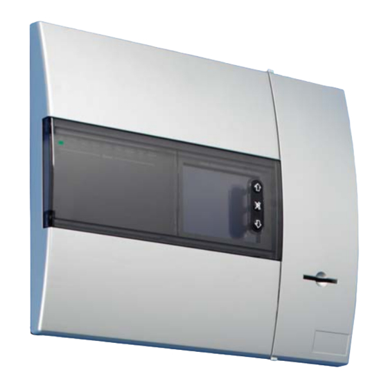
This range of panels provide a large (120mm x 90mm) touch
screen display as the main user element, eliminating the need
for dedicated system push buttons. The user interface is
menu-driven, automatically reconfiguring to suit the chosen
menu option. To enable text updates directly at the panel, the
display converts to a full QWERTY keyboard, enabling
comprehensive text insertion.
The panels also have 96 zone fire LEDs providing additional
information about the extent of any fire activation as well as a
comprehensive set of system status LEDs providing
additional visual information for the end user.
The panels use 'spur tolerant' soft addressing to minimise
installation time and remove the potential for error normally
associated with manual addressing.
CF3000 / DF6000 FX6000
Application Guide
Benefits and Features
>
LPCB 3rd party approved to latest: EN54-2 1997,
A1: 2006 EN54-4 1997, A1: 2002 and A2: 2006
>
VdS, BOSEC, CNBOP Certified
>
Choice of 1, 2 and 4-loop panel options
>
Large multi functional touch screen
>
Spur tolerant soft addressing
>
Short circuit isolators incorporated into each loop
device
>
Up to 200 addresses per loop
>
Fully monitored network capable up to 127 panels
>
Optional integral printer
Advertisement
Table of Contents

Related Manuals for Cooper safety CF3000

Summary of Contents for Cooper safety CF3000
- Page 1 Fire CF3000 / DF6000 FX6000 Application Guide The large capacity, ability to support complex cause and Benefits and Features effect programming and wide range of user-controllable > LPCB 3rd party approved to latest: EN54-2 1997, functions make these panels suitable for a wide range of A1: 2006 EN54-4 1997, A1: 2002 and A2: 2006 projects from sheltered housing to large office...
-
Page 2: Table Of Contents
Download Analogue values and Log to PC Test Device Expected voltage readings Disable all Outputs Auto Learn Analogue Level Printer Settings Programming I/O and Sounders & Sub Menus Change Text Input programming Output programming Add/Delete CF3000 / DF6000 / FX6000 Application Guide... -
Page 3: Recent Amendments
Input/Output devices, FC6 Fan Controller 27 Jul. 10 Output programming 27 Jul. 10 UL 864 9th Edition 16 Aug. 10 T1/T2, Input programming, output prog, network prog, Day/Night, High level menu, Networking, Fan controller and ancillary devices. CF3000 / DF6000 / FX6000 Application Guide... -
Page 4: Menu Structure
APPLICATION GUIDE Menu Structure User Access Code Figure 1 Engineers Menu Figure 2 CF3000 / DF6000 / FX6000 Application Guide... -
Page 5: Zones
Panel 3 would have devices in zones 21 – 30 but none in zones 1 – 20 Access Codes There are 4 access codes for the CF3000 / DF6000 / FX6000. • User Code: This allows control of the silence, evacuate and reset functions and also enable/disable; replace device and check auto config functions. -
Page 6: Replace Device
A delay can be set up on the Sounder control unit in the same way as a loop powered sounder, however, only stage 1 of sounder circuit 1 will accept the delay. The other 3 sounder circuits WILL NOT accept a delay. CF3000 / DF6000 / FX6000 Application Guide... -
Page 7: Double Knock
Selection of the sounder level test mode turn the sounders on for 15 seconds enabling a reading to be taken and then turn them off for 30 seconds allowing the engineer to move on to the next area. CF3000 / DF6000 / FX6000 Application Guide... -
Page 8: One Man Walk Test
If however Autolearn is initiated the devices will be re-numbered and placed into sequence. This method is particular to a DF 4000 to DF 6000 replacement where MAB 728 adaptor plates are used on the existing MAB 700 bases. (The adaptor plate does NOT support Autolearn). CF3000 / DF6000 / FX6000 Application Guide... -
Page 9: Analogue Level
The shop unit interface is not included in the quantity of interface units allowed per loop and always requires a power supply unit. If no power supply is connected then the shop unit interface will show a fault, as it is unable to monitor the sounder circuits. CF3000 / DF6000 / FX6000 Application Guide... - Page 10 ‘Auto enable delays’. This feature enables the user to automatically set T1/T2 at the required times as a backup if the input is missed. (see figure 4) Figure 3 Figure 4 CF3000 / DF6000 / FX6000 Application Guide...
- Page 11 Australian Mode creates a re-configured display screen when class change is shorted. In this mode a key-switch device is installed on the front door of the CF3000 / DF6000 / FX6000 panel which can only be operated by the Australian fire brigade (this key-switch shorts the class change). Address or zone text for the alarm can be viewed on the screen depending on how the screen is configured.
-
Page 12: Change Text
The address text is limited to 24 characters and the zone text should be no more than 32 characters, if the zone text exceeds this then it may over run the display and lose some of the address text CF3000 / DF6000 / FX6000 Application Guide... -
Page 13: Input Programming
NOTE: The addresses must be on the same loop as the input device, whereas the disabling of zones can be achieved across the loop controller. Figure 5 CF3000 / DF6000 / FX6000 Application Guide... -
Page 14: Output Programming
This will effectively double knock the selected zone whereas that zone must have 2 devices in fire to initiate outputs. NOTE: Only 1 zone can be placed in the allocation list. CF3000 / DF6000 / FX6000 Application Guide... - Page 15 APPLICATION GUIDE Figure 6 Figure 7 CF3000 / DF6000 / FX6000 Application Guide...
-
Page 16: Add/Delete
On the network all fires, faults pre-alarms etc. are transmitted to all panels. All user actions such as silence, reset and mute buzzer are also transmitted, so panel 1 could silence the alarms on all other connected panels. CF3000 / DF6000 / FX6000 Application Guide... -
Page 17: Day/Night Setting
Callpoint or I/O must be operated to return this device to dual mode. 5. A half moon indication now appears on the screen between the supervisor button an the clock when day night is in operation. CF3000 / DF6000 / FX6000 Application Guide... -
Page 18: High Level Menu
This menu enables delays to be set on these two outputs. Sounder 1 & Sounder 2 This menu allows the conventional sounder circuits to be set to continuous or pulsing, delayed or double knock CF3000 / DF6000 / FX6000 Application Guide... - Page 19 Earth trouble (fault) now has a separate led indication as well as information on the touch screen and buzzer sounding. T1/T2 remains the same feature but is now called ‘Positive alarm sequence’. Alarm Verification has been slightly enhanced to provide 3 time scales 15, 30 and 60 secs CF3000 / DF6000 / FX6000 Application Guide...
-
Page 20: Networking
The L-Switch Booster is made by a firm called Loytec, and works on a supply voltage of 9-35 v DC. This means that the Easicheck or CF3000 / DF6000 / FX6000 panel external 24v output can power this device. The Booster has two modes of operation ‘Smart Switch mode’... - Page 21 Dual redundant network card is provided. Essentially this device enables the connection of a second network on a card running in parallel with the existing network. This system is configured in the same way as the normal network. CF3000 / DF6000 / FX6000 Application Guide...
-
Page 22: Ancillary Devices
Sounders Sounders, beacons, sounder beacons all appear on the CF3000 / DF6000 / FX6000 device list as alarm/beacons and a maximum of 60 are allowed per loop, the panel and site installer treats them all the same for programming purposes. - Page 23 This device is a Non-Fire input and is identical to the MCIM and MCIM/C. This has been programmed not to indicate a FIRE condition on the panel when in alarm. This allows certain outputs to be programmed to respond to this device without the need to create a fire condition on the panel CF3000 / DF6000 / FX6000 Application Guide...
- Page 24 first to control the feedback the second to provide output and reset controls for the fan In Automatic mode the Fan is controlled by the CF3000 / DF6000 / FX6000 in the normal way through the site installer program.
- Page 25 ‘Download CF3000 / DF6000 / FX6000 text’. This text information is stored in the Display pcb, whereas the device address is stored in the Psu board.
-
Page 26: Getting Started & Fault Diagnosis
Always power down the panel before disconnecting and connecting any PCB wires or cables. Refer to CF3000 / DF6000 / FX6000 Motherboard drawing First confirm the PSU PCB is working correctly. Disconnect the red multiway connector from the PSU and mother board, check it’s continuity. - Page 27 An alternative method, provided a delay has NOT been programmed then go to the enable disable menu and instead of enabling all devices, go to enable disable I/O, and then disable the delays. CF3000 / DF6000 / FX6000 Application Guide...
-
Page 28: Commissioning
1 upwards from the start of each loop, previous addressing is lost. Once the panel has finished the auto-learn it will reset itself. After this is done reset the panel using the touch screen. CF3000 / DF6000 / FX6000 Application Guide... - Page 29 Detector not correctly inserted on base. If a detector is not fully inserted onto a base it is possible that the base switch will not be opened. The newer detectors and bases have a tab to show when the detector is fully inserted. See diagram below. Figure 15 CF3000 / DF6000 / FX6000 Application Guide...
- Page 30 15V (usually over 18V). If the panel is left in this state the end devices will go into fault. The faulty device should be one of the active devices. Figure 17 CF3000 / DF6000 / FX6000 Application Guide...
- Page 31 Check the +ve & -ve cables to screen/earth, ensure greater than 1 Mohm. Check that the screen is not tied to building earth. Repower the panel if the fault remains with the cables disconnected, examine the Pcb’s for contaminants or shorts. CF3000 / DF6000 / FX6000 Application Guide...
- Page 32 Locate the dual addressing devices (see opposite to locate a fault) and fix the problem. Auto-learn the panel, it should no longer reset, if it does repeat the above and locate any further dual addressing problem. CF3000 / DF6000 / FX6000 Application Guide...
-
Page 33: Other Faults
The panel will only run on batteries for one or three days depending on it's configuration. When the mains returns the panel will need resetting to clear this fault. If the fault returns after a reset check the mains input. CF3000 / DF6000 / FX6000 Application Guide... - Page 34 #define ERR_PANEL_HIGH #define ERR_LOOP_LOW #define ERR_LOOP_HIGH #define ERR_ADDR_HIGH #define ERR_ZONE_HIGH #define ERR_LOG_HIGH #define ERR_ZONE_LED_SMALL #define ERR_ZONE_LED_LARGE #define ERR_LOOP_COMMAND #define ERR_ADDR_LOW #define ERR_UNK_LATCH #define ERR_UNK_DEVICE_TYPE #define ERR_DEV_ZONE #define ERR_DEV_TYPE #define ERR_LOOP_DRIVER_HIGH #define ERR_NO_LOOPS #define MAX_ERROR CF3000 / DF6000 / FX6000 Application Guide...
-
Page 35: Programming Issues
Active’, this is associated with a networked system. Following a download the panel address and number of panels in the network can sometimes be returned to 1. Go into the commissioning menu and set up the network address and total number of panels in the network. CF3000 / DF6000 / FX6000 Application Guide... -
Page 36: Program Updates
In the Comm 1 properties box set - 38400 baud, data bits 8, parity none, stop bits 1 and no flow control. Data will now start scrolling down the screen area. Figure 18 CF3000 / DF6000 / FX6000 Application Guide... - Page 37 11. Click "update the panel". 12. It may initially give you a timeout error, if so, just click "update the panel" again. The whole process should take about 5 mins, it is important not to interrupt it. CF3000 / DF6000 / FX6000 Application Guide...
-
Page 38: Panel Comm
French Font test Animation Simulate Fire Backlight on/off Printer Test Printer Status LON Test Debug mode on/off Full Checksum Shutdown/Activate Erase CDR Simulate Fault Simulate Pre-alarm FRE Test Rabbit Test Sounder 1 (Spare) CF3000 / DF6000 / FX6000 Application Guide... -
Page 39: Download Analogue Values And Log To Pc
10. Another box will appear showing the status of the download. 11. Once the file has been downloaded then this can be accessed for reading or printing by ‘right click’ on the file and ‘Open with’ Microsoft Word. Figure 21 Figure 22 CF3000 / DF6000 / FX6000 Application Guide... -
Page 40: Expected Voltage Readings
CF3000 / DF6000 / FX6000 MOTHERBOARD CF3000 / DF6000 / FX6000 Application Guide... - Page 41 NOTES CF3000 / DF6000 / FX6000 Application Guide...
- Page 42 Head Office Sales Tel: 01302 303999 Fax: 01302 303333 Email: sales@cooperfire.com Technical Tel: 01302 303350 Fax: 01302 303332 Email: techsupport@cooperfire.com Export Tel: 01302 303334 Fax: 01302 303345 Email: export@cooperfire.com Srevice Tel: 01302 303352 Fax: 01302 303332 Email: service@cooperfire.com Web: www.cooperfire.com Head Office Cooper Lighting and Safety Ltd Wheatley Hall Road...
Need help?
Do you have a question about the CF3000 and is the answer not in the manual?
Questions and answers