Advertisement
Table of Contents
Advertisement
Table of Contents

Related Manuals for GreenWave Reality PowerNode NP222-B

Summary of Contents for GreenWave Reality PowerNode NP222-B
- Page 1 PowerNodes NP220-B, NP222-B NS220-B, NS222-B...
-
Page 2: Table Of Contents
Table of Contents Introduction PowerNode Overview One-Port PowerNode Multi-Port PowerNode Installation Common Z-Wave Tasks Network Inclusion Process Network Exclusion Process Safety Information About GreenWave Product Specifications... -
Page 3: Introduction
Introduction The GreenWave Reality platform helps create a smart, energy The GreenWave Reality platform helps create a smart, energy-efficient home through the monitoring and efficient home through the monitoring and controlling of your appliances and electronics (referred to as appliances and electronics (referred to as “devices”). You can conserve energy with minimal . -
Page 4: Powernode Overview
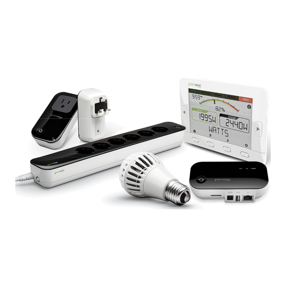
PowerNode Overview The GreenWave Reality PowerNode is a smart outlet adapter that connects your The GreenWave Reality PowerNode is a smart outlet adapter that connects your devices to electrical outlets and to electrical outlets and your GreenWave Reality energy man energy management system so that you can monitor and control your devices’... -
Page 5: One-Port Powernode
One-Port PowerNode PowerNode plug PowerNode plug: Prongs that you plug into your electrical electrical outlet. PowerNode PowerNode socket: Port where you plug in your device. your device. Room color selector Room color selector: Wheel that you rotate to specify the associated room specify the associated room color. -
Page 6: Multi-Port Powernode
Multi-Port PowerNode PowerNode power cord: Power cord that you plug into your electrical outlet. PowerNode sockets: Ports where you plug in your devices. Room color selector: Wheel that you rotate to specify the associated room color. Activity indicator and power on/off button. - Page 7 Room Colors Your PowerNode has a corner wheel with colored numbers to represent the room or device that the PowerNode is powering. Set the PowerNode to the colored number you want to use to identify the room or device (this is referred to as the “room color”). For example, you can set the room color to blue.
- Page 8 one generic grouping when you access your account through the Web or smartphone application. You can still monitor the devices’ energy use information and use them with Smart Controls as if they were categorized under a standard wheel color. The only difference is the manner in which they are grouped under your account.
- Page 9 Indicators Your PowerNode has an indicator that displays any of the following patterns and colors to show you its current status: Off (no color): All PowerNode ports are Steady white in center: All PowerNode ports powered off. are powered on. Steady green in center: Some ports on a Two flashing green bars on each side of multi-port PowerNode are powered on...
-
Page 11: Installation
Sync the PowerNode with your GreenWave Reality Gateway, only if the PowerNode i Sync the PowerNode with your GreenWave Reality Gateway, only if the PowerNode is not part of a package with your Gateway (packages are already synced at the factory). - Page 12 3. Sync the PowerNode with Gateway (if Not Part of Package) Note: If your PowerNode came as part of a package with a GreenWave Reality Gateway, then you can skip this section since the PowerNode and Gateway were already connected at the factory. This section applies only for...
- Page 13 If the PowerNode is not part of a package with a GreenWave Reality Gateway, then you must sync it with your Gateway (a process called “inclusion”) so that the PowerNode and Gateway can communicate with each other. Verify that your Gateway is plugged in and working, and then perform the following steps: Plug the PowerNode into an electrical outlet.
- Page 14 4. Prepare the PowerNode for the Device Make sure the PowerNode is plugged into the electrical outlet. Turn the PowerNode off by pressing the power button, which will illuminate white to indicate the power is off. 5. Plug in the Device and Turn on the PowerNode Plug the device you want to power into the PowerNode port.
- Page 15 overloading. If you would like to control more devices, you can easily add more PowerNodes to your energy management system. Keep radio signals clear. Your Gateway and PowerNodes have antennas built-in for radio communication with Internet services and other devices on your energy management system. Just as you might experience reception problems on your mobile phone inside a building, your Gateway can have trouble communicating with PowerNodes if their radio signals are blocked by obstacles such as large metal panels or walls containing wire mesh.
-
Page 16: Common Z-Wave Tasks
Network Inclusion Process Note: If your PowerNode came as part of a package with Note: If your PowerNode came as part of a package with a GreenWave Reality Gateway, then you c Gateway, then you can skip this section since the PowerNode was already connected at the factory. This section applies only for adding section since the PowerNode was already connected at the factory. - Page 17 To complete the inclusion process perform the following steps: Plug the PowerNode into an electrical outlet. On the Gateway, press and release the sync button once. The activity indicator begins to display a clockwise rotating pattern. When this rotating “inclusion mode” pattern appears on the Gateway activity indicator, the Gateway is ready to be synced with the PowerNode.
-
Page 18: Network Exclusion Process
A PowerNode that has been previously used with a different Z-Wave network must have its association (homeID) with the other network removed before you can connect it to your GreenWave Reality energy management system. This process is called “exclusion” and requires you to perform steps with both the Gateway and the PowerNode. - Page 19 Press and hold the sync button for approximately one second until the PowerNode activity indicator begins to display a counter-clockwise rotating pattern, indicating that the PowerNode is attempting exclusion. During this process, verify that the Gateway activity indicator still displays a counter-clockwise rotating pattern. If not, then the Gateway is not in exclusion mode and you must return to step 2.
-
Page 20: Safety Information
Safety Information Indoor Use Only Your PowerNode should be used only in dry, indoor locations. D Your PowerNode should be used only in dry, indoor locations. Do not use your PowerNode in high o not use your PowerNode in high-humidity locations such as greenhouses, saunas, washrooms, or patios. -
Page 21: About Greenwave
LED lighting. GreenWave Reality is led by a diverse team of proven leaders with global lighting. GreenWave Reality is led by a diverse team of proven leaders with global experience. experience. -
Page 22: Product Specifications
908.42MHz 908.42MHz 908.42MHz Z-Wave Maximum Inter-Node Range (measured with line of sight, no obstacles, and height of devices above floor >1m) GreenWave Reality DeviceDNA v1.0 v1.0 v1.0 v1.0 Operating Temperature 0° C to +40° C 0° C to +40° C 0°... - Page 23 Document Version 1.03 Model Numbers NP220-B, NP222-B, NS220-B, NS220-B...
- Page 24 Federal Communication Commission Interference Statement This device complies with Part 15 of the FCC Rules. Operation is subject to the following two conditions: (1) This device may not cause harmful interference, and (2) this device must accept any interference received, including interference that may cause undesired operation.
- Page 26 (Back Cover)
Need help?
Do you have a question about the PowerNode NP222-B and is the answer not in the manual?
Questions and answers