
Related Manuals for TLD GPU-4060 Series

Summary of Contents for TLD GPU-4060 Series
- Page 1 Operation & Maintenance Manual GPU-4060-T-CUP (& GPU-4060-T-CUP-28) Ground Power Unit...
-
Page 2: Information & Operation
CHAPTER 1 INFORMATION & OPERATION Ground Power Unit GPU-4060-CUP (Version: 200903) -
Page 3: Table Of Contents
Delivering Power to the Aircraft ..................3 Removing Power from the Aircraft................... 4 Shutting Down the Engine ....................4 Specifications and Capabilities...........1-3 ......1 GPU-4060 SERIES ......................1 Generator Specifications ....................1 TLD Generator........................1 Generator Protective System ................... 1 Engines: ..........................2 CUMMINS ENGINE SPECIFICATION:................ -
Page 4: Description
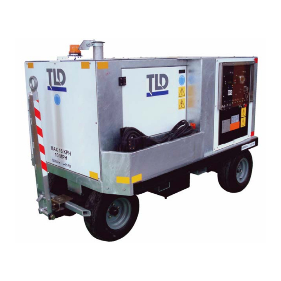
Description 1. Unit Description A. GPU-4060 The GPU-4060 is a self contained, diesel engine driven, ground power unit. The unit is designed to supply regulated 400 Hz electrical power to a parked aircraft for operation of the aircraft's electrical equipment when the on-board generators are not running. components of the GPU-4060 are of a simple but rugged design with sufficient safety devices to ensure a long, trouble free service life. - Page 5 1. Air filter 6. Generator 2. Exhaust silencer 7. Radiator 3. Instrument panel 8. Charge air cooler 4. Engine 9. Electrical Box 5. Fuel Tank GPU-4060 SERIES GROUND POWER UNIT CUMMINS ENGINE CONFIGURATION FIGURE 1 Creation:03.09 — 2009 1-1-2 Description...
-
Page 6: Major Component Description
2. Major Component Description The unit is equipped with 4 cylinders, in-Line, and turbo-charged engine, certified to meet EPA Tier 3 and Euro COM 3 emissions regulations. Since various engines are offered to power the generator, refer to the section that is applicable to your unit. All engines used are equipped with electronic governors, which provide precise frequency regulation and fast transient response. - Page 7 (b) Engine Sensors The engine sensors transmit data to the ECM describing engine dynamic performance. The sensors allow comparison of current engine operating conditions with specific parameters to determine the correct fuel delivery rate. Sensor inputs are supplied for control rod position, speed, coolant temperature, and oil pressure. The data received is used by the ECM to monitor and regulate engine performance, to provide diagnostic information, and to activate the engine protection system.
-
Page 8: Generator System
The GPU-4060 Series generator system is an extremely simple system which contains very few components. It can utilize either the TLD, Kato, or Marathon brand generators. All are direct drop-in replacements. The other major assembly of the generator system is the electrical box assembly, which contains the generator control module, instrument panel controls, and a relay panel. - Page 9 1. Drive plate assembly 9. Endbell 2. Coupling hub 10. Exciter field 3. Screen cover 11. Bearing 4. Adapter 12. Exciter armature 5. Fan assembly 13. Rotating rectifier assembly 6. Aluminum baffle 14. Ring Resistor 7. Generator frame and stator assembly 15.
-
Page 10: Control Box
C. Control Box Electrical Box Assembly: The electrical box assembly is located at the extreme rear of the unit and houses the instrument panel and the relay panel. It also provides a place for the engine’s electronic control module (ECM) to mount to. This is located on the outside of the electrical box back wall and accessed from inside the GPU. - Page 11 Relay Panel Assembly: The relay panel assembly is mounted inside the electrical box on the back wall. The relay panel provides mounting facilities for engine and generator control and protection relays, 3 current transformers, and output load contactor(s). 2) Relay Panel with Spare Relay 1) Relay Panel without Spare Relay 1.
- Page 12 The purpose of the Engine Cooldown Idle Relay is to ensure the engine goes to idle for a period of 1 minute prior to shutting down. This is a standard feature of the GPU-4060 series Ground Power Units designed to protect the engine’s turbo from rapid temperature changes. It will greatly improve the longevity of the engine and it’s logic must not be defeated, Nor should...
- Page 13 (9) Engine Cooldown Timer Module, K7 The purpose of the Engine Cooldown Timer Module is to perform the acutal timing of the Engine Cooldown Circuit. When the engine is running and the ignition switch is moved to the off position, power is cut ot the “initiate” contact of this relay. One minute after, this relay will go back to it’s original state and cut power to the 24 VDC run circuit, cutting power to the engine’s ECM and shutting off the unit.
-
Page 14: Generator Control Module
D. GENERATOR CONTROL MODULE The generator control module is mounted inside the door of the GPU’s electrical box. It’s display is read without opening up the electrical box. The module the waterproof electrical box. The regulator panel provides mounting facilities for the generator control components. The Generator Control Module is designed to provide 1% of voltage regulation with 100 millisecond recovery time for all loads up to 100% of the rated load on all 3 three-phase, four- wire, 115/200 volt, 400 Hz, brushless generators. - Page 15 Generator Control Module Characteristics: The following are the electrical characteristics of the Generator Control Module: Voltage regulation: +/- 1% maximum over full range of generator loading. Voltage transient: 13.8% no load to full load. Voltage transient recovery time: +/- 1% of nominal voltage within 100 milliseconds.
-
Page 16: Instrument Panel
E. Instrument Panel The GPU’s instrument panel is located at the extreme rear of the unit. It provides the operator with controls and displays for generator and engine functioning. 1. Idle / Rated Speed Switch, S6 15. Spare 2. #1 Output Contactor Switch, S10 16. - Page 17 The following instruments and control switches are mounted on the instrument panel. (1) Idle / Rated Speed Switch The engine idle / rated speed switch is a three position toggle switch identical to the output contactor switches. The lower position of the switch is for idle engine speed and the center position of the switch is for full engine speed.
- Page 18 (10) Engine Cool Down Light The engine cool down light will illuminate whenever the engine cooldown relay, K6, is de-energized. This relay is engergized during normal engine running operation and no power is allowed to the light. When the ignition switch is moved to the off position, power is cut from the cooldown timer module, at which time, it’s contacts open after a predetermined time, removeing power to the engine’s ECM and shutting down the engine.
-
Page 19: Contactors
F. Contactors The GPU’s contactors are mounted on the inside bottom surface of the electrical box. The contactor is wired to it’s own bridge rectifier. These components, together with interlock relays) and Note that for 60 KVA GPU’s. (1) Load Contactor and Bridge Rectifier The bridge rectifier receives 400 Hz AC from phase C of the generator output and converts it to a pulsating direct current for energization of the output load contactor holding coil, K10. -
Page 20: Operation
Operation 1. Preparation for Use WARNING: IMPROPER OPERATION CAN KILL! READ AND UNDERSTAND ALL OF THE OPERATING INSTRUCTIONS BEFORE ATTEMPTING TO OPERATE THE UNIT. A. Inspection/Check Inspect the unit thoroughly prior to operation. (1) Remove the blocking, banding, ties, and other securing material. (2) Inspect for shipping damage. -
Page 21: Installing Output Cables
(d) Air Cleaner The air cleaner is a disposable dry type with an integral filter element. Check to ensure there are no papers, tape, or other material covering the air inlet. B. Installing Output Cables Units are generally shipped without aircraft cable assembly. (1) Three-phase AC Aircraft Cable Assembly Installation (#1 Output) The output terminal is located at the left rear of the electrical box. -
Page 22: Unit Operation
2. Unit Operation WARNING: IMPROPER OPERATION CAN KILL! READ AND UNDERSTAND ALL OF THE OPERATING INSTRUCTIONS BEFORE ATTEMPTING TO OPERATE THE UNIT. This section contains information and instructions for the safe and efficient operation of the unit. A. Prestart Inspection (1) Check the engine oil level. -
Page 23: Removing Power From The Aircraft
Removing Power from the Aircraft (1) Place the contactor switch in the "OFF" position. (2) Disconnect the power cable from the aircraft. (3) Stow the power cable on the generator in the proper location. Shutting Down the Engine (1) Turn the ignition switch to “OFF” position. The engine will ramp down to idle and remain in idle for approximately one (1) minute to cool down. -
Page 24: Specifications And Capabilities
Refer to the chart above for power and current rating. Based on the number of poles in the TLD generator, the engine must turn at the speed to obtain the 400 Hz output. The Operating Speed is: 2000 rpm C. -
Page 25: Engines
D. Engines: All engines used are fully-electronic diesel engines with electronic engine governors provide precise frequency regulation and fast transient response. Engine protection such as low oil pressure, high coolant temperature, and over speed protection are programmed into the engine electronic control module. An engine diagnostic connector is provided for communicating with the engine. -
Page 26: Shipping
Shipping 1. Shipping the Unit CAUTION: DO NOT SHIP THE UNIT BY RAIL. DAMAGE MAY OCCUR DUE TO HIGH AND UNPREDICTABLE ACCELERATION WHEN SHIPPING BY RAIL AND THE FACTORY SUGGESTS THAT OTHER MODES OF TRANSPORTATION BE USED. CAUTION: DO NOT USE CHAINS OR STRAPS OVER FUEL LINES, ELECTRICAL WIRES, OR COMPONENTS. -
Page 27: Storing The Unit
Storage 1. Storing the Unit A. When storing the unit in cold ambient temperatures be sure that the proper glycol percentage is present in the engine cooling system. B. When storing the unit for extended periods of time, perform the following steps: (1) Drain the cooling system completely from the engine and radiator.
Need help?
Do you have a question about the GPU-4060 Series and is the answer not in the manual?
Questions and answers