Advertisement
Quick Links
GE Appliances
Training Bulletin
June 2016
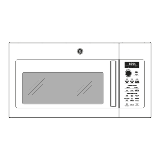
New PVM9179_K Convection Microwave
Features:
• Convection assembly is located on left side
of oven cavity.
• Chef Connect
• Dial and touchpad controls
• 300 CFM exhaust vent fan
• LED cooktop light
• Demo mode
• 1.7 cu. ft. enameled cavity
• 950 watts
• Charcoal filter included for recirculating
configuration
• Removable oven rack and convection rack
Use the complete model number (including engineering digit) when looking up parts.
This Training Bulletin covers some of the differences between the new and previous versions of
the PVM9179.
GE Appliances
Louisville, KY 40225
Microwave/OTR Convection
1
TB13-16
TB13-16
Advertisement

Related Manuals for GE PVM9179*K Series


Summary of Contents for GE PVM9179*K Series
- Page 1 GE Appliances Training Bulletin TB13-16 June 2016 Microwave/OTR Convection New PVM9179_K Convection Microwave Features: • Convection assembly is located on left side of oven cavity. • Chef Connect • Dial and touchpad controls • 300 CFM exhaust vent fan • LED cooktop light •...
- Page 2 Demo Mode -The DEMO MODE is initiated by holding the “POWER LEVEL” and “START/PAUSE” pads at the same time for a full 3 seconds. This mode can only be entered during the initial “PRESS CLOCK” display that occurs when the microwave powers up after a (>25 seconds) power outage. Error Message –...
-
Page 3: Component Access
Component Access Grill – Remove 2 top screws and slide grill to left to Control – Remove grill, remove screw and lift disengage tabs. control up to disengage tabs. Door –Using a small screwdriver, depress the tab on the end cap under the top hinge to remove the end cap. - Page 4 Sensor (humidity/gas) – Remove the grill, squeeze Fuse – Remove grill and remove slotted grill to tabs on each side of the sensor and pull forward to access noise filter board and the fuse mounted to it. disconnect plug. Bottom – Remove seven screws. Turntable motor –...
- Page 5 Magnetron baffle Capacitor Magnetron Cooling fan motor Door switches HV transformer All of the components (except door switches) on this page require removing the case. Magnetron baffle – Remove bottom cover and one bottom screw. Remove two screws on top and one on the side of magnetron.
- Page 6 Convection motor – Remove the case, convection drive belt and the two screws from the motor bracket. Convection Assembly – Remove the case, convection drive belt and motor assembly. Remove ten perimeter screws securing convection assembly to the side of the cavity. The heater TCO is mounted on the convection assembly, if it should open, it will only affect the convection heater.
- Page 7 LED cooktop lights – Remove the bottom and the Exhaust fan motor – Remove three screws from screw securing the glass lens and slide LED rear of cover. Remove two screws securing vent assembly to the left to disengage tabs on left side, cut-out, bend cut-out up to remove motor.
-
Page 10: Main Board Connectors
Main Board Connectors Mini- Manual CN302 Door sensing switch, Hood TCO, oven sensor and CN301 - Humidity Sensor damper switch CN601 Encoder CN702 - Display Module CN204 - Cooktop Light Relay CN703 – Bluetooth Jumper wire to both plugs Module CN203 - Cooktop Light Source CN901 –... - Page 11 COMPONENTS Connectors noted if on the main board Cooktop LED’s CN203 BLACK to YELLOW - ~ 12vdc high -7.5vdc low @ LED connector BLACK to WHITE - ~ 12vdc high – 12vdc low YELLOW to WHITE - 61Ω with Black meter lead on white wire Cooling Fan Motor RED to WHITE –...
Need help?
Do you have a question about the PVM9179*K Series and is the answer not in the manual?
Questions and answers