Table of Contents
Advertisement
Operating and installation instructions
instructions ..................................................2-2
2.0 Notes on possible dangers........................2-2
2.1 Significance of symbols ...................................... 2-2
2.2 Explanatory notes on safety information ............. 2-2
3.0 Storage and transport ...............................2-2
4.0 Description..................................................2-3
4.1 Scope of applications ......................................... 2-3
4.2 Operating principles ............................................ 2-3
4.3 Diagram - assembly ............................................ 2-4
4.4 Technical data - remarks ..................................... 2-6
4.5 Marking ............................................................... 2-6
5.0 Installation...................................................2-7
5.1 General remarks on installation .......................... 2-7
5.2 Installation of accessories ................................... 2-7
5.3 Conversion from notch lever to lock lever ........... 2-8
®
Butterfly valves
BR 012 - ZESA
®
BR 014 - ZIVA
®
-Z
®
THEA) ............................ 2-9
Rev. 0040201000 1617 englisch
BR 013 - GESA
BR 015 - ZIVA
Contents
®
systems .............................................................2-11
6.0 Putting the valve into operation ............. 2-12
7.0 Care and maintenance............................. 2-12
®
7.2 Tightening torques............................................. 2-14
(acc. to EN1515-1) ...................................... 2-15
7.2.3 Bolt material 5.6 - acc. to EN1515-4 ........... 2-15
8.0 Troubleshooting ....................................... 2-16
9.0 Troubleshooting table ............................. 2-16
11.0 Regional Standards................................ 2-17
12.0 Warranty / Guarantee ............................. 2-17
®
®
-G
®
-G).......................................... 2-10
®
-G).......................................... 2-13
2-14
page 2-1
Advertisement
Table of Contents

Related Manuals for ARI-Armaturen BR 012 ZESA

Summary of Contents for ARI-Armaturen BR 012 ZESA
-
Page 1: Table Of Contents
Operating and installation instructions Butterfly valves BR 013 - GESA ® BR 012 - ZESA ® BR 014 - ZIVA ® BR 015 - ZIVA ® Contents 1.0 General information on operating 5.5 Converting or retrofitting lever ® ® instructions ..........2-2 (ZIVA -Z / ZIVA -G).......... -
Page 2: General Information On Operating Instructions
Operating and installation instructions ® ® ® ® ZESA / GESA / ZIVA -Z / ZIVA 1.0 General information on operating instructions These operating instructions provide information on mounting and maintaining the fittings. Please contact the supplier or the manufacturer in case of problems which cannot be solved by reference to the operating instructions. -
Page 3: Description
Operating and installation instructions ® ® ® ® ZESA / GESA / ZIVA -Z / ZIVA 4.0 Description 4.1 Scope of applications Butterfly valves are used for “interruption or restriction of the flow of liquids and gases”. ATTENTION ! - Refer to the data sheet for applications, limits on use and possibilities. - Certain media require or preclude the use of special materials. -
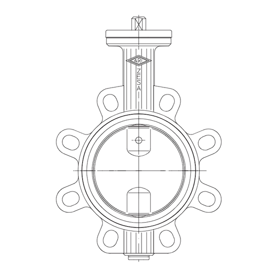
Page 4: Diagram - Assembly
Operating and installation instructions ® ® ® ® ZESA / GESA / ZIVA -Z / ZIVA 4.3 Diagram - assembly rotated view Material designation: EPDM ® ® Fig. 1: Butterfly valve ZESA / GESA Material designation: EPDM ® ® Fig. 2: Butterfly valve ZIVA -Z / ZIVA Refer to the data sheet for information about materials with designations and figure numbers. - Page 5 Operating and installation instructions ® ® ® ® ZESA / GESA / ZIVA -Z / ZIVA Actuation arrangements ® ® Fig. 3: Notch lever ZESA / GESA - The detent pin of the lower lever must be fully disengaged to move the lever. ®...
-
Page 6: Technical Data - Remarks
Operating and installation instructions ® ® ® ® ZESA / GESA / ZIVA -Z / ZIVA Position indicator Lock nut ® ® ® ® Fig. 6: Worm gear ZESA /GESA and ZIVA -Z/ ZIVA - Gear type (actuation by hand wheel, clockwise for closing). The CLOSE-position can be adjusted by ... -
Page 7: Installation
Operating and installation instructions ® ® ® ® ZESA / GESA / ZIVA -Z / ZIVA 5.0 Installation 5.1 General remarks on installation The following points should be taken into account besides the general principles governing installation work: ATTENTION ! - Remove flange covers if present. -
Page 8: Conversion From Notch Lever To Lock Lever
Operating and installation instructions ® ® ® ® ZESA / GESA / ZIVA -Z / ZIVA 5.3 Conversion from notch lever to lock lever window Fig. 7 The notch lever cap (pos. 7) can be used for the conversion. - Set notch lever (pos. 50) to notch position 4. - Slacken socket screw (pos. -
Page 9: Retrofitting The Thermo-Appliance (Zesa ® Thea / Gesa ® Thea)
Operating and installation instructions ® ® ® ® ZESA / GESA / ZIVA -Z / ZIVA ® ® 5.4 Retrofitting the THErmo-Appliance (ZESA THEA / GESA THEA) Fig. 8 - Remove sticker from the hole in the lever (pos. 50). - Insert the THEA temperature indicator (pos. -
Page 10: Converting Or Retrofitting Lever (Ziva ® -Z / Ziva ® -G)
Operating and installation instructions ® ® ® ® ZESA / GESA / ZIVA -Z / ZIVA ® ® 5.5 Converting or retrofitting lever (ZIVA -Z / ZIVA Retrofit in butterfly valve with free shaft end: Fig. 9 ATTENTION ! - Do not remove shaft blowout protection (pos. 26) under pressure. (see point 10.0 Dismantling the valve or the top part) - The valve disc is not fixed in position without an actuating element! - Slacken setscrew (pos. -
Page 11: Installation Instructions For Mounting In Pipe Systems
Operating and installation instructions ® ® ® ® ZESA / GESA / ZIVA -Z / ZIVA 5.6 Installation instructions for mounting in pipe systems Fig. 10-A: Note the open position of the disc at installation! Fig. 10-A Fig. 10-B: Care for sufficient space! Fig. -
Page 12: Putting The Valve Into Operation
Operating and installation instructions ® ® ® ® ZESA / GESA / ZIVA -Z / ZIVA 6.0 Putting the valve into operation ATTENTION ! - Before putting the valve into operation, check material, pressure, temperature and direction of flow. - Regional safety instructions must be adhered to. - Residues in piping and valves (dirt, weld beads, etc.) inevitably lead to leakage. -
Page 13: Changing Seat And O-Ring Seal (Ziva -Z / Ziva -G)
Operating and installation instructions ® ® ® ® ZESA / GESA / ZIVA -Z / ZIVA 7.1 Changing seat and O-ring seal ® ® (ZIVA -Z / ZIVA fig. 10 - Observe safety instructions - Grease seat (pos. 2) when changing Lubricant: e.g. -
Page 14: Tightening Torques
Operating and installation instructions ® ® ® ® ZESA / GESA / ZIVA -Z / ZIVA 7.2 Tightening torques Bolt torques acc. to Roloff-obtain to 0,9xR and RT P0,2 μ = 0,12 / Flange hole acc. to EN1092-1 The actually allowable locking torque can be less than the values shown in the table.This can depend on the kind of bolt material or lubricant is used. -
Page 15: Bolt Material 4.6 - Ari-Data Sheet (Acc. To En1515-1)
Operating and installation instructions ® ® ® ® ZESA / GESA / ZIVA -Z / ZIVA 7.2.2 Bolt material 4.6 - ARI-Data sheet (acc. to EN1515-1) 16 Nm, 240 N/mm P0,2 28 Nm, 240 N/mm P0,2 68 Nm, 240 N/mm P0,2 133 Nm, 240 N/mm... -
Page 16: Troubleshooting
Operating and installation instructions ® ® ® ® ZESA / GESA / ZIVA -Z / ZIVA 8.0 Troubleshooting In the event of malfunction or faulty operating performance check that the installation and adjustment work has been carried out and completed in accordance with these Operating Instructions. -
Page 17: Dismantling The Valve Or The Top Part
Technology for the Future. GERMAN QUALITY VALVES ARI-Armaturen Albert Richter GmbH & Co. KG, D-33750 Schloß Holte-Stukenbrock Telephone (+49 5207) 994-0 Telefax (+49 5207) 994-158 or 159 Internet: http://www.ari-armaturen.com E-mail: info.vertrieb@ari-armaturen.com Page 2-17 Rev.
Need help?
Do you have a question about the BR 012 ZESA and is the answer not in the manual?
Questions and answers