Table of Contents
Advertisement
Quick Links
Technical Data Sheet FSC-UFC24
Universal Field Controller for motorized fire and smoke extraction dampers.
For bus (Modbus or BACnet) or analog integration into a superior system.
Content
Section (continuation)
Technical Data
Cable Specification
Dimensions
Removing the Cover of the Housing
Electrical Installation
Power Supply
Modbus and BACnet Addressing
Configuration through Dip-Switch
Connection Details
Technical Data
Electrical Data Nominal Voltage
Communication / Modbus Protocol
Page 1 of 18
Nominal Voltage Range
Dimensioning
Power Consumption
Connections
Medium
Transmission Formats
Number of Devices per Line
Baud Rates
Address
Termination
Typical Response Time
November 2017
Page
Section (continuation)
1
Thermoelectric Tripping Device - Connection
4
Smoke Detectors – Connections
5
Analog Application
6
Electrical Installation for Analog Application
7
Explanation of LEDs
7
Functionality of Test Button
8
Run Time Monitoring of Actuator
9
Full Auto Test Application
10
Bus Monitoring Application
Technical changes reserved
24 V AC / DC
-20%... + 20%
2 VA + damper actuator (max. 24 VA)
2 W + damper actuator
AMP plug-in connections and quick
connections (terminals)
Modbus RTU
RS-485, not electrically isolated
Specified by Modbus RTU Standards
100 (without repeater)
9'600, 19'200, 38'400, 76'800 bps
1..127 (1-10 reserved for FSC-M200)
(0 reserved for broadcast)
120Ω line termination. Jumper
available on extra pin on PCB.
Position of jumper if FSC-UFC24
is last Modbus device in line see
electrical installation, page 7
<200 ms
www.smtec-ag.ch
Page
11
12
13
14
15
16
17
17
18
Advertisement
Table of Contents

Subscribe to Our Youtube Channel
Summary of Contents for SMT FSC-UFC24
- Page 1 1..127 (1-10 reserved for FSC-M200) (0 reserved for broadcast) Termination 120Ω line termination. Jumper available on extra pin on PCB. Position of jumper if FSC-UFC24 is last Modbus device in line see electrical installation, page 7 Typical Response Time <200 ms...
- Page 2 Address 1..127 (0 reserved for broadcast) Termination 120Ω line termination. Jumper available on extra pin on PCB. Position of jumper if FSC-UFC24 is last BACnet device in line see electrical installation, page 7 Typical Response Time <100 ms Device Instant...
- Page 3 All locally valid regulations and requirements must be observed. Product Features / Application The FSC-UFC24 is used together with a fire or smoke extraction damper actuator to control and monitor one fire or smoke extraction damper. It offers Modbus, BACnet or analog connection and is normally mounted at or close to the damper.
- Page 4 FSC-UFC24. at one point in one line (no matter middle or end). Up to 1’200 meters and max. 100 FSC-UFC24 with Modbus RTU and 65 FSC-UFC24 with BACnet MS/TP Page 4 of 18 November 2017 Technical changes reserved www.smtec-ag.ch...
-
Page 5: Mounting Bracket
Technical Data Sheet FSC-UFC24 Dimensions FSC-UFC24 120 mm 153 mm 57 mm incl. bracket 116 mm Mounting Bracket 70 mm 153 mm 100 mm 130 mm 4,5 mm diameter Page 5 of 18 November 2017 Technical changes reserved www.smtec-ag.ch... - Page 6 Technical Data Sheet FSC-UFC24 Removing the Cover of the Housing 3. Move the sliding cover 10 mm to the top 1. Open the lid 2. Unlock the screw Open the small lid on the lower end of the housing by flapping up the cover...
-
Page 7: Electrical Installation
The actuator has to be 24V AC and/or DC. Meaning it has to operate with the same voltage (AC or DC) as the FSC-UFC24. There are 2 terminals for the power, in order to make the daisy chain connection for the installer easier. -
Page 8: Modbus And Bacnet Addressing
1 2 3 4 5 6 CONF changed to 38’400 (PIN 5 to ON). 1 2 3 4 5 6 If the FSC-UFC24 is used in combination with the FSC-M60, the addressing needs to be done in consecutive order. Address Switches On... -
Page 9: Configuration Through Dip-Switch
(Modbus register 33, BACnet Object List BV 19). If the FSC-UFC24 is used in connection with the FSC-M60, Pin 3 has to be on ON (BACnet). -
Page 10: Connection Details
Smoke Extraction Damper Actuator – Connections If the actuator is powered up the smoke extraction damper is either open or closed. If the FSC-UFC24 sends the smoke extraction damper actuator the open signal, pin OPEN is powered. If the FSC-UFC24 sends the smoke extraction damper actuator the close signal, pin CLOSE is powered. - Page 11 Technical Data Sheet FSC-UFC24 Thermoelectric Tripping Device - Connection Digital input volt free, normally close as default (can be changed on bus). Factory shorted. When this input is active the damper will close and you can override from the bus.
-
Page 12: Smoke Detectors - Connections
Technical Data Sheet FSC-UFC24 Smoke Detectors – Connections Smoke detector connection Hekatron ORS 142 Possibility to connect one smoke detector communication interface 24V DC 24V DC FSC-UFC24 operating voltage relay contact The ORS 142 may only be connected to Hekatron mainspower devices and matches the existing bases type 143. - Page 13 Technical Data Sheet FSC-UFC24 Analog Application The FSC-UFC24 has the option to work without the bus communication connected. There is one input to open or close the damper, depending on the fire or smoke extraction application. It is also possible to monitor the damper position conventionally through a digital output signal.
-
Page 14: Electrical Installation For Analog Application
Technical Data Sheet FSC-UFC24 Electrical Installation for Analog Application AO.1 Analog Ouput – Signals the Status of FSC-UFC24 0V - No Power to FSC-UFC24 2V - Damper Open 4V - Damper Close 6V - Smoke Detector Alarm 8V - Thermoel. Tripping Device Alarm... -
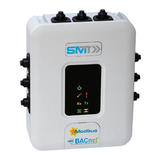
Page 15: Explanation Of Leds
Technical Data Sheet FSC-UFC24 Explanation of LEDs The LEDs are only visible if they are active. If not active the symbols will not appear. 41 mm 61mm Color Action Description Power Green Power is connected Status Yellow Bus operation Analog connection... - Page 16 Depending on the application (fire or smoke extraction) the test button creates different test scenarios. Fire Application: • Power on the FSC-UFC24: actuator (damper) opening until end position is reached • Pushing test button will interrupt the power supply to the actuator. Spring is closing the actuator • As soon as the test button is released the power comes back to the actuator and the damper will open again...
- Page 17 ‘open’ has been sent. Once the timer of the set running time has reached the set time, the FSC-UFC24 will go back into normal operation mode and a feedback ”full auto test ok”...
-
Page 18: Bus Monitoring Application
Bus Monitoring Application The FSC-UFC24 is equipped with a Bus Monitoring Function. If the bus signal to the FSC-UFC24 is interrupted the damper will move to the safety position after the defined period of time and remain there until the bus functionality is back to normal operation.
Need help?
Do you have a question about the FSC-UFC24 and is the answer not in the manual?
Questions and answers