
Summary of Contents for Eli Ezer ERK 7800
-
Page 2: Important Notice
No use of the information contained herein. ERK 7800 reserves the right to make changes in its products or product specifications at any time and without prior notice, and is not required to update this documentation to reflect such changes. -
Page 3: Safety Information
SAFETY INFORMATION Accessory equipment connected to the analog and digital interfaces must be certificated according to the respective IEC/EN standards (e.g. IEC/EN 60950 for data processing equipment and IEC/EN 60601-1 for medical equipment). Furthermore all configurations shall comply with the system standard EN 60601-1-2:2007. If you connect additional equipment to the signal input or signal output of this device, then you are configuring a medical system, and are therefore responsible that the system complies with the requirements of the system standard EN 60601-1-1:2001. - Page 4 SYMBOLS Symbol Descriptions TYPE B EQUIPMENT Protective earth (ground) Alternating current Off (power: disconnected from mains) On (power: connection to mains) Do not dispose of inappropriately Risk of electric shock Crushing hazard sign Hand hazard sign Instruction for user manual General mandatory action sign General prohibition sign General warning, caution sign...
- Page 5 Fragile symbol Recycling symbol Handle with care symbol This way up symbol Manufacturer Manufacturing date...
-
Page 6: General Safety Information
GENERAL SAFETY INFORMATION If you see any warnings or cautions printed on the warning labels, follow the safety instructions in this manual. Ignoring such cautions or warnings while handling the product may result in injury or accident. Be sure to read and fully understand the manual before using this product. -
Page 7: Table Of Contents
INDEX IMPORTANT NOTICE ∙ ∙ ∙ ∙ ∙ ∙ ∙ ∙ ∙ ∙ ∙ ∙ ∙ ∙ ∙ ∙ ∙ ∙ ∙ ∙ ∙ ∙ ∙ ∙ ∙ ∙ ∙ ∙ ∙ ∙ ∙ ∙ ∙ ∙ ∙ ∙ ∙ ∙ ∙ ∙ ∙ ∙ ∙ ∙ ∙ ∙ ∙ ∙ ∙ ∙ ∙ ∙ ∙ ∙ ∙ ∙ ∙ ∙ 1 SAFETY INFORMATION ∙∙... - Page 8 Setup page selection ∙ ∙ ∙ ∙ ∙ ∙ ∙ ∙ ∙ ∙ ∙∙ ∙ ∙ ∙ ∙ ∙ ∙ ∙ ∙ ∙ ∙ ∙ ∙ ∙ ∙ ∙ ∙ ∙ ∙ ∙ ∙ ∙ ∙ ∙ ∙ ∙ ∙ ∙ ∙ ∙ ∙ 30 8.2.1 Measurement setup (MEASURE) ∙...
-
Page 9: Intended Use
Wide dioptric measurement range Because the ERK 7800 covers a wide measurement range from -25D to +22D, even an examinee with strong myopia can be measured. More accurate measurement The fogging method of the eye fixation target makes examinee’s eye comfortable... -
Page 10: Notes For Using The Instrument
Fix the stage by using clamping bolt and stage holding knob, and then lift the bottom of the unit with both hands. 6. When moving the ERK 7800, do not pick up the system using the forehead rest as a grip. - Page 11 proper operation. -. Working condition : Temperature : +10℃ ~ +40℃, Humidity : 30% ~ 90% RH Atmospheric pressure range : 70 kPa ~ 106 kPa Shock (without packaging) : 10g / 6ms -. Storage and Moving condition : Temperature : -40℃ ~ +70℃, Humidity : 10% ~ 95% RH Atmospheric pressure range : 50 kPa ~ 106 kPa Shock : 30g / 6ms, Permanent shock : 10g / 6ms Oscillate(sine curve) : 10Hz ~ 500Hz, 0.5g...
- Page 12 3. Prerequisites for safety 1. Preparation before use -. Do not operate under direct sunlight or too strong lights -. Do not store alchol, thinner and other flammable vapors and liquids in the vicinity of this equipment. -. Check the voltage. -.
-
Page 13: Front Side Of Body
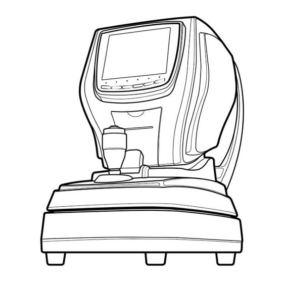
4. Introduction 4.1 Front side of body ① LCD Monitor ② User Keys ③ Measurement ⑦ Printer Button ⑧ Stage Locking Knob ④ Joystick ⑥ Print Button ⑤ Chin Rest Up/Down Button [ Drawing 1 ] Front side Name Functions ①... -
Page 14: Back Side Of Body
4.2 Back side of body ① Head Rest ② Measurement window ⑤ Height ③ Dust Cap aligning mark ④ Chin Rest [ Drawing 2 ] Back side of body Name Function Place the examinee’s forehead against this rest. ① Head Rest ②... - Page 15 4.3 Bottom side of body ⑧ Under Stage Fixing Bolt ① Stage Clamping Bolt ③ RS-232 Connector ② USB Connector ⑥Fuse ④ EXT Video ⑤ Power IN LET ⑦ Power Switch [ Drawing 3 ] Bottom side of body ① Stage Clamping Bolt To clamp the stage during transportation.
- Page 16 4.4 Operation Buttons Button’s functions are displayed in simple word on LCD screen Refer to each mode’s introduction pages for more specific button functions ② ③ ④ ⑤ ⑥ ⑦ ⑧ ⑨ ⑩ ⑪ ⑫ ① [ Drawing 4 ] Operation buttons Name Function ①...
-
Page 17: Equipment Installation And Measurement Preparation
5. Equipment Installation and Measurement Preparation 5.1 Connect power cord - Put ERK 7800 on the table - Plug power cord into power connector - Ensure the power switch is turned OFF, plug power cord into electrical outlet 5.2 Release stage fixing... -
Page 18: Practicing With The Model Eye
6. Practicing with the Model Eye Practice measurement by using the Test Model Eye before measuring patient’s eyes. 6.1 Turn the power ON. 6.2 Remove chin rest paper. Slit the model eye into The pins of the chin rest. 6.3 Make sure the stage is moving freely. Otherwise refer to section 5. - Page 19 6.7 Printout Press the print button on the moving stage to start a printout. If the data preview is set to ON (see section 8.2.2), the results are displayed first. Press the print button a second time to start the printout. <PRINT TYPE-ALL >...
-
Page 20: Measurement Functions
7. Measurement Functions The system main functions comprise refractometry (REF), keratometry (KER), refracto/keratometry (RK), and contact lens base curvature (CLBC) measuring. Additional features are measuring of the corneal radius and observing the cornea. 7.1 Measurement process 7.1.1 Mode selection a. Keep pressing the [MODE] button until the desired mode (REF, KER, RK, CLBC) shows up. b. - Page 21 7.2 REF MODE Only refractometry is performed in the REF mode. Right eye Patient Automatic or number manual shooting 수 수 Number of Step measurements size Cylinder form Right eye measurement result Shooting times Measurement mode [ Drawing 9 ] REF measurement screen 7.2.1 Additional functions a.
- Page 22 7.3 KER MODE In this mode the corneal curvature radius is measured. Right eye Automatic/Manual Patient shooting number Number of measurements Measurement result Shooting time Measurement Mode [ Drawing 11 ] KER measurement screen 7.3.1 Additional functions a. The buttons change when the [FUNCTION] button is pressed. FUNCTION AUTO MODE...
- Page 23 7.4 Keratometry and Refractometry (RK Mode) In this mode the corneal curvature radius and refraction power is measured at the same time. Right eye 수 Patient Automatic/Manual 수 Number shooting Steps Shooting time Cylinder form Measurement result Measurement result Shooting time Shooting time Measurement Mode...
-
Page 24: Measuring Contact Lenses Base Curve (Clbc Mode)
7.5 Measuring contact lenses base curve (CLBC MODE) Measure base curves of contact lens in CLBC mode. 7.5.1 Attach contact lens a. Load lens up after dampen convex part of model eye, back side. Contact Lens [ Drawing 15 ] Attach contact lens 7.5.2 Attach model eye with contact lens a. -
Page 25: Measuring Cornea Size (Size Mode)
7.6 Measuring cornea size (SIZE MODE) This mode allows to check the radius of the cornea or pupil. Enter this mode by pressing the [FUNCTION] and then the [SIZE] button. Measurement result of right Measurement result of left [ Drawing 17 ] SIZE mode screen 7.6.1 Operating buttons a. -
Page 26: Determine Size
7.6.3 Determine Size Measurement [ Drawing 18 ] SIZE Mode screen a. After the measurement button on the joystick has been pressed, the monitor picture freezes and two bars show up. b. Move the yellow bar to the left side of the pupil/cornea using Move the blue bar to the right side using c. -
Page 27: Pupil And Cornea Observing Function (Illum Mode)
7.7 Pupil and cornea observing function (ILLUM Mode) This mode allows to check for cataract, scratches on contact lenses or the cornea. Enter this mode by pressing the [FUNCTION] and then the [ILLUM] button. [ Drawing 19 ] ILLUM Mode screen 7.7.1 Operating buttons a. - Page 28 7.7.2 Measurement [ Drawing 20 ] Measurement screen a. Follow steps 7.1.2 to 7.1.4. b. Press the measurement button of the joystick to perform the measurement. The monitor picture freezes. c. Press the [ZOOM] button to enlarge the image 2x. In zoom mode 4 arrow buttons appear and can be used to move the image.
-
Page 29: User Settings Of Illum Mode
a. Press the [MSR] button to turn on/off the MSR measurement mode, When enabled, the MSR icon and the KERATO ring show up on the screen. b. Focus and measure as described for refractometry in section 7.1 ans 7.2. c. The refraction results show up together with the observed image. 7.7.4 Image list [ Drawing 22 ] Image list a. -
Page 30: Select Data Display By Measurement Mode
8. Other features 8.1 Display measured data 8.1.1 Display mode Enter the display mode by pressing [DISPLAY] button. [ Drawing 23 ] Measured data display 8.1.2 Select data display by measurement mode Press the respective button to see data from refractometry [REF], keratometry [KER], and contact lens base curvature [CLBC]. -
Page 31: Setup Page Selection
8.2 User setup Press [MENU] button to enter the user setup. Choose items with button and set the value with button. 8.2.1 Setup pages selection Press the [PAGE] button to switch through the four setup pages. 8.2.2 Measurement setup (MEASURE) This page contains configuration values concerning the measurement functions. -
Page 32: Printer Setup (Print)
8.2.3 Printer setup (PRINT) Select configuration values concerning printing. [ Drawing 25 ] Printer setup - PRINT TYPE Choose printing contents. ▪ ALL : Print all data. ▪ IMG : Print with the mode of images of myopia. ▪ AVE : Print only average values. -
Page 33: System Setup (System)
[ Drawing 26 ] Setup user message 8.2.4 System setup (SYSTEM) Select configuration values concering the system. [ Drawing 27 ] System setting page - KEY SOUND Turn the sound on/off when a button is pressed or set to middle volume. - LCD BRIGHT Regulate brightness of LCD display from low (1) to high (5). - Page 34 Set display fomat of date. - 24H MODE Set display format of time. - DATE Set present date. a. Press [SET] b. Choose year, month, or day with c. Switch year,month,date with d. Leave setup by pressing repeatedly left or right arrow - TIME Set present time.
-
Page 35: Self-Diagnosis And Maintenance
9. Self-diagnosis and Maintenance 9.1 Before Calling a Service Person Warning messages will be displayed on the monitor if some problems occur. It might be operation errors or problems of the instrument. In this case, refer to the following instructions. If the function is still not recovered, disconnect the power supply and consult the disributor. -
Page 36: Replacement Of Printer Paper
9.2 Replacement of paper 9.2.1 Replacement of printer paper If a red line appears on the paper, or if ‘NO PAPER’ message is displayed on the screen bottom, please replace printer paper with new one. Insert location [ Drawing 29 ] Replacment of printer paper [ Drawing 30 ] Insert location of printer paper a. - Page 37 (1) Repair If a problem cannot be solved even after taking the measures indicated in section 9.1, contact ERK 7800 representative or distributor for repair. Please refer to the name plate and let us have the following information: ▪ Name of the instrument : ERK 7800 ▪...
-
Page 38: Specifications
10. Specifications Refractometry Vertex Distance (VD) 0.0, 10.0, 12.0, 13.5, 15.0 mm Sphere (SPH) -25.00 ~ +22 D (VD 12 mm) Unit : 0.12 / 0.25 D Cylinder (CYL) 0.00 ~ ±10.00 D Unit : 0.12 / 0.25 D 1 ~ 180˚ ˚... - Page 39 11. Components [Drawing 32] ERK 7800 Accesary Nomination Quantity ① Power Supply Cable (USA,CANADA 125V,10A, UL, CUL / EU : 250V, 16A, EN60799, IECEE) Using Plug for US: 120V rating -5-15P type only Caution: Make sure the power cord is the correct type that is required in your area.
- Page 40 If you need to lift and move yourself or fall or be dropped, so please note. Packing to move your fingers when holding the rope, so please note you can get hurt. If the product is damaged packaging may be damaged, so please contact manufacturer or dealer.
- Page 41 EMC (IEC 60601-1-2: 2007) Guidance and manufacturer's declaration - electromagnetic emissions The ERK 7800 is intended for use in the electromagnetic environment specified below. The customer or the user of the ERK 7800 should assure that it is used in such an environment.
- Page 42 Guidance and manufacturer's declaration - electromagnetic immunity The ERK 7800 is intended for use in the electromagnetic environment specified below. The customer or the user of the ERK 7800 should assure that it is used in such an environment. Electromagnetic...
- Page 43 To assess the electromagnetic environment due to fixed RF transmitters, an electromagnetic site survey should be considered. If the measured field strength in the location in which the ERK 7800 is used exceeds the applicable RF compliance level above, the ERK 7800 should be observed to verify normal operation. If abnormal performance is observed, additional measures may be necessary, such as reorienting or relocating the ERK 7800.
- Page 44 RF communications equipment and the ERK 7800 The ERK 7800 is intended for use in an electromagnetic environment in which radiated RF disturbances are controlled. The customer or the user of the ERK 7800 can help prevent electromagnetic interference by maintaining a minimum distance between portable and mobile RF communications equipment (transmitters) and the ERK 7800 as recommended below, according to the maximum output power of the communications equipment.
- Page 45 13. Disposal of waste products When disposing of the products below to contact us ADD: 9990 NW 14 Street , Suite 105 Doral, FL 33172 USA Tel : 888.802.2466 This instrument incorporates a lithium battery, which may pollute the environment if the instrument is disposed. Please ask a professional waste disposal company to handle disposal or your distributor before disposing of the instrument.
Need help?
Do you have a question about the ERK 7800 and is the answer not in the manual?
Questions and answers