Table of Contents
Advertisement
Quick Links
Advertisement
Table of Contents

Summary of Contents for intrepid KM100
- Page 1 User Manual Knikmops Wheel Loaders...
- Page 2 Introduction Copyright and contact details © Miniloaders.com All rights reserved. This document or parts thereof may not be reproduced, copied, distributed or stored in a search system, or sent in any form or method, electronic or otherwise, without written permission from Miniloaders.com.
- Page 3 Preface Make sure that the Knikmops wheel loader is always accompanied by this operator manual. Miniloaders.com is not responsible for damage and indirect damage caused by operator error, lack of (skilled) maintenance or any other use other than described in this manual. Miniloaders.com cannot be held liable for any damages resulting from unauthorized modifications or additions to the Knikmops wheel loader without the written consent of Miniloaders.com Miniloaders.com continually strives to improve her products and services.
- Page 4 Introduction © All rights reserved by Miniloaders.com Use of the operator manual This operator manual provides detailed operating procedures for safe, effective and proper machine use. The manual includes chapters about safe operation, machine specification, maintenance and troubleshooting information. Improper operation, inspection and maintenance of the machine can result in injury or death. Read and understand the contents of this manual completely and become familiar with the machine before operation.
-
Page 5: Table Of Contents
Contents Contents Introduction....................8 About this manual..........................8 Revision history..........................8 Related documents......................... 8 Safety symbols in the document..................... 9 Contact details for North America....................9 Safety......................10 Intended use..........................10 Safety instructions......................... 10 2.2.1 Using the machine......................10 2.2.2 Personnel.......................... 11 2.2.3 Organizational measures....................11 2.2.4 Safety instructions during certain activities................12 2.2.5 Instructions concerning certain risks................. - Page 6 Maintenance table: maintenance with the machine switched on..........33 Periodic maintenance (qualified service technician)..............33 Opening the engine compartment....................34 Opening the engine compartment: type 1 (KM80 to KM100)............34 Opening the engine compartment: type 2 (KM120)..............35 Clean the pre-filter.........................35 Check the fan belt tension......................36...
- Page 7 5.13.1 Other lubrication points......................42 5.13.2 Procedure: lubrication via grease nipples................42 5.13.3 Other lubrication points......................43 Resolving problems.................. 44 Daily maintenance.........................44 Troubleshooting table........................44 Technical data..................46 Consumables..........................46 Reference figure: dimensions......................46 Reference figure: maximum load....................47 KM80.............................48 KM85.............................49 KM100............................50 KM100TE............................51 KM120............................52 KM120TE............................53...
-
Page 8: Introduction
Personnel that carry out daily maintenance on the machine The manual is applicable for these machine types: • KM80 • KM85 • KM100 • KM100TE • KM120 • KM120TE This manual was originally written in Dutch. All other language versions are translations. -
Page 9: Safety Symbols In The Document
Introduction Safety symbols in the document Safety symbol Purpose Description Warning "Warning" means that injury or death is possible if you do not obey the instructions. Caution "Caution" means that damage to the equipment is pos- sible if you do not obey the instructions. Note "Note"... -
Page 10: Safety
Safety Safety Intended use The machine is made for carrying out excavation and transport work in road construction, landscaping and related sectors. By connecting and disconnecting interchangeable accessories, the machine can be used for different applications. Use only interchangeable accessories intended for your machine and that have been approved by the manufacturer. -
Page 11: Personnel
Safety • Counterweights: • Only counterweights and the counterweight frame from the manufacturer may be placed on the rear of the machine. • Persons on the back of the machine are not allowed as counterweight. • Ensure that the interchangeable accessory parts are properly secured at all times. •... -
Page 12: Safety Instructions During Certain Activities
Safety • The machine is suitable for driving on the public highway, provided it has the correct registration documents, the correct traffic lighting and permits. • The workplace must be sufficiently lit at all times. • It is the responsibility of the operator to ensure that bystanders (people who are not the operator) cannot get into the path of the machine, the interchangeable accessories or the loads. -
Page 13: Instructions Concerning Hydraulic Parts
Safety • Avoid shocks and vibrations. • Do not use the machine as an anchor point. 2.2.6 Instructions concerning hydraulic parts The machine and its attachments contain hydraulic components. These involve specific dangers: • The hydraulic oil heats up during use. Contact with hot hydraulic oil can lead to burns. •... - Page 14 Safety Symbol Meaning WARNING: Prevent personal injury or risk of death. • Ensure that safety devices are active. • Work according to the procedures in the user manual. • Keep safety guards in place. • It is forbidden to smoke during maintenance of the machine or refueling.
- Page 15 Safety Symbol Meaning WARNING: • Personnel not controlling the machine must remain at a safe distance from the machine. • Fit the jib lock for maintenance or transport. WARNING: • Before starting the machine, ensure that the interchangea- ble accessory is secured with both locking pins. It is forbidden to stand under the load.
-
Page 16: Description
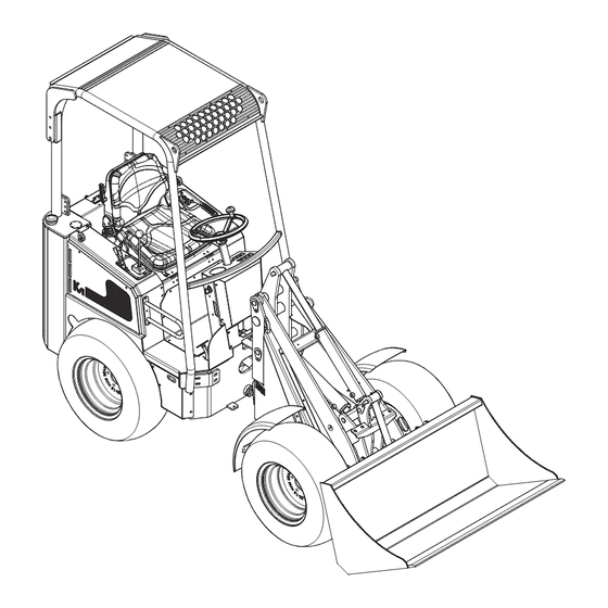
Description Description Overview Safety cabin Driver’s seat Inching pedal Counterweights (optional) Parking brake Hydraulic control Steering wheel Engine compartment Dashboard Fuel tank Lifting eyes and tie-down points Hydraulic fluid tank Boom Jib locking pin Mounting plate Seatbelt Gas pedal 11 - 002 - 30.08.2018... -
Page 17: Type Plate
Description Type plate TYPE POWER MASS/GEWICHT BOUWJ. SERIE NR. MAX. LOAD/LAST MAX. HYDR. 180 BAR MADE IN BELGIUM The illustration shows an example of the layout of the type plate on the machine. The actual type plate on the machine shows the correct data depending on the type of machine. -
Page 18: Dashboard Type 2
Description Fuse box Pre-heater lamp for the diesel engine Light switch Motor temperature lamp Differential switch Operating hours counter Battery voltage lamp 3.3.3 Dashboard type 2 0000000 Ignition key Neutral position indicator Fuse box Engine oil pressure Light switch Battery voltage Differential switch Engine coolant temperature Operating hours counter... -
Page 19: Hydraulic Control
Description Hydraulic control Lever for auxiliary hydraulic function Telescope button (extend) (only for TE left. See also section versions) Lever for auxiliary hydraulic function Moving the joystick left and right takes right. See also section over the function of B. Horn Button to switch the electrical function of the attachment on and off. -
Page 20: Mounting Plate
Description Mounting plate Electrical connection for electrical Mounting plate function. Connection for auxiliary hydraulic Locking handles function right. Connection for auxiliary hydraulic Locking pins function left. 11 - 002 - 30.08.2018... -
Page 21: Sticker For Hydraulic Control And Boom Level Functions
Description Sticker for hydraulic control and boom level functions. LOWER BOOM Auxiliary hydraulic function right RAISE BOOM Auxiliary hydraulic function left MOUNTING PLATE FORWARDS Hydraulic pressure on side hydraulic connection with red dust cap MOUNTING PLATE BACKWARDS Hydraulic pressure on side hydraulic connection with green dust cap 11 - 002 - 30.08.2018... -
Page 22: Driver's Seat
Description Driver’s seat Lever for adjusting the driver's seat Knob for adjusting the backrest forwards and backwards Knob for driver weight adjustment Handle for adjusting the backrest angle Depending on the type of machine, the adjustments of the driver's seat may differ. Operating principle: driving the wheels Hydraulic wheel motors drive the wheels of the machine, one motor per wheel. -
Page 23: Daily Use
Daily use Daily use Starting Safety Warning: Do not exceed the maximum loading. For the specifications, see chapter Preparation Make sure that the daily maintenance has been carried out. See section Check the fuel level and the hydraulic fluid level. Top up the relevant tank if necessary. -
Page 24: Stop
Daily use Stop Stop the machine on flat ground if possible. Place the boom on the ground, if no load is present, or place the load on the ground. Pull the parking brake fully up. Put the following controls in the neutral position: Driving direction lever Boom lever... -
Page 25: Driving
Daily use 4.3.2 Driving Press the parking brake button and fully lower the parking brake. Choose a driving direction: If you want to drive forwards, set the direction button (A) to the 'FORWARD' position (F). If you want to drive in reverse, set the direction button (A) to the 'REVERSE’... -
Page 26: Attaching An Interchangeable Accessory
Daily use Attaching an interchangeable accessory About this task Procedure Release the pressure in the hydraulic system for the auxiliary functions Turn the ignition key to the 'OFF' position to switch off the engine. Move the levers for the auxiliary hydraulic functions back and forth several times to remove the hydraulic pressure. -
Page 27: Refueling
Daily use Procedure Place the interchangeable accessory on the ground. If auxiliary hydraulic functions are connected: Turn off the machine completely. Move the lever for operating the auxiliary hydraulic function that you want to disconnect to and fro to release the pressure in the hydraulic system for the auxiliary functions. -
Page 28: Engaging And Disengaging The Differential
Daily use Procedure Stop the machine. Remove the fuel cap (A). Fill up with fuel. For the correct type of fuel, see section Fit the fuel cap. Engaging and disengaging the differential About this task Caution: In the event of improper use, the tires will show extra wear and the machine will be difficult to steer. -
Page 29: Positioning The Second And Third Counterweight
Daily use Positioning the first counterweight Remove the bolts (A). Remove the panel (B). Position the counterweight (C). Secure the counterweight with the washers and the nuts (D). Fit the panel. Secure the panel with the bolts. Positioning the second and third counterweight Hang the counterweight (A) on the previous counterweight with the hooks (B) -
Page 30: Removal
Daily use Mounting Switch the machine's engine off. Remove the bolt (A). Turn the jib lock (B) towards the tab on the rear part of the machine. Use the bolt (A) to secure the jib lock to the tab. Removal Put the jib lock back on the front part of the machine. -
Page 31: Transport: Safety Instructions
Daily use 4.12.1 Transport: safety instructions About this task Caution: • Do not tow the machine. • Make sure that the machine is not exposed to external shocks, vibrations and collisions. • Protect the machine against external influences such as rain, splashing (salt) water, dirt and dust. -
Page 32: Maintenance
Maintenance Maintenance Daily maintenance Before you begin Warning: Do not touch hot parts of the machine: engine, exhaust and hydraulics. About this task The daily maintenance may be carried out by the machine operator or by someone with an equivalent level of training. Procedure 5.8.1 Lubricate the hinge points. -
Page 33: Maintenance Table: Maintenance With The Machine Switched On
Maintenance Machine part Procedure Rejection criterion Action on rejection Coolant Check the level. See Coolant level not cor- Adjust the coolant lev- 5.10 section rect. el. Procedure: see sec- 5.10 tion Hydraulic fluid Check the level. See Hydraulic fluid level not Adjust the hydraulic flu- 5.11 section... -
Page 34: Opening The Engine Compartment
Maintenance Machine part Task Frequency Procedure Every 150 hours See the diesel engine user manual. Engine oil filter Replace Every 150 hours See the diesel engine user manual. Engine cooling system Check for leaks Daily See the diesel engine user manual. 5.13.3 Other lubrication points Lubricate... -
Page 35: Opening The Engine Compartment: Type 1 (Km80 To Km100)
Maintenance Opening the engine compartment: type 1 (KM80 to KM100) Align the lever (A) with the machine. Open the cover, including the driver's seat (B). Opening the engine compartment: type 2 (KM120) Align the lever (A) with the machine. Open the cover (B). -
Page 36: Check The Fan Belt Tension
Maintenance Procedure Loosen the wing nut (A) on the cover. Remove these parts: • Wing nut • Cover (B) • Filter housing (C) Clean the filter housing. This can be done in various ways: • With compressed air. • With water. Then make sure that the filter housing is dry again. -
Page 37: Checking The Parking Brake
Maintenance Checking the parking brake Pull the parking brake fully up. Try to drive the machine forwards and backwards. If the machine moves forwards or backwards, contact a qualified service technician. 5.8.1 Lubricate the hinge points 5.8.2 Procedure: lubrication via grease nipples Add grease through the grease nipples (see following sections) until grease comes out of the bearing. -
Page 38: Grease Nipples Te Versions
Maintenance 5.8.4 Grease nipples TE versions Grease nipple Grease nipple (only with vertical locking pin) Check/top up the engine oil level Open the engine compartment. See section Remove the engine oil dipstick (A) from the holder, clean the engine oil dipstick and replace it. -
Page 39: Check/Top Up The Coolant Fluid Level
Maintenance Wait 5 minutes and repeat steps 2 and 3 to check if the oil level is correct. Replace the engine oil cap. Close and lock the engine compartment. 5.10 Check/top up the coolant fluid level Safety Warning: Make sure the engine has cooled down sufficiently before carrying out this procedure. -
Page 40: Check And Top Up The Hydraulic Fluid Level
Maintenance 5.11 Check and top up the hydraulic fluid level Before you begin Condition: the temperature of the hydraulic fluid must be approximately 20° C. Procedure Check the liquid level in the sight glass (A). The fluid level must be as far as the bottom red mark (B). -
Page 41: Remove The Cover
Maintenance Remove the cover. Open the engine compartment. See section Remove the cover from the air filter. Press the locking tab (A) upwards. Unscrew the cover (B) counterclockwise. Replace the filter. Remove the old air filter (B). Remove the old fine filter (C). Fit the new filters. -
Page 42: Replacing The Return Filter (Only Present On Certain Machine Types)
Maintenance Replace the intake filter. Remove the side panel (A). Place a container under the drain cap (B). Remove the drain cap. Hydraulic fluid comes out of the drain opening. Remove the intake filter (C). Fit the new intake filter. Refit the side panel. -
Page 43: Other Lubrication Points
Maintenance Procedure Add grease through the grease nipples (see the next section) until grease comes out of the bearing. Use a grease gun. Use the right grease. See section Remove excess grease. Note: It is possible that grease is still released for a longer period of time after lubrication. -
Page 44: Resolving Problems
Resolving problems Resolving problems Daily maintenance Try to resolve the problem using the table to find a resolution for the problem. If you cannot find a solution to the problem, contact a qualified service technician or the manufacturer. Describe the problem in as much detail as possible and clearly indicate what steps you have already taken before contacting the qualified service technician or the manufacturer. - Page 45 Resolving problems Problem Possible cause Possible resolution The machine has fallen over Keep your seat belt on. Stay on the machine. Turn the ignition key to the 'OFF' position to switch off the engine. Do not start the machine again. Oil on top of the piston can damage the en- gine.
-
Page 46: Technical Data
Technical data Technical data Consumables Article Specification Fuel Diesel class EN 590. If in doubt, consult the die- sel engine user manual. Check and follow the regulations of the country where you are located. The use of 'red diesel' is not allowed in certain countries. -
Page 47: Reference Figure: Dimensions
Technical data Reference figure: dimensions Wheelbase Roll bar height / ROPS-FOPS height Total length without bucket Seat height Total length with bucket Ground clearance Total width Tipping-in angle from ground surface Width Jib hinge height Maximum turning angle Transfer height Outside turning circle Shovel bucket rotation point, maximum height... - Page 48 Technical data Reference figure: maximum load Fully retracted boom (smallest torque) Y Fully extended boom (greatest torque) KM80 Table 1: Dimensions Position Parameter Unit Value Wheelbase [mm / in] 1415 / 55.71 Total length without bucket [mm / in] 2360 / 92.91 Total length with bucket [mm / in] 2935 / 115.6...
-
Page 49: Km85
Technical data Position Parameter Unit Value Transfer height [mm / in] 1715 / 67.52 Shovel bucket rotation point, maxi- [mm / in] 1895 / 74.61 Table 2: Maximum load Position Status 1 (X = 830 mm) Not bent [kg / lbs] 700 / 1543 2 (Y = 1205 mm) Not bent... -
Page 50: Km100
Lifting power [kg / lbs] 450 / 992 Breakout force [kg / lbs] 550 / 1220 Speed [km/h / mph] 13 / 8.1 KM100 Table 7: Dimensions Posi- Parameter Unit Value tion Wheelbase [mm / in] 1445 / 56.89... -
Page 51: Km100Te
Technical data Posi- Parameter Unit Value tion Shovel bucket rotation point, maximum [mm / in] 2030 / 79.92 Table 8: Maximum load Position Status Unit Value 1 (X = 820 mm) Not bent [kg / lbs] 910 / 2006 2 (Y = 1235 mm) Not bent [kg / lbs] 730 / 1609... -
Page 52: Km120
Technical data Table 11: Maximum load Position Status Unit Value 1 (X = 995 mm) Not folded, telescopic arm re- [kg / lbs] 800 / 1763 tracted 1 (X = 1800 mm) Not folded, telescopic arm [kg / lbs] 400 / 882 extended 2 (Y = 1475 mm) Not folded, telescopic arm re- [kg / lbs]... -
Page 53: Km120Te
Technical data Posi- Parameter Unit Value tion Jib hinge height [mm / in] 1230 / 48.43 Transfer height [mm / in] 1975 / 77.76 Shovel bucket rotation point, maxi- [mm / in] 2145 / 84.45 Table 14: Maximum load Position Status Unit Value... - Page 54 Technical data Posi- Parameter Unit Value tion Jib hinge height [mm / in] 1320 / 51.97 Transfer height [mm / in] 2420/3030 / 95.28/119.3 Shovel bucket rotation point, maximum [mm / in] 2590/3200 / 102/126 Table 17: Maximum load Position Status Unit Value...
Need help?
Do you have a question about the KM100 and is the answer not in the manual?
Questions and answers
What kind of hydraulic fluid do you use in this loader?
The specific type of hydraulic fluid used in the Intrepid KM100 loader is not provided in the available information. The manual refers to section 7.1 for the correct type of hydraulic fluid, but that section is not included in the provided context. Therefore, the exact fluid type cannot be determined.
This answer is automatically generated