
Summary of Contents for E+L RK 4004
-
Page 1: Table Of Contents
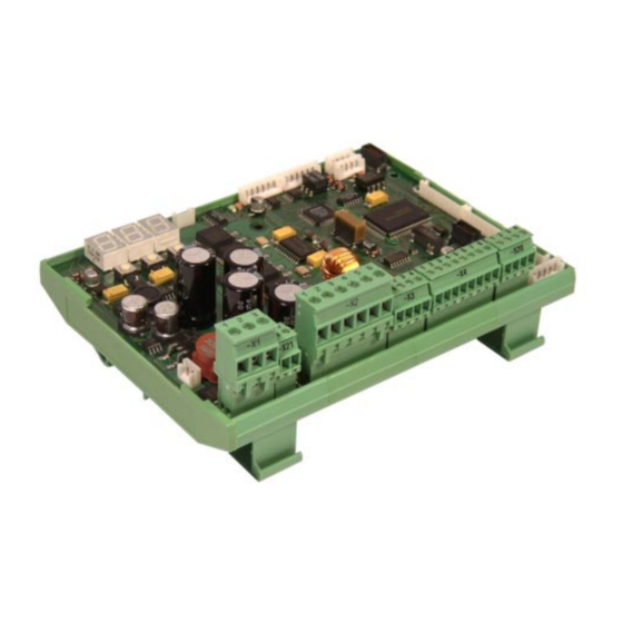
Description J Digital controller RK 4004 Software: RK 4004-0003 F_ZG 1. Function 2. Type overview 3. Assembly 4. Installation 4.1 Terminal assignments X 1 to X 21 4.2 Setup operation 5. Parameters 5.1 Parameter list 5.2 Explanation of parameters 5.3 "Three position controller" upgrade 6. -
Page 2: Function
= important information and instructions 1. Function 1.1 Purpose Controller card RK 4004 is used to control a DC actuator with speed and position feedback. For this purpose a current controller, speed controller, position controller and motor output stage are integrated on the card. - Page 3 Digital controller RK 4004 1.3 Operating principle The operating principle depends on the mode selected. The following operating modes are possible: Actuator manual: In manual mode the actuator may moved to the left or right to a re- quired position. The speed may be set in the appropriate parameter.
- Page 4 Digital controller RK 4004 1.4 Control structure with In a control structure for proportional actuators the web or tool actual constant controlling for position value is compared with the required set position value and, in proportional actuators the event of a deviation, it is transmitted to a P position controller as a control difference.
- Page 5 Digital controller RK 4004 1.5 Control structure with In a control structure for a support beam a set speed value is deter- constant controlling for mined on the basis of the sensor signal via the P position controller support beams that is transmitted to the speed controller.
- Page 6 Digital controller RK 4004 1.6 Control structure with con- In the case of a control structure for integral actuators the web actual stant controlling for inte- position value is compared to the required web set position value gral actuators and, in the event of a deviation, it is transmitted as a control diffe- rence to a P position controller.
-
Page 7: Type Overview
Digital controller RK 4004 The following table provides an overview of the most common digital 2. Type overview controllers. The individual digital controllers (DC) are listed in the ver- tical column. The crosses mark the components belonging to them (AK .., LK .., etc.). -
Page 8: Installation
Digital controller RK 4004 ➜ Connect electrical leads according to the attached wiring diagram. 4. Installation ➜ Shield and run signal lines away from heavy current-carrying leads. The DC actuator motor line must be run separately (separate ca- ble) from the incremental encoder line. -
Page 9: Terminal Assignments X 1 To X
Digital controller RK 4004 4.1 Terminal assign- ments X 1 to X 21 Terminal No. Input Output Assignment +24 V DC supply voltage Ground DC actuator DC actuator Incremental encoder on DC actuator track A Incremental encoder on DC actuator track B... -
Page 10: Setup Operation
Prior to commissioning the device address of controller card device address RK 4004 must be checked and changed as necessary. ➜ Press both keys "decrease value" and "increase value" at the same time. The group number is indicated via the "decrease value "... - Page 11 Digital controller RK 4004 4.2.2 Current error display In normal circumstances the display on the controller card indicates only three dots. These three dots signal that no errors are present . A flashing number signals an error. The number indicates the error code.
- Page 12 Digital controller RK 4004 4.2.3 Parameter setting All parameters in the CAN network may be selected and changed by the three keys. The following flow diagram illustrates basic operation with the setup editor: Basic operation in setup mode: Para- Para-...
-
Page 13: Parameters
Digital controller RK 4004 In setup mode parameters may be displayed and to some extent 5. Parameters changed as well. In order to access the controller card setup mode a command station DO .., a operating panel RT ..or an E+L CANMON program is required. - Page 14 Digital controller RK 4004 Name Default Min. Max. Unit Description .1.0. osc. wave form Oscillation progression 5% = square wave 50% = trapezoidal wave 95% = delta wave .1.1. >osc. trigger mode Oscillation operation 0 (4) = operation via keyboard...
- Page 15 Digital controller RK 4004 Name Default Min. Max. Unit Description .2.9. reserved 29 not assigned at present .3.0. reference offset -3270.0 3270.0 Reference switch offset Distance between reference switching point and AG- positioning range center .3.1. center offset -3270.0 3270.0...
- Page 16 Digital controller RK 4004 Name Default Min. Max. Unit Description .5.2. accel. time 10.0 sec. Acceleration time .5.3. • I-PWM Current I-PWM-value (display only) .5.4. reserved 54 not assigned at present .5.5. • current controller Parameter title .5.6. cut-off current 10.0...
- Page 17 Digital controller RK 4004 Name Default Min. Max. Unit Description .7.5. • temp. case max. Maximal heat sink temperature reached .7.6. reserved 76 not assigned at present .7.7. reserved 77 not assigned at present .7.8. • mainloops/sec. 32000 For internal evaluation only .7.9.
- Page 18 Digital controller RK 4004 Name Default Min. Max. Unit Description .9.7. >function config 1 0801 0000 FFFF System configuration1 [X] Frame limit check 0x0001 [ ] N~ / M control 0x0002 [ ] Center direct 0x0004 [ ] Ref on power on...
- Page 19 Digital controller RK 4004 Name Default Min. Max. Unit Description 1.1.1. reserved 111 not assigned at present 1.1.2. • webspeed config. Parameter title 1.1.3. webspeed constant Normalisation of web speed recording Value corresponds to the input pulse figure per running meter of the web 1.1.4.
-
Page 20: Explanation Of Parameters
CAN address. ..2. reset settings In the event of incorrect functioning or parameter entries, the E+L ba- sic settings or default values may be reloaded. The following settings are possible: 1 = perform customer settings. - Page 21 Digital controller RK 4004 1 = Reset guider In this reset all parameter values for the selected device are sa- ved and a restart performed. Every time parameter values are changed setup mode should always be quit via 1 to assure that all changed parameter values are saved.
- Page 22 "..2. reset settings" . 98 = Delete error memory This command should only be used by E+L service personnel. The controller card can store up to 100 errors that have occur- red. If the number of errors exceeds the 100 mark, the error messages are pushed out at the back of the error memory and are thus deleted.
- Page 23 Digital controller RK 4004 ..4. RK 4004 Parameter value Software version The current software version of the controller card is displayed. The number after the dot indicates the software version. etc. ..5. webedge offset Parameter block for setting the web offset.
- Page 24 Digital controller RK 4004 ..9. osc. cycl. time Cycle-dependent: The cycle time (oscillation time t ) for an oscillation period is esta- blished here. The longer the period, the slower the actuator oscillates. Entry may be directly in the parameter or via a command station with oscillation function.
-
Page 25: Osc. Trigger Mode
Digital controller RK 4004 .1.0. osc. wave form Oscillation mode determines the oscillation course. By entering a va- lue of between 5 and 95 oscillation progression may be changed from square to delta wave. "5" 5 = Square-wave (steep rise/drop of the oscillation signal, long... -
Page 26: Prop Range +/- 10.0 -2000.0 2000.0
Digital controller RK 4004 .1.3. prop range +/- On proportional actuators the amplification of the position con- troller is set via the two parameters ".1.3. Prop range ±" and ".1.6. velocity auto". On integral actuators amplification is set via the two parameters ".1.3. - Page 27 Digital controller RK 4004 By reducing the proportional range the characteristic curve (see fig.) will become steeper. The steeper the characteristic curve the greater the positioning velocity will be in the case of a control deviation and the system thus more sensitive. The positioning velocity of the actua- tor may be determined on the basis of the characteristic curve re- gardless of the control deviation.
-
Page 28: Prop Range +/- Mm
Digital controller RK 4004 Integral actuator: The smaller the set proportional range is for the maximum correction path of the actuator (parameter ".4.5. prop stroke ±"), the greater the amplification of the web guider. A negative proportional range causes negative amplification, the effective direction in automatic mode is thus inverted. - Page 29 Digital controller RK 4004 The values may also be calculated arithmetically: Amplification (G) = parameter .4.5. / parameter .1.3. Correction positioning path (SK) = control deviation * amplication (G) Example 1: Example 2: G = 25/2 = 12.5 G = 25/3.5 = 7.14 SK = 1.5 mm * 12.5...
-
Page 30: Dual-Rate Width
Digital controller RK 4004 .1.4. dual-rate width 50 % .1.5. dual-rate level 70 % Window width = 10.0 mm * 50 % / 100 = 5 mm Reduced pos. velocity = 20 mm/s * 70 % / 100 = 14 mm/s Within ±5 mm of the set web position a web error is corrected at a... -
Page 31: Velocity Pos 50 1000 Mm/S
Digital controller RK 4004 In this example a maximum positioning velocity of 15 mm/s or 20 mm/s has been assumed with a proportional range of 2 mm. Given a maximum positioning velocity of 15 mm/s the positioning velocity amounts to approx. 11 mm/s with a control deviation of 1.5 mm and approx. -
Page 32: Velocity Defect
Digital controller RK 4004 .1.9. velocity defect ".2.2. defect range ±" So that, in the event of a web displacement (e.g. seam joint) the ac- Switching threshold for reducing the po- tuator no longer follows up at maximum positioning velocity in "auto- sitioning velocity matic"... -
Page 33: Motion Direction
Digital controller RK 4004 .2.4. motion direction The positioning direction of the DC actuator drive may be inverted via this parameter. Following inversion of the positioning direction an initialisation run must be performed. .2.5. motion range total The actual positioning path (dimension K) covered by the actuator at the outfeed (transfer roller) must be entered in this parameter. -
Page 34: Reserved
Digital controller RK 4004 Example: Entered value in parameter .2.8. 75 % Entered value in parameter .2.6. / .2.7. = 15 mm 15 mm * 75 / 100 = 11.25 mm If the positioning range of 11.25 mm is exceeded the end position ex- ceeded message will be output. -
Page 35: Center Offset
Digital controller RK 4004 .3.1. center offset DC actuator drive center Center What is termed the "center offset" is the difference between the DC offset actuator drive center and the actuator neutral position. If this neutral position deviates from the positioning path center the former may be changed by entering the "center offset". - Page 36 Digital controller RK 4004 The values for the three parameters .3.4./.3.5./.3.6. must be determi- ned using the table in chapter 6. The mechanical ratio is specified in parameter ".3.7. mech. gear fac- tor". The ratio may be established as follows: Measure distance S 1 between the center of rotation and DC actua- tor drive securing point.
-
Page 37: Reserved
Digital controller RK 4004 .3.8. reserved 38 Not assigned at present. .3.9. reserved 39 Not assigned at present. .4.0. pos. controlling Parameter block for setting the positioning control loop. .4.1. pos prop ± If the position error is greater than the set "position controller propor- tional range"... -
Page 38: Pos Source Adress
Digital controller RK 4004 .4.4. pos source adress In the case of follow-up controlling (master/slave) a second actuator (slave) without sensor scanning precisely follows up a freely selecta- ble actuator (master). The device address of the master's guider must be entered on the controller card of the second actuator (slave). - Page 39 Digital controller RK 4004 Correction path Proportional range .1.3. prop range ± established cor- rection posi- tioning path de- pending on the 15 mm correction posi- 11 mm tioning path Correction path Control deviation .4.5. prop stroke ± 15 mm...
-
Page 40: Photo Auto Offset -2000.0 2000.0
Digital controller RK 4004 .4.6. photo auto offset With a follow-up control/tool control the actuator follows up the actual web position proportionally. To specify the required set postion of the unwinder/tool the offset bet- ween the "center" position and the required set position must be en- tered. - Page 41 Digital controller RK 4004 .5.2. accel. time Positioning Positioning This function is only possible in "manual offset" mode. velocity velocity without In manual mode the actuator is positioned with the positioning veloci- ramp function ty set in parameter ".1.8. velocity jog".
- Page 42 Digital controller RK 4004 .5.8. dyn. currentfactor .5.9. term. timeconst. .6.0. limited current This time-limited excess current is used to increase the dynamics of the DC actuator drive (shorter acceleration time) For a short time a DC actuator drive may be operated with a higher motor current.
- Page 43 Digital controller RK 4004 .6.2. current_P; .6.3. current_I The P and I components of the current controller may be found in the table in chapter 6. The values may not be changed. The values are already optimised at the factory.
- Page 44 Digital controller RK 4004 .7.0. reserved 70 Not assigned at present. .7.1. reserved 71 Not assigned at present. .7.2. running time meter The operating hours of the control card are displayed here. .7.3. supplyvoltage 24 DC The current supply voltage of the controllercard is displayed.
- Page 45 Digital controller RK 4004 .8.2. usage input X 4.1 .8.3. usage input X 4.4 .8.4. usage input X 4.7 .8.5. usage input X20.2 .8.6. usage input X 3.2 The digital inputs (see wiring diagram) may be assigned functions. Each function may only be assigned once.
- Page 46 Digital controller RK 4004 Example 2: The positioning range is to be limited by two separate break contacts. The inputs X 4.4 and X 4.7 should be assigned as follows: Input X 4.4 is assigned the value -6. At signal 0 the negative motor direction of rotation is stopped.
- Page 47 Digital controller RK 4004 .9.2. guider type This parameter is used to determine which type of guider will be used. Proportional actuator Integral actuator Master-Slave Three-level mode mode Pivoting frame Pivoting roller Steering roller Segmented guide rollers Turn rod Edge spreading device...
- Page 48 Digital controller RK 4004 .9.4. auto address The controller card features automatic sensor addressing. Sensor addressing is only performed after a reset and is only pos- sible for sensors that are directly connected to the controller card at connectors X 5/X 6. Furthermore, the sensors must feature the appropriate software for automatic sensor addressing.
- Page 49 [X] Weboffset 1/10 mm 0800 On predecessor controller cards the web offset is always tranmitted in 1/10 mm. Controller card RK 4004 transmits in 1/100 mm. To assure that controller card RK 4004 is compatible to older models this function must be set .
- Page 50 Digital controller RK 4004 The functions may be directly selected with a CANMON program or command station DO 200.. If these two options are not available the sum of the required functions must be formed and this sum value entered in this parame- ter.
- Page 51 Digital controller RK 4004 Example : The "I target-> CAN" and "Disable I Loop" functions are required. Sum value = 0005 + 0008 = 000D Parameter value = 000D .9.9. operatorkey config This parameter is used to activate or deactivate certain functions. The...
- Page 52 Digital controller RK 4004 Example 1: The " Auto: use all sens " and " force support free " functions are requi- red. Sum value = 0001 + 0004 = 0005 Parameter value = 5 Example 2: The " Sens sel. direct ", " emergency sensor L " and "emergency sensor R"...
- Page 53 Parameter block for calibrating the controller card. 1.0.8. calib. UDC Scaling of operating voltage measuring and display. This parameter is automatically set during the test run at E+L. 1.0.9. offset. I-act Motor current offset measuring. This parameter is automatically set during the test run at E+L.
- Page 54 Digital controller RK 4004 1.1.1. reserved 111 Not assigned at present. 1.1.2. webspeed config. Parameter block for setting web speed measuring. 1.1.3. webspeed constant In order to calibrate the web speed measuring function in the control- ler card the no. of pulses that are generated per running meter of the web must be entered here.
- Page 55 Digital controller RK 4004 Example 2: The maximum positioning velocity in "automatic" mode (.1.6.) should be 25% at minimum web speed and 100% at maximum web speed. 1.2.0. The minimum web speed is 5 m/min, the maximum web speed 20 m/ min.
- Page 56 Digital controller RK 4004 1.2.1. reserved 121 Not assigned at present. 1.2.2. reserved 122 Not assigned at present. 1.2.3. reserved 123 Not assigned at present. 1.2.4. reserved 124 Not assigned at present. 1.2.5. !! Service !! This parameter serves only as a parameter title for the following pa- rameters that are grouped together due to their function.
-
Page 57: Three Position Controller" Upgrade
Digital controller RK 4004 For control card applications as a three position controller the va- 5.3 "Three position controller" lue 32 must be entered in parameter "..3. start service" during upgrade control card commissioning. This loads the three position control- ler parameter record. - Page 58 Digital controller RK 4004 .1.6. hysteresis No hysteresis set: on and off switching point at A hysteresis may be set for the three existing switching thresholds 0.4 mm (pulsed, continuous and fastl). The hysteresis allows the switching-off point to lie below the switching-on point by the amount of the hystere- sis.
-
Page 59: Setting Values
Digital controller RK 4004 6. Setting values Type Mat. No. Pulse Trans- Spindle Watts Pos. Current Nominal Speed Speed Current Current per rev mission pitch path speed at 22 V .3.4. .3.5. .3.6. .5.7. .4.8. .5.0. .5.1. .6.2. .6.3. AG 2491... - Page 60 Digital controller RK 4004 Type Mat. No. Pulse Trans- Spindle Watts Pos. Current Nominal Speed Speed Current Current per rev mission pitch path speed at 22 V .3.4. .3.5. .3.6. .5.7. .4.8. .5.0. .5.1. .6.2. .6.3. AG 4571 311805 2750...
-
Page 61: Technical Data
Digital controller RK 4004 Operating voltage 7. Technical Nominal value 24 V DC data Nominal range 20 - 30 V DC (including ripple) Power input without motor/sensors 4,8 W with motor (maximum) 180 W Current input without motor/sensors 0,2 A with motor (maximum) 7.2 A... - Page 62 Erhardt + Leimer GmbH Post box 10 15 40 D-86136 Augsburg Telephone (0821) 24 35-0 Telefax (0821) 24 35-666...
Need help?
Do you have a question about the RK 4004 and is the answer not in the manual?
Questions and answers