Advertisement
Table of Contents
- 1 Mounting Controllers to the 5602 Series Tester
- 2 Relay Board
- 3 Initial Switch Settings
- 4 Veri-Flame No-Purge Models 5602-3X and 5605-3X
- 5 Test Procedure - Set Initial Switch Settings
- 6 Veri-Flame Purge Models 5602-2X and 5605-2X
- 7 Veri-Flame Modulation Models 5602-4X
- 8 Testing External Flame Sensors
- Download this manual
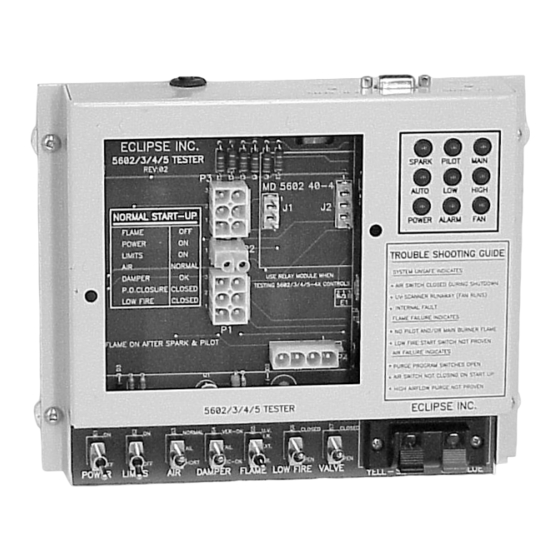
Eclipse Veri-Flame Tester
Relay Board
Model 5603-40-4
Part No. 49240-2
The Model 5602 Tester (pn 49602) provides a convenient means for testing
Veri-Flame controllers and sensors. It also is a good tool for learning about
the sequences and safety features of all the Veri-Flame models. Features
include:
• 7 Toggle switches for simulating inputs
• 9 Lights for controller output status
• 2 Quick-connect terminals for external flame sensor
• Built in flame simulators
• Tests 120V or 240V supply models
NOTE:
The tester is supplied with a standard North American 120VAC plug. The
plug can be cut off and the remaining powercord can be attached to an
appropriate plug or terminal for 240VAC supply.
CAUTION:
The tester must be supplied with the voltage level that matches the Veri-
Flame model being tested.
CAUTION:
Before beginning the test procedures, read the Eclipse Combustion
Instruction Manual 818 and become thoroughly familiar with the controller
model that you are testing.
Mounting Controllers to the 5602 Series Tester
Check the controller model number and DIP-Switch settings to be sure that the
recycling, pilot mode, trial-for-ignition, purge time, and post purge settings are
correct for your application. Be sure the modulation relay board is installed for
modulation model controllers (560x-4x) and unplugged for non-modulating
controllers. Before plugging in the power cord of the tester, seat the controller
firmly in place over the opening on the face of the 5602 Series Tester.
WARNING:
Risk of electrical shock. High voltage is exposed when tester is plugged in
but the Veri-Flame control is removed.
NOTE:
Intermittent pilot operation (DIP-Switch 2 on) means the pilot stays on during
the burner run period. Interrupted pilot (DIP-Switch 2 off) means the pilot will
turn off after the main flame has established.
Initial Switch Settings:
POWER:
LIMITS:
AIR:
CAUTION:
Remove any external flame sensors from the connector block S1 and S2
when using the internal flame simulator.
NOTE:
The internal flame simulators are factory preset. Some adjustment of the UV
signal is possible by turning U.V. SENS. adjustment (on the rear).
and Trainer
DAMPER:
OFF
FLAME:
OFF
LOW FIRE:
NORMAL
VALVE:
Instruction Manual 819
2/11/2011
Model 5602
VER-OK
EXT
CLOSED
CLOSED
Advertisement
Table of Contents

Summary of Contents for Eclipse Veri-Flame 5602
- Page 1 The tester must be supplied with the voltage level that matches the Veri- Flame model being tested. CAUTION: Before beginning the test procedures, read the Eclipse Combustion Instruction Manual 818 and become thoroughly familiar with the controller model that you are testing.
- Page 2 PILOT lights on the tester will come on. 4) Set the FLAME switch to the appropriate position for the flame sensor type of the model under test: FR (down) for flame rods, UV/IR (up) for ultraviolet scanners. Purge Model Eclipse Model 5602 Tester, Instruction Manual 819 2/11/2011...
- Page 3 4) After the selected purge time, the SPARK and PILOT lights on the tester will come on. 5) Set the FLAME switch to the appropriate position for the flame sensor type of the model under test: FR (down) for flame rods, UV/IR (up) for ultraviolet scanners. Eclipse Model 5602 Tester, Instruction Manual 819 2/11/2011...
- Page 4 ALARM light will come on. Testing External Flame Sensors Any Eclipse flame sensor can be tested if the appropriate model Veri-Flame is installed in the tester. Self-check scanners will require a separate 120VAC supply connection to power its internal electronics and shutter. Connect the signal wires to the S1 and S2 connector block.
Need help?
Do you have a question about the Veri-Flame 5602 and is the answer not in the manual?
Questions and answers