Table of Contents
Advertisement
• Controller Hardware Models
• Modes of Operation
• Analog Input Configuration (AI1 to AI4)
• Digital Input Configuration (DI1 and DI2)
• Output Module Configuration (OCN1 to OCN7)
• Programmable Module Configuration (PM1 to PM6)
• External Analog Input Configuration (XAI1 to XAI6)
• Low Limit (Anti-freeze) Module Configuration
• Summer/Winter Compensation Module
• Auto-dial Feature
• Supervisory Functions and Configuration
• Configuration for a TM-9180 Room Command Module
• Mounting
• Wiring
• Jumper and Switch Selections
• Startup
• Commissioning
Specifications & Technical Data
• Ordering Codes
© 2006 Johnson Controls, Inc.
Order No. MN-9100-2120
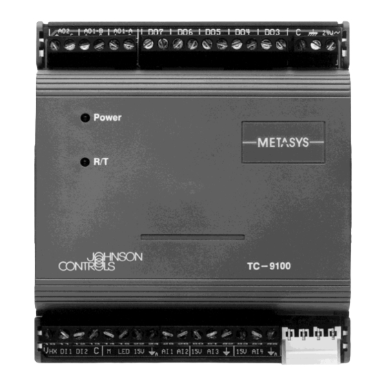
TC-9100 Universal Controller
System 91 Manual
TC-9100 Universal Controller
Technical Bulletin
Issue Date 0306
Page 3
4
5
9
10
13
14
24
39
40
41
42
43
47
49
49
50
56
57
57
59
60
1
Advertisement
Table of Contents

Related Manuals for Metasys TC-9100 Series

Summary of Contents for Metasys TC-9100 Series
- Page 1 System 91 Manual TC-9100 Universal Controller Technical Bulletin Issue Date 0306 TC-9100 Universal Controller Introduction Page 3 • Controller Hardware Models • Modes of Operation Software Configuration • Analog Input Configuration (AI1 to AI4) • Digital Input Configuration (DI1 and DI2) •...
-
Page 2: Table Of Contents
Appendix 1: TC-9100 Item Descriptions and Tables • Table 1: Item List • Table 2: Programmable Module Algorithms Appendix 2: Configuration Worksheets • Worksheet 1: Connections • Worksheet 2: Configuration Parameters – Programmable Modules • Worksheet 3: Configuration Parameters – Input/Output and General Technical Bulletin—TC-9100 Universal Controller... - Page 3 The TC-9100 controller is part of the System 91 series of controllers and is fully compatible with the Metasys network system. The compact size of the controller makes it easy to mount within the terminal unit housing, above a false ceiling or within a small control cabinet.
- Page 4 2333 Figure 3: TM-9180 Room Command Module Note: The TM-9180 Room Command Module is only available as a replacement part from July 2006. There are two models of the TC-9100 Universal Controller. Each model Controller is available with fixed terminals or separable terminals. Hardware Models Table 1: Controller Inputs and Outputs...
- Page 5 Note 1: Digital inputs 1 and 2 may be used with any sensor that provides a dry (voltage-free) and isolated contact, suitable for low-voltage (24 V) switching. Digital Input 1 may also be used with the Johnson Controls Condensation Sensor, code number HX-9100-8001.
- Page 6 Table 2: Standalone Modes Input States: Resulting Modes: Window Contact Occupancy Sensor Operating Mode Alternate Mode (Occupancy Button) Open No Action No Action Closed Occupied COMFORT STANDBY Unoccupied STANDBY COMFORT Depending on the way that the controller is configured, the COMFORT, STANDBY, and OFF modes may change the Working Set Point (WSP) of any control module, and the OFF mode may be configured to override the output of each control module to close off the heating, cooling, or air...
- Page 7 General under the Programmable Module Configuration section of this document. Supervisory systems available from Johnson Controls include the NCM 311/361 in the Metasys Network System, the CS-9105 Control Station, and the Companion System. Note: A supervisory system which is setting the operating mode of the controller will have priority over a locally connected TM-9180 Room Command Module.
- Page 8 This signal may be used to initiate further actions, such as an automatic dial connection to a remote monitoring system. The N2 Dial Module (NDM101) within the Metasys System provides this function. For further details, refer to the section of this document titled Auto-dial Feature.
- Page 9 Software Configuration Preparing a The software operating system of the TC-9100 Universal Controller Configuration contains a number of modules which can be given operating and configuration parameters and connected together to perform the desired control function. Some of the modules condition physical inputs to provide data to other controlling and calculation modules, and some modules control the physical outputs, and the behaviour of all modules is determined by the operating parameters.
- Page 10 Entering a When the worksheet has been completed, the data can be physically Configuration entered into the controller using the SM-9100 Service Module, which plugs into the side of the controller (or by connecting a PC to the N2 Bus serial link and running the M9101 Configuration and Commissioning Software Package).
- Page 11 Item Tag Type Description (Cont.) LRIn Number Low Range for AIn: value represented by the lowest input signal (0 or 2 VDC). This value must be 0 for an input with the square root option. Use OFSn for zero offset correction. The analog value is calculated as follows: Linear: AI = (PI% + OFS) / 100 x (HRI - LRI) + LRI...
- Page 12 Dynamic The parameters that are dynamically generated by the controller from the Parameters analog inputs using the configuration parameters are listed below: Table 5: Analog Input Dynamic Items Item Tag Item Address Description (Hex/Dec) 01/01 Analog Input 1 Value 02/02 Analog Input 2 Value 03/03 Analog Input 3 Value...
- Page 13 Digital Input The TC-9100 Universal Controller has two digital inputs, labeled DI1 and Configuration DI2, each connecting to an isolated, voltage-free contact. DI1 may also be connected to a Condensation Sensor, Order Code HX-9100-8001, which (DI1 and DI2) provides the equivalent of an open contact when the sensor is dry and a closed contact when water condensation is sensed.
- Page 14 The Window Open and Occupancy modes are always active, if defined, and influence the controller operating mode (see tables 2 and 3). The Air Quality / Override and Reverse Action modes are only active for the control modules within which they are enabled. Programmable modules configured as Algorithm 7 to 12 (calculation modules) can be conditioned by one or both of the configured logic modes, enabling the digital inputs to be part of the calculation function (see Programmable Modules...
- Page 15 In both models the digital output pairs OCN3/OCN4 and OCN5/OCN6 can be configured as one of the digital (triac) output options mentioned above for OCN1/OCN2. In addition, the digital outputs OCN5/OCN6/OCN7 can be configured as a 3-speed fan controller, and OCN7 has a special option as a “COMFORT”...
- Page 16 Duration Adjust The DAT output type may be configured in output modules OCN1, Type (DAT) OCN3, and OCN5. The DAT output is a digital output (triac) that is switched on for a duration within the set heating or cooling valve cycle time in direct proportion to the controller output from 0 to 100%.
- Page 17 2-Stage On/Off The 2-stage on/off output type may be configured in pairs of output modules – OCN1/OCN2, OCN3/OCN4, and OCN5/OCN6. The output is a pair of digital outputs (triacs) that are switched on in sequence as the controller output increases. The first stage digital output is switched as soon as the output is above 0% and the second stage digital output is switched when the output is equal to the set load rating for the first stage, which is set as a configuration parameter along with the...
- Page 18 3-Speed Fan The 3-speed fan controller output may be configured only in Output Controller Module OCN5, and it also uses OCN6 and OCN7. Output The output is a set of three digital outputs (triacs) that are switched on in turn at the three fan speed break points, set as configuration parameters. The switching differential for all break points is also set as a configuration parameter.
- Page 19 Note 1: The Override mode is disabled when the controller is in Low Limit (Anti-freeze) mode or in OFF mode. In this case, the 3- speed fan controller operates in Automatic mode and responds as required by the programmable module to which it is connected.
- Page 20 Item Tag Type Description (Cont.) OCN1 Bits 8…6 Output Type 000 = Output not used. Hardware analog outputs only: 001 = Not used. (Was for solenoid valve driver module.) 010 = 0 to 10 VDC output. Hardware digital outputs (triac) only: 011 = On/off output.
- Page 21 Item Tag Type Description (Cont.) OCO3 Number Output Module 3 Parameter . When OCN3 is PAT = Full stroke time of actuator (sec.). When OCN3 is DAT = Cycle time of actuator (sec.). When OCN3 is 2-stage = Load rating of stage 1 (% of module output).
- Page 22 Item Tag Type Description (Cont.) OCN6 1 Byte Output Module 6 Configuration . Bits 5…1 Source of Module in binary code: 01010 (0A hex) = Output Module 1 (OCM1). 01011 (0B hex) = Output Module 2 (OCM2). ⇓ 01111 (0F hex) = Output Module 6 (OCM6).
- Page 23 Dynamic The parameters that are dynamically generated by the controller from the Parameters Output Modules and the associated hardware outputs are listed below: Table 9: Output Module Dynamic Items Item Tag Item Address Description (Hex/Dec) 1F/31, Bit 6 1 = Digital Output 1 On 0 = Digital Output 1 Off 1F/31, Bit 7 1 = Digital Output 2 On...
- Page 24 Programmable The TC-9100 Universal Controller has six programmable modules that may be configured to operate in accordance with one of the 13 algorithms Module Configuration available in the controller operating system. Algorithms 1 to 6 are controller algorithms, and algorithms 7 to 13 are calculation algorithms. (PM1 to PM6) All programmable modules have the same set of configuration parameters, which are listed in Appendix 1 –...
- Page 25 Output OCM = Output Control Module (OCM) = Differential WSP = Working Set Point = Process Variable Input (PV) Figure 7: Reverse-acting (Heating) On/Off Controller Output (OCM) Input (PV) Figure 8: Direct-acting (Cooling) On/Off Controller Proportional/Integral (PI) Controller When configured as a PI controller, the programmable module continuously compares its Input I1, known as the process variable (PV), with its Working Set Point (WSP), and linearly increases its output (OCM) from 0% when the PV is equal to the WSP, to 100% when the PV exceeds...
- Page 26 The following equations define the operation of the PI controller: − × × Proportional Term (P − × × × Integral Term (I − Controller Output (OCM ) = P where , and PV are values at the current time t, is the value one second earlier than the current time, R = (HRIn - LRIn) when PV is connected to AIn (n=1-4), or R = 100 when PV is connected to OCMn.
- Page 27 Working Set Point (WSP) The working set point of a controller is calculated from the internal set point of the controller called the Local Set Point (LSP), Input I2 known as the Remote Set Point (RS), and Input I3 known as the Reference Variable (RV).
- Page 28 Controller Override Mode Priorities The PI controller and on/off controller output may be overridden by one of several Override modes, which are described elsewhere in this manual. The priorities of these Override modes are: Table 10: Override Priorities Priority Mode 1 (highest) Manual OFF Fan Override (3-speed fan control) Low Limit (Anti-freeze) mode...
- Page 29 PM Tag Type Description (Cont.) PMxTYP 2 Bytes Algorithm Options define the behaviour of the programmable module. Bits 5…1 Algorithm Number in binary code: 00001 = Algorithm 1. ⇓ 00110 = Algorithm 6. Bit 6 Enable Low Limit (Anti-freeze) Override for this module: 0 = Not enabled.
- Page 30 PM Tag Type Description (Cont.) PMxTYP Bit 13 Enable Air Quality / Override for this module: 0 = Not enabled. 1 = When the Air Quality/Override Mode (AIRQ) is active (Item Address 20 hex, Bit 8), the output is set to the level specified by the Air Quality/Override Output Level (Bit 14).
- Page 31 Dynamic The parameters that are dynamically generated by programmable Parameters for modules configured to use controller algorithms are listed below: Controller Algorithms Table 12: Programmable Module Dynamic Items for Controller Algorithms Item Tag Item Address Description (Hex/Dec) OCM1 0A/10 Output of Programmable Module 1 OCM2 0B/11 Output of Programmable Module 2...
- Page 32 Loop 1 active Loop 2 active Output (OCMx) DIFx DIFx WSPx WSPx Input (PV) = Process Variable DIFx = Differential Loop 1 OCMx = Output Control Module DIFx = Differential Loop 2 Loops 1 and 2 WSPx = Working Set Point Loop 1 WSPx = Working Set Point Loop 2 Figure 11: Heating/Cooling On/Off Controller –...
- Page 33 Loop 1 active Loop 2 active Output (OCMx) HILx HILx LOLx LOLx Input (PV) WSPx WSPx HILx = High Limit Loop 1 = Process Variable LOLx = Low Limit Loop 1 OCMx = Output Control Module Loops 1 and 2 HILx = High Limit Loop 2 = Proportional Band Loop 1...
- Page 34 Note: When Programmable Module 1 is configured as Algorithm 3, 4, 5 or 6, the L1A bit of LSC (Item Address 26 hex, Bit 4) indicates when the module is active, i.e., when heating is active. When Programmable Module 3 is configured as Algorithm 3, 4, 5 or 6, the L3A bit of LSC (Address 26 hex, Bit 8) indicates when the module is active, i.e., when heating is active.
- Page 35 Algorithm 12: Equation 3 Output (OCM) = [K2 × (I1+K3) × (I2+K4) × (I3+K5) + A] × B (If an input is not connected, the corresponding value In will assume a default value of 1.) In all of the above equations, the variables A and B are determined as follows: if Conditioning Logic Variable 1 = 0 A=K6 if Conditioning Logic Variable 1 = 1...
- Page 36 Configuration The parameters to be defined for each programmable module using a Parameters for calculation algorithm are listed below. Refer to Appendix 2 – Worksheet Calculation 2 , or Appendix 1 – Table 1: Item List , for the Item addresses. In the table Algorithms below, x in the PM Tag name is the programmable module number from 7 to 12...
- Page 37 Dynamic The parameters that are dynamically generated by programmable Parameters for modules configured to use calculation algorithms are listed below: Calculation Algorithms Table 14: Calculation Algorithms 7 to 12 Dynamic Items 7 to 12 Item Tag Item Address Description (Hex/Dec) OCM1 0A/10 Output of Programmable Module 1...
- Page 38 Configuration The parameters to be defined for each programmable module using the Parameters for Line Segment or Signal Span function (Algorithm 13) are listed below. Line Segment Refer to Appendix 2 – Worksheet 2 , or Appendix 1 – Table 1: Item List , Algorithm for the Item addresses.
- Page 39 External The TC-9100 Universal Controller has six external analog inputs that Analog Input may be set by a supervisory system through the N2 Bus serial interface. The numerical value of an external analog input can be used as an input Configuration to a programmable module (configured as a Control Module or as a (XAI1 to XAI6)
- Page 40 Low Limit The TC-9100 Universal Controller has a low limit module with a (Anti-freeze) numerical input connection, a set point parameter, and a low limit Module differential parameter. The output of the module is set to 1 when the value of the input goes below the set point, and returns to 0 when the Configuration value of the input goes above the set point plus the value of the low limit differential.
- Page 41 Summer/Winter The TC-9100 Universal Controller has a Summer/Winter Compensation Compensation module with a numerical input connection, summer and winter set point and authority slope parameters, and two outputs that may be read by a Module supervisory system. The first output (WAC) is active when the value of the input is below the winter set point, and the second output (SAC) is active when the value of the input is above the summer set point.
- Page 42 Feature telephone dial-up connection to a central monitoring station (such as a Metasys NCM or Companion System) whenever it detects that the DIAL Bit (Item XST, Address 84 hex, Bit 5) is set. When the connection has been successfully completed, the central monitoring station will reset the DIAL Bit.
- Page 43 Table 22: Auto-dial Conditions Condition Description AIH n = 1 Analog Input n High Alarm ( n =1-4) AIL n = 1 Analog Input n Low Alarm ( n =1-4) WIN = 1 Window Open ALM = 1 General Alarm AFM = 1 Low Limit (Anti-freeze) Mode Active The TC-9100 Universal Controller may be monitored and controlled by a...
- Page 44 In Hold mode, the output of the module (OCMn) may be written (overridden) by the supervisory system. When the Hold mode is reset, the output is again calculated by the programmable module. The Metasys Network System and Companion System automatically set and reset the Hold modes when the outputs are adjusted and released.
- Page 45 Digital Output Each Digital Output may be controlled directly by the supervisory system Override Control by setting the corresponding Enable Bit. When the Enable Bit is set, the digital output will follow the status of the Control Command Bit and the output control module for the digital output no longer has control.
- Page 46 Table 24: Supervisory Functions Dynamic Items Item Tag Item Address Description (Hex/Dec) 20/32 TC-9100 Operating Status Bits 2,1 Mode Status 00 = NIGHT Mode. 01 = STANDBY Mode. 10 = COMFORT Mode. 11 = OFF Mode. Bit 3 1 = Temporary Alternate Mode Active. Bit 4 1 = Alternate Mode Active.
- Page 47 Item Tag Item Address Description (Cont.) (Hex/Dec) 21/33 Outputs – Supervisory Control Enable DO3E Bit 1 1 = Enable Digital Output 3 for Supervisory Control. DO4E Bit 2 1 = Enable Digital Output 4 for Supervisory Control. DO5E Bit 3 1 = Enable Digital Output 5 for Supervisory Control.
- Page 48 The cooling symbol on the room command module is displayed when the output of Programmable Module 2 is greater than 5%. Therefore Programmable Module 2 must be configured as the main cooling controller for the room. The window symbol on the room command module is displayed when either DI1 or DI2 is configured in Item TCS2 (85 Hex / 133 Decimal) for the Window Open logic mode and the window contact signals that the window is open.
- Page 49 Installation The TC-9100 Universal Controller is designed to be mounted close to the terminal unit equipment being controlled, within a Fan Coil Unit housing for example, or within an electrical control cabinet. The mounting location must be clean and dry, and not subject to extreme heat, cold, or electrical disturbances.
- Page 50 Wiring Before connecting or disconnecting any wires, ensure that all power supplies have been switched off and all wires are potential-free to prevent equipment damage and avoid electrical shock. Terminations are made on the terminal blocks, at the top and bottom of the controller, which accept up to 1.5 mm wires.
- Page 51 24 VAC 24 VAC Live Isolated Switched Outputs Analog Outputs Common 0 - 10 VDC (rated at max. 24 VAC, 0.5 amp) AO1b AO1a Ground – – – 35 34 33 32 31 30 49 48 47 46 45 44 43 42 41 40 Power Common...
- Page 52 24 VAC Live 24 VAC Common Isolated Switched Outputs (rated at maximum 24 VAC, 0.5 amp) Ground 49 48 47 46 45 44 43 42 41 40 39 38 37 36 Power Common Power Digital (Triac) Outputs Supply Digital Inputs Analog Inputs System 91 N2 Communications...
- Page 53 (Old Figure 20 Deleted) 24 VAC ∼ DEC(–) INC(+) n = 1,3,5 TC-9100 Actuator Controller (Incremental / 3 Point) Figure 20: PAT Wiring 24 VAC Stage 2 Stage 2 Stage 1 Stage 1 n = 1,3,5 TC-9100 Stage Control Relays Controller Figure 21: 2-Stage On/Off Wiring Technical Bulletin—TC-9100 Universal Controller...
- Page 54 24 VAC Supply (live) Speed 3 Speed 3 Speed 2 Speed 2 Speed 1 Speed 1 TC-9100 Motor Control Relays Controller Figure 22: 3-Speed Fan Wiring MODE +15V AI1 AI2 TC-9100 14 15 22 24 25 26 Controller Max. 50 m Min.
- Page 55 To Service Module Socket in TC-9100 Controller +15V Extension Cable CLOCK Code: DR-9100-8914 TC-9100 14 15 22 24 Controller Max. 50 m Min. 0.8-mm diameter wire White Blue TM-9180 22 23 14 15 20 Module Service Module utc0tmw Socket Figure 24: Wiring to TM-9180 Room Command Module Note: Set JP3 to left position.
- Page 56 Jumper and To reach the jumpers and switches, open the controller by gripping the Switch cover with thumb and finger on both sides above center and pull the Selections cover off using the lower edge as a hinge. Replace the cover by resting the lower edge of the cover against the base and then pressing the cover firmly to engage all four retaining lugs.
- Page 57 Jumpers for Analog Output 0-10 V Selection AO1a AO1b Power LED Receive/Transmit Address Switches Service Module Socket JP3 (Factory Setting) 2 3 4 5 6 7 8 utc0swi Address Switches Figure 27: TC-9100 Controller Jumpers and Switches When all jumpers and address switches have been set, and all connections Startup have been made and verified, 24 VAC power may be applied.
- Page 58 Technical Bulletin—TC-9100 Universal Controller...
- Page 59 Specifications & Technical Data 24 VAC, ±15%, 50-60 Hz. Supply Voltage 5 VA for controller only (not including power consumption of connected Power Consumption actuator devices). Ambient Operating 0° to 50°C 10 to 90% RH noncondensing Conditions Ambient Storage -40° to 70°C 10 to 90% RH Conditions Terminations...
- Page 60 Outputs Model 1: TC-9100-x000 (Cont.) Two analog outputs: jumper selectable for either: 0 to 10 VDC (10 mA maximum), or: PWM signal for Solenoid Valve Power Driver (not used). Five digital (triac) outputs: rated at 24 VAC (0.5 A maximum). Leakage current 1 mA maximum.
-
Page 61: Appendix 1: Tc-9100 Item Descriptions And Tables
Appendix 1: TC-9100 Item Descriptions and Tables The operating parameters of the TC-9100 (constants, logic variables and analog values), can be accessed through the serial link for control or supervisory purposes. This appendix gives an overview of all of the parameters available in the controller. - Page 62 Floating Point A floating point number in the TC-9100 controller consists of two bytes Numbers using the following bit encoding for the components of the number (in the communications buffer, the two bytes will be in the sequence least significant byte, then most significant byte): where: E3 to E0 4-bit exponent...
-
Page 63: Table 1: Item List
Table 1: Item Type MEM R/W Tag Description Item List Hex Dec 1 Byte UNIT Device Model: 06h General Dynamic Number Analog Input 1 Value Parameters Number Analog Input 2 Value Number Analog Input 3 Value Number Analog Input 4 Value not used not used not used... - Page 64 Item Type MEM R/W Tag Description Hex Dec 2 Bytes Analog Input Alarm Status X1=1 AIH1 Analog Input 1 High Alarm X2=1 AIL1 Analog Input 1 Low Alarm X3=1 AIH2 Analog Input 2 High Alarm X4=1 AIL2 Analog Input 2 Low Alarm X5=1 AIH3 Analog Input 3 High Alarm...
- Page 65 Item Type MEM R/W Tag Description Hex Dec 1 Byte Outputs - Supervisory Control Enable X1=1 DO3E Enable Digital Output 3 X2=1 DO4E Enable Digital Output 4 X3=1 DO5E Enable Digital Output 5 X4=1 DO6E Enable Digital Output 6 X5=1 DO7E Enable Digital Output 7 X6=1...
- Page 66 Item Type MEM R/W Tag Description Hex Dec 1 Byte Supervisory Mode Control X2 X1 MODC Operating Mode Command NIGHT Mode STANDBY Mode COMFORT Mode OFF Mode X3=1 SOFF Shutoff Mode Command X4=1 STUP Startup Mode Command not used X6=1 Supervisory Mode Control X7=1 Manual Operating Mode Command...
- Page 67 Programmable (See Table 2: Programmable Module Algorithms , in this appendix for Module more detailed information.) Configuration Parameters Item Type MEM R/W Tag Description Hex Dec Programmable Module 1 Number PM1K1 Constant K1 Connection D PM1I1@ Input Connection I1 Connection D PM1I2@ Input Connection I2 Connection D PM1I3@ Input Connection I3...
- Page 68 Item Type MEM R/W Tag Description Hex Dec Programmable Module 4 Number PM4K1 Constant K1 Connection D PM4I1@ Input Connection I1 Connection D PM4I2@ Input Connection I2 Connection D PM4I3@ Input Connection I3 2 Bytes PM4TY Options Number PM4K2 Constant K2 Number PM4K3 Constant K3...
- Page 69 Input/Output Item Type MEM R/W Tag Description Configuration Hex Dec Parameters 2 Bytes Firmware Version (binary code) 0001 = Version 2 0002 = Version 3 0003 = Version 4 not used not used Number HIA1 High Alarm Value AI1 Number LOA1 Low Alarm Value AI1 Number...
- Page 70 Item Type MEM R/W Tag Description Hex Dec 1 Byte OCN3 Output 3 Configuration X5...X1 Source of Module in binary code (Numeric Items 0A to 0F, e.g., 0A = 01010) X8...X6 Output Type =000 output not used =011 On/Off Output =100 DAT Output =101...
- Page 71 Item Type MEM R/W Tag Description Hex Dec 1 Byte OCN6 Output 6 Configuration X5...X1 Source of Module in binary code (Numeric Items 0A to 0F, e.g. 0A = 01010), or Source of 3-speed fan override (Numeric Items 01 to 04, e.g. 03 = 00011) X8...X6 Output Type...
- Page 72 General Item Type MEM R/W Tag Description Configuration Hex Dec Parameters not used 2 Bytes Configuration Index 1 2 Bytes Diagnostic Status X4...X1 not used X5=1 RC* DIAL Dial Request Status X8...X6 not used X9=1 XAI1 Unreliable (no external write over the N2 Bus or Service Module since power up) X10=1...
- Page 73 Item Type MEM R/W Tag Description Hex Dec 2 Bytes TCS2 Controller Options 2 X2 X1 ADC Selection Select AI1 Select AI2 Select AI3 Select AI4 X3=1 AI1 not overridden by TM-9180 X4=0 Alternate Mode Timing = 2 Hours X4=1 Alternate Mode Timing = 1 Hour X5=0 not used (Must be set to 0)
- Page 74 Item Type MEM R/W Tag Description Hex Dec Number HRI1 High Range AI1 Number LRI1 Low Range AI1 Number FTC1 Filter Constant AI1 Number OFS1 Offset Value AI1 1 Byte IOP1 Analog Input 1 Options X3...X1 not used X4=0 Input Type: set to 0 (= 0-10V) X7...X5 Input Mode =000...
- Page 75 Item Type MEM R/W Tag Description Hex Dec Summer/Winter Compensation Module Connection D Outdoor Temperature Number Winter Set Point Number Summer Set Point Number Winter Authority Slope Number Summer Authority Slope Low Limit Module Connection D Low Limit (Anti-freeze) Temperature Connection Number Low Limit (Anti-freeze) Set Point...
- Page 76 Item Type MEM R/W Tag Description Hex Dec 2 Bytes CLACT Control Loop Activity X1=1 PM1 Heating X2=1 PM2 Heating X3=1 PM3 Heating X4=1 PM4 Heating X5=1 PM5 Heating X6=1 PM6 Heating not used not used X9=1 PM1 Active X10=1 PM2 Active X11=1 PM3 Active...
-
Page 77: Table 2: Programmable Module Algorithms
Table 2: PM Tag Type Alg. Tag Description Programmable PMxK1 Number Local Set Point Module PMxI1@ Connection Process Variable Source Algorithms PMxI2@ Connection Remote Set Point Source PMxI3@ Connection Reference Variable Source Algorithm 1: PMxTYP 2 Bytes Algorithm Options On/Off Controller X5...X1 Algorithm 1 (00001) X6=1... - Page 78 Algorithm 2: PM Tag Type Alg. Tag Description PI Controller PMxK1 Number Local Set Point PMxI1@ Connection Process Variable Source PMxI2@ Connection Remote Set Point Source PMxI3@ Connection Reference Variable Source PMxTYP 2 Bytes Algorithm Options X5...X1 Algorithm 2 (00010) X6=1 Enable Low Limit (Anti-freeze) Override X7=1...
- Page 79 Heating/Cooling PM Tag Type Alg. Tag Description On/Off Controller Loop 1 –Algorithm 3: PMxK1 Number LSP1 Local Set Point Single Output PMxI1@ Connection PV1@ Process Variable Source Algorithm 5: PMxI2@ Connection RS1@ Remote Set Point Source Dual Output PMxI3@ Connection RV1@ Reference Variable Source PMxTYP...
- Page 80 Heating/Cooling PM Tag Type Alg. Tag Description PI Controller – Loop 1 Algorithm 4: PMxK1 Number LSP1 Local Set Point Single Output PMxI1@ Connection PV1@ Process Variable Source Algorithm 6: PMxI2@ Connection RS1@ Remote Set Point Source Dual Output PMxI3@ Connection RV1@ Reference Variable Source...
- Page 81 PM Tag Type Alg. Tag Description Loop 2 PM(x+1)K1 Number LSP2 Local Set Point PM(x+1)I1@ Connection PV2@ not used PM(x+1)I2@ Connection RS2@ Remote Set Point Source PM(x+1)I3@ Connection RV2@ Reference Variable Source PM(x+1)TYP 2 Bytes TYP2 Algorithm Options X5...X1 not used X6=1 Enable Low Limit (Anti-freeze) Override X7=1...
- Page 82 Algorithm 7: PM Tag Type Alg. Tag Description Average, PMxK1 Number not used Algorithm 8: PMxI1@ Connection Input 1 Source Minimum, PMxI2@ Connection Input 2 Source Algorithm 9: PMxI3@ Connection Input 3 Source Maximum, PMxTYP 2 Bytes Algorithm Options Algorithm 10: X5...X1 Algorithm 7-12 binary code (00111 to 01100) Equation 1,...
- Page 83 Algorithm 13: PM Tag Type Alg. Tag Description Line Segment PMxK1 Number not used Function PMxI1@ Connection Input 1 Source PMxI2@ Connection Input 2 Source PMxI3@ Connection Input 3 Source PMxTYP 2 Bytes Algorithm Options X5...X1 Algorithm 13 (01101) X13...X6 not used X14=1 CND1...
- Page 84 Technical Bulletin—TC-9100 Universal Controller...
-
Page 85: Appendix 2: Configuration Worksheets
Appendix 2: Configuration Worksheets The Configuration Worksheets begin on the next page so that they can be easily reproduced. Technical Bulletin—TC-9100 Universal Controller... -
Page 86: Worksheet 1: Connections
Worksheet 1: Project Name: Completed by: Connections Controller: Date: I1/PV@ OCN1a Alg: I2/RS@ I3/RV@ OCN1b I1/PV@ Alg: I2/RS@ OCN2 I3/RV@ I1/PV@ Alg: I2/RS@ OCN3 I3/RV@ XAI1 I1/PV@ Alg: I2/RS@ OCN4 I3/RV@ XAI2 XAI3 I1/PV@ OCN5 Alg: I2/RS@ I3/RV@ XAI4 XAI5 I1/PV@ OCN6 Alg:... -
Page 87: Worksheet 2: Configuration Parameters – Programmable Modules
Worksheet 2: Project Name: Completed by: Configuration Controller: Date: Parameters – Programmable Modules PM 1 – Algorithm No.: PM 4 – Algorithm No.: Item Value Item Value (hex/dec) (hex/dec) 27/39 PM1K1 48/72 PM4K1 28/40 PM1I1@ 49/73 PM4I1@ 29/41 PM1I2@ 4A/74 PM4I2@ 2A/42 PM1I3@... -
Page 88: Worksheet 3: Configuration Parameters – Input/Output And General
Worksheet 3: Project Name: Completed by: Configuration Controller: Date: Parameters – Input/Output and General Analog Inputs Analog Input 1 Item Value Item Value (hex/dec) (hex/dec) 6C/108 HIA1 89/137 HRI1 6D/109 LOA1 8A/138 LRI1 6E/110 HIA2 8B/139 FTC1 6F/111 LOA2 8C/140 OFS1 70/112 HIA3... - Page 89 Notes Technical Bulletin—TC-9100 Universal Controller...
- Page 90 Johnson Controls International, Inc. Headquarters: Milwaukee, Wisconsin, USA European Customer Service Center: Westendhof 3, D-45143 Essen, Germany European Factories: Essen, Germany and Lomagna, Italy www.johnsoncontrols.com Branch Offices: Principal European Cities Issued in Europe Technical Bulletin—TC-9100 Universal Controller...
Need help?
Do you have a question about the TC-9100 Series and is the answer not in the manual?
Questions and answers