Table of Contents
Advertisement
Available languages
Available languages
ATTACH YOUR RECEIPT HERE
Serial Number
Questions, problems, missing parts? Before returning to your retailer, call our customer
service department at 1-602-674-1000, 8 a.m. - 5 p.m., MST, Monday - Friday.
P18471
Purchase Date
1
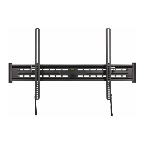
TV WALL MOUNT
WITH HEIGHT ADJUST
ITEM #1143421
MODEL #UT175TP
Español p. 15
Advertisement
Table of Contents

Summary of Contents for Utilitech UT175TP
- Page 1 ITEM #1143421 TV WALL MOUNT WITH HEIGHT ADJUST MODEL #UT175TP Español p. 15 ATTACH YOUR RECEIPT HERE Serial Number Purchase Date Questions, problems, missing parts? Before returning to your retailer, call our customer service department at 1-602-674-1000, 8 a.m. - 5 p.m., MST, Monday - Friday.
-
Page 2: Package Contents
PACKAGE CONTENTS PART DESCRIPTION QUANTITY PART DESCRIPTION QUANTITY Wall plate Right vertical rail Bubble level Tilt lever Left vertical rail Spring lock... - Page 3 HARDWARE CONTENTS (shown actual size) M4 x 12 M5 x 12 M6 x 15 M8 x 15 Screw Screw Screw Screw Qty. 4 Qty. 4 Qty. 4 Qty. 4 8 mm Lag bolt Anchor Qty. 4 Qty. 4 M4 x 30 M5 x 30 M6 x 30 M8 x 30...
-
Page 4: Safety Information
SAFETY INFORMATION Please read and understand this entire manual before attempting to assemble, operate or install the product. WARNING • FAILURE TO READ, THOROUGHLY UNDERSTAND, AND FOLLOW ALL INSTRUCTIONS CAN RESULT IN SERIOUS PERSONAL INJURY, DAMAGE TO PERSONAL PROPERTY, OR VOIDING OF FACTORY WARRANTY. - Page 5 ASSEMBLY INSTRUCTIONS 1a. For flat back flat panel: Attach left vertical rail (C) with two square washers (KK) and two screws (*). Repeat for right vertical rail (D). * Note: Rails can be attached with M4 x 12 screws (AA), M5 x 12 screws (BB), M6 x 15 screws (CC), or M8 x 15 screws (DD) depending on your TV.
- Page 6 ASSEMBLY INSTRUCTIONS 1b. For curved back flat panel: Secure vertical rail (C) with four spacers (*), two square washers (KK), and two screws (**). Repeat for vertical rail (D). * Note: 5 mm spacer (LL) or 10 mm spacer (MM) can be used depending on your TV.
- Page 7 ASSEMBLY INSTRUCTIONS 2. If screws are too long, additional 5 mm spacers (LL), 10 mm spacers (MM), and steel washers (NN) may be needed. Hardware Used 5 mm Spacer 10 mm Spacer Steel washer Wood Stud Installation Note: For concrete, proceed to step 7. 3.
- Page 8 ASSEMBLY INSTRUCTIONS 4. Use wall plate (A) to mark four mounting hole locations. Note: Use bubble level (B) to level wall plate (A). 5. Drill four 7/32 in. pilot holes 2-1/3 in. (60 mm) deep at the marked locations for the mounting holes.
- Page 9 ASSEMBLY INSTRUCTIONS Concrete Installation 7. Use wall plate (A) to mark four mounting hole locations. Note: Use bubble level (B) to level wall plate (A). 8. Drill four 3/8 in. pilot holes 2-3/4 in. (70 mm) deep at the marked locations for the mounting holes.
- Page 10 ASSEMBLY INSTRUCTIONS 10. Mount wall plate (A) using four steel washers (NN) and four 8 mm lag bolts (II) with a 1/2 in. socket wrench (not included). Hardware Used 8 mm Lag bolt Steel washer Final Installation 11. Hang right vertical rail (C) and left vertical rail (D) onto wall plate (A).
- Page 11 ASSEMBLY INSTRUCTIONS 13. To adjust tilt, loosen both tilt levers (E) and move panel to desired position. Tighten both tilt levers (E) to hold desired tilt. -3°–12° Note: For clarity, illustration is shown with panel removed. 5 mm 1/2 in. Additional Security (Optional) 14.
- Page 12 ASSEMBLY INSTRUCTIONS Leveling 1. Adjust the screws on the vertical rails to level the flat panel. 2. Use the built in level to gauge the adjustment. Note: bubble in level will be centered when correct. Lowes.com...
-
Page 13: Warranty
WARRANTY This product is covered against defects in materials and workmanship for 5 years. The manufacturer will repair or replace the defective component or product, at its sole discretion. Failure to follow product care instructions from the manufacturer will void the warranty. To obtain warranty service, contact customer service at 1-602-674-1000. - Page 14 Printed in China Lowes.com...
- Page 15 ARTÍCULO #1143421 SISTEMA DE MONTAJE DE TELEVISOR PARA PARED CON AJUSTE DE ALTURA MODELO #UT175TP ADJUNTE SU RECIBO AQUÍ Número de serie Fecha de compra ¿Preguntas, problemas, piezas faltantes? Antes de volver a la tienda, llame a nuestro Departamento de Servicio al Cliente al 1-602-674-1000, de lunes a viernes de 8 a.m. a...
-
Page 16: Contenido Del Paquete
CONTENIDO DEL PAQUETE PIEZA DESCRIPCIÓN CANTIDAD PIEZA DESCRIPCIÓN CANTIDAD Placa para pared Riel vertical derecho Nivel de burbuja Palanca inclinable Riel vertical izquierdo Resorte de bloqueo... - Page 17 ADITAMENTOS (se muestran en tamaño real) Tornillo Tornillo Tornillo Tornillo M4 x 12 M5 x 12 M6 x 15 M8 x 15 Cant. 4 Cant. 4 Cant. 4 Cant. 4 Tirafondo de 8 mm Ancla de Cant. 4 expansión Cant. 4 Tornillo Tornillo Tornillo...
-
Page 18: Información De Seguridad
INFORMACIÓN DE SEGURIDAD Lea y comprenda completamente este manual antes de intentar ensamblar, usar o instalar el producto. ADVERTENCIA • ASEGÚRESE DE LEER, COMPRENDER Y SEGUIR LAS INSTRUCCIONES ADECUADAMENTE; DE LO CONTRARIO, PUEDEN OCASIONARSE LESIONES PERSONALES GRAVES, DAÑOS A LA PROPIEDAD O ANULACIÓN DE LA GARANTÍA DE FÁBRICA. •... -
Page 19: Instrucciones De Ensamblaje
INSTRUCCIONES DE ENSAMBLAJE 1a. Para un panel plano posterior: adhiera el riel vertical izquierdo (C) con dos arandelas cuadradas (KK) y dos tornillos (*). Repita el procedimiento para el riel vertical derecho (D). * Nota: los rieles pueden adherirse con tornillos M4 x 12 (AA), M5 x 12 (BB), M6 x 15 (CC) o M8 x 15 (DD), según el televisor. - Page 20 INSTRUCCIONES DE ENSAMBLAJE 1b. Para un panel plano curvo posterior: asegure el riel vertical (C) con cuatro espaciadores (*), dos arandelas cuadradas (KK) y dos tornillos (**). Repita el procedimiento para el riel vertical (D). * Nota: el espaciador de 5 mm (LL) o el espaciador de 10 mm (MM) se pueden usar según el televisor.
- Page 21 INSTRUCCIONES DE ENSAMBLAJE 2. Si los tornillos son demasiado largos, podrían ser necesarios más espaciadores de 5 mm (LL), espaciadores de 10 mm (MM) y arandelas de acero (NN). Televisor Televisor Aditamentos utilizados Espaciador de 5 mm Espaciador de 10 mm Arandela de acero Instalación en vigas de madera Nota: para paredes de concreto, continúe con el...
- Page 22 INSTRUCCIONES DE ENSAMBLAJE 4. Utilice una placa para pared (A) para marcar las ubicaciones de los cuatro orificios de montaje. Nota: utilice un nivel de burbuja (B) para nivelar la placa para pared (A). 5. Taladre cuatro orificios guía de 7/32 pulg. con 2-1/3 pulg.
- Page 23 INSTRUCCIONES DE ENSAMBLAJE Instalación en pared de concreto 7. Utilice una placa para pared (A) para marcar las ubicaciones de los cuatro orificios de montaje. Nota: utilice un nivel de burbuja (B) para nivelar la placa para pared (A). 8. Taladre cuatro orificios guía de 3/8 pulg. con 2-3/4 pulg.
- Page 24 INSTRUCCIONES DE ENSAMBLAJE 10. Monte la placa para pared (A) con cuatro arandelas de acero (NN) y cuatro tirafondos de 8 mm (II) con una llave de dados de 1/2 pulg. (no se incluye). Aditamentos utilizados Tirafondo de 8 mm Arandela de acero Instalación final 11.
- Page 25 INSTRUCCIONES DE ENSAMBLAJE 13. Para ajustar la inclinación, afloje las palancas de inclinación (E) y mueva el panel a la posición deseada. Apriete las palancas de -3°–12° inclinación (E) para mantener la inclinación deseada. Nota: para obtener una explicación más clara, vea la ilustración del panel retirado.
- Page 26 INSTRUCCIONES DE ENSAMBLAJE Nivelación 1. Ajuste los tornillos en los rieles verticales para nivelar el panel plano. 2. Use el nivel integrado para medir el ajuste. Nota: la burbuja en el nivel estará en el centro cuando sea correcto. Lowes.com...
- Page 27 GARANTÍA Este producto tiene garantía contra defectos en los materiales y mano de obra por 5 años. El fabricante reparará o reemplazará el componente o producto defectuoso según su criterio. El incumplimiento de las instrucciones del fabricante acerca del cuidado del producto anulará la garantía.
- Page 28 Impreso en China Lowes.com...
Need help?
Do you have a question about the UT175TP and is the answer not in the manual?
Questions and answers