Table of Contents
Advertisement
Opera on Manual
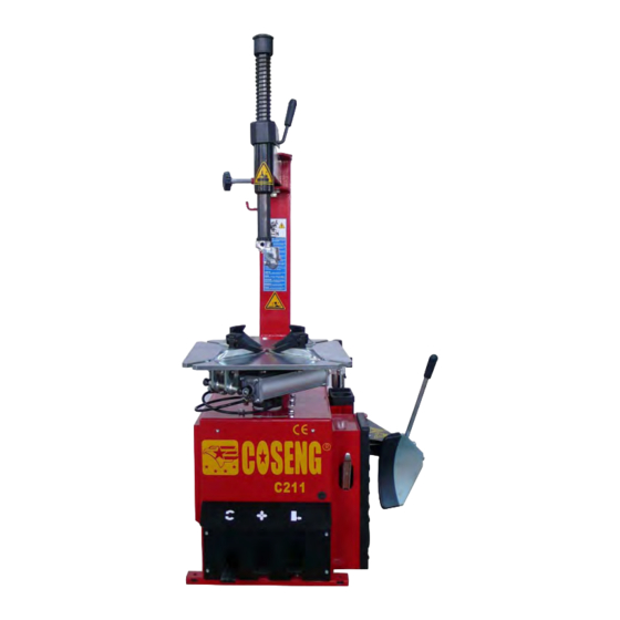
C211 C
Swing Arm Tire Changer
You will need the manual for the in-
formation of the machine, such as
safety warnings and precautions, as-
sembly, operating, maintenance and
parts lists/assembly diagrams. Keep
your invoice with this manual for fu-
ture reference. Manufacturer shall
not be liable for any injury to persons
on damage to things caused by fail-
ure to comply with these regulations
and can cancel warranty coverage.
Installation, Operation, Maintance
Advertisement
Table of Contents

Subscribe to Our Youtube Channel
Summary of Contents for Coseng C211 C
- Page 1 Opera on Manual C211 C Swing Arm Tire Changer You will need the manual for the in- formation of the machine, such as safety warnings and precautions, as- sembly, operating, maintenance and parts lists/assembly diagrams. Keep your invoice with this manual for fu- ture reference.
-
Page 2: Table Of Contents
TIRE CHANGER INSTRUCTION MANUAL INDEX INDEX PAGE 1. Technical Data ----------------------------------------------------------------- 2. General safety warnings and precautions --------------------------------- 3. Specific Product Warnings And Precautions --------------------------------- 4. Assembly Instruction ------------------------------------------------------------ 4-1 Transport 4-2 Unpacking 4-3 Product Description 4-4 Workplace Requirements 4-5 Assembly Procedure 4-6 Pneumatic Link Up 4-7 Electric Link Up 5. -
Page 3: Technical Data
1. TECHNICAL DATA DESCRIPTION Model □A □B □C Electric Requirements See the manufacturer’s serial plate Max. Wheel Diameter 39″(990mm) 40″(1016mm) 47″(1193mm) Max. Wheel Width 13″(330mm) 14″(355mm) 15″(381mm) 10″~18″ 10″~21″ 10″~24″ Outside Clamping – Rim Sizes Inside Clamping – Rim Sizes 12″~20″... -
Page 4: Specific Product Warnings And Precautions
5) STORE IDLE EQUIPMENT. When not in use, tools and equipments should be stored in a dry location to inhibit rust. If the machine has to be stored for a long time, disconnect it from all power sources. 6) DRESS SAFELY. Do not wear loose clothing or jewelry as they can become caught in moving parts. -
Page 5: Assembly Instruction
4.ASSEMBLY INSTRUCTION Fig.1 4-1 Transport When transporting the machine it must be handle with a forklift truck with the forks Positioned as show as in the Fig.1. 4-2 Unpacking When unpacking, check to make sure all parts shown on the spare parts List/Assembly. Diagrams are included. -
Page 6: Workplace Requirements
4-4 Workplace Requirements The machine’s workplace(not include assistant arm) requires 1400(width)×1685(depth) with at least 500 mm of clear space from each wall. Place the tire changer on a firm, smooth and unbroken floor. Drill four holes in the floor corresponding to the holes pre-drilled in the base of the machine. -
Page 7: Warning Label
5. WARNING LABEL CJ001: Unplug the power supply cable before carrying out maintenance work on the machine. CJ002: Danger: Electric voltage present. CJ003: When clamping a tire, never have your hands under the tire. CJ004: Danger: Compressed air cylinder inside. CJ005: Do not place your hands on the wheel;... -
Page 8: Operating Instructions
6.OPERATING INSTRUCTION 6-1 To Preliminary Operating Tests 1) Connect the tire changer to its air and electrical supply sources, and allow adequate time for the compressed air system to reach the recommended 110-PSI. 2) Depress the Reverse Pedal (3,Fig2) down, the turntable should turn in a clockwise direction. - Page 9 Place the wheel on the four jaws and, while keeping the wheel rim pressed down, depress the jaw clamp pedal as far as it will go. Check to make sure the wheel firmly secured by the jaws. Inside Clamping: Position the four jaws so that they are completely closed. Place the wheel on the four jaws and depress the jaw clamp pedal to open the jaws, thereby locking the wheel rim in place.
- Page 10 Fig.7 5) Move the tire so that the bead passes below the front section of the mounting head and is brought up against the edge of the rear section of the mounting head. (Fig.7) 6) Keep the tire bead pressed down into the wheel rim channel with your hands. Then, depress the reverse pedal to rotate the turntable clockwise.
-
Page 11: Frl Instruction
continue the inflation procedure with the wheel inside a special protection cage ( commercially available). NEVER exceed the maximum inflation pressure given by the tire manufacturer. 3) ALWAYS keep hands and entire body back from inflating tire. ONLY specially trained personnel are allowed to perform these operations. Do not allow other to operate or be near the tire changer 7. -
Page 12: Routine Maintenance
This is oil indicator that the oil dropping quantity should Check the oil level in the lubricator once be checked once a day. Make sure that one drop of oil a day. If necessary, remove the oil cap. is injected into the tank every 3-4 times the Bead Fill the tank with 50W hydraulic oil, and Breaker Pedal is depressed. -
Page 13: Trouble Shooting Guide
Fig 10 8) To clean or replace the center chuck value, remove the side cover, which is located on the left side of the body assembly, by unscrewing the six screws. 9) Remove the air hoses from the center chuck valve. 10) Clean the center chuck valve, using a jet of compressed air. - Page 14 Turntable locks while mounting/removing tire. B) Reas. Belt loose. C) Disp. Adjust belt tension. A) Situ. Jaws slow to open/close. B) Reas. Silencer clogged. C) Disp. Clean or replace silencer. A) Situ. Turntable does not lock the wheel rim correctly. B) Reas.
-
Page 15: Mounting Head's Angle Adjusting
10. Mounting Head’s Angle Adjusting The mounting head standard position Fig. 12 The following case is not correct: The angle setting of this mounting head for shipment is set to fit for rim size 12” to 18”. In case application of rim size over this range, appropriate adjustment to the angle of the mounting head or special mounting head replacement is needed. -
Page 16: Exploded Drawings And Spare Parts List
!%&&'($ )* +#,,%(& -1."" 2% .2)#& "#$ / #3... - Page 17 " " " +,,-. /0 1 22+., 345 6+ 56/ , $% % & " " "...
- Page 18 $%%&'# () *"++$'% ,1-!! 2$ -2("% !"# "3...
- Page 19 " & & & & & & & & " " " & & & & &...
- Page 20 & & & & & & "% " " "( "# " " $ " +- + " $ " " . " $ " $...
- Page 24 Notice !! If Machine is IP or IT version, this 4 IN 1 inflation gun will not be included.
- Page 25 SPARE PART LIST Part Code Part Name Code Part Name C2110101 Body GB/T 95 Washer Φ12 C2110615 Front cover GB/T 95 Flat spacer for chuck GB/T 70 Screw M5×10 C2880125 Washer for square turntable GB/T 70 Screw M6×35 GB/T 894 Circlip φ65 GB/T 93 Washer φ6...
- Page 26 C211011201 Reverse pedal C211011213 Twist-spring C211015203 Upper cover GB/T 95 placket pin GB/T 1096 Key 10×40 C211011205 Connecting spindle GB/T 1096 Key 14×40 C211011206 Connecting sheath JB1092 O-ring φ34 C211011207 Switch lever C211015205 Plastic cap GB/T 845 Self tapping screw ST3×8 GB/T 1337 Self-locking nut M8 C211011215...
- Page 27 IT VERSION If the machine’s version is with IT set, there is an inflating pedal on the left side of the machine. When the pedal is pushed down to its middle position, air is released from the airline gauge. When the pedal is pushed down completely, air is released from the inflation gauge along with powerful jet from the nozzles on the turntable clamps.
- Page 28 -2 Bead seating and inflating NOTE: A WHEEL CAN EXPLODE IF: 1) The diameter of the rim is not exactly the same at the tire’s. 2) The rim or tire are defective. 3) If the recommended pressure is exceeded during bead seating. 4) The tire is inflated to a pressure higher than the maximum recommended by the manufacturer.
- Page 30 IT Spare Part List Part code Part Name Part code Part Name C211016504 I2110301 Tank IT39 T Union I2330340 PQ-L10 safety valve IT40 Air manometer Hose I2330341 (tank to quick exhaust valve) IT41 GB/T5781 Screw M5 Hose C2110165 I2110312 (input to quick exhaust valve) IT42 Tools box MOV-03A...
Need help?
Do you have a question about the C211 C and is the answer not in the manual?
Questions and answers