Table of Contents
Advertisement
Quick Links
Advertisement
Table of Contents

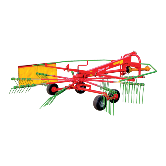
Summary of Contents for Mesko-Rol Z 548
-
Page 2: Table Of Contents
CONTENTS DECLARATION OF CONFORMITY ……….……………………………………..1. INTRODUCTION ……………………………..………………………………………. 2. APPROPRIATE USE OF THE MACHINE .……............3. SAFETY INSTRUCTIONS ……………………………………………......3.1. General safety principles….…………………………........3.2. Detailed safety principles ………………………..........3.2.1. Preparation for work…………………………………………....3.2.2. Transporting ………………………………………………....3.2.3. Working ……………………………………………………………..3.2.4. Uncoupling from the tractor for parking or storage …......3.2.5. - Page 3 Safety sign and hazard pictorials. General principles. This declaration expires if the machine is modified or changed without the manufacturer's written consent. Skarżysko - Kamienna 07-01- 2015 Jacek Kowalski President of the Board of MESKO-ROL...
-
Page 4: Introduction
The identification details for the machine are provided on the name plate attached to the frame. We recommend using original spare parts from MESKO-ROL as this will maximize the lifetime of your machine. CAUTION! If you have any doubts or if anything contained herein is unclear, please contact your... -
Page 5: General Safety Principles
3. SAFETY OF USE IMPORTANT NOTICE WARNING This warning symbol indicates an important notice concerning risks. Wherever you encounter this symbol in this manual, read the accompanying notice and exercise caution. 3.1. GENERAL SAFETY PRINCIPLES BE CAREFUL. READ THIS MANUAL CAREFULLY TO AVOID EXPOSING YOURSELF AND OTHERS TO RISK FOLLOW all the safety rules and take precautions applicable to the machine and its operation. -
Page 6: Detailed Safety Principles
3.2. DETAILED SAFETY PRINCIPLES 3.2.1. PREPARATION FOR WORK READ this manual carefully. Make sure that you understand all the safety rules and operating instructions pertaining to the preparation for operation, towing and storage. The manufacturer shall not be liable for any consequences of your neglect of these rules and instructions. -
Page 7: Transporting
BEFORE LIFTING the rake, check that there are no bystanders or animals within the reach of the rake. THE RAKE may be started up only after correct setting of all its components. Do not start the rake while it is adjusted for the towing on public roads! ... -
Page 8: Working
FOR THE PURPOSES OF TOWING lock the rake with the latch to limit its movements to the left and right. WHILE DRIVING consider the large size of the machine. 3.2.3. WORKING BEFORE CONVERTING the rake from transport position to operation position shut down the engine, remove the key from the ignition switch and immobilise the tractor. -
Page 9: Technical Maintenance
Monitor the parts for wear and damage and, if required, replace them early enough with new original parts manufactured by Z 548, because only these will provide the desirable result. 3.2.6. SAFETY SIGNS The rake has warning labels with safety icons applied at the points shown in Fig. 1. They contain clear notices and tips about what you should be particularly careful about to stay safe. - Page 10 List of warning and notice labels placed on the rake Read this manual before starting your work. Shut down the tractor’s engine and remove the key from the ignition switch before proceeding to maintenance or service. Risk from hard objects ejected by the machine. Keep safe clearance.
- Page 11 Fig. 1 Location of warning labels on the rake...
-
Page 12: Risks
3.2.7. RISKS CAUTION! The rake is a dangerous machine. It may be operated only by a person who has carefully read and understood this manual. Do not allow children to operate the rake. Never allow children to play with, or near, the rake even if it is idle or stored. 3.2.8. - Page 13 WARNING! Drive the rake only with a telescopic articulated shaft with an overload-proof coupling (we recommend 4R-302-3-BA-P4B1 by SIPMA based in Lublin, Poland). Noise and vibration While working, the operator sits in the tractor’s cabin. The acoustic pressure level (LpA) measured as specified in the PN-EN ISO 4254-1:2006 standard, appendix B, p.
-
Page 14: Adjustments And Settings
żółta nalepka niebieska nalepka Fig. 2a 1 - Rake gearbox, 2 - Main frame, 3 - 3-point linkage frame, 4 - Suspension frame, 5 - Wheel arm, 7 - Adjusting screw with the hand crank, 8 - Connecting arm, 9 - End arm, 10 - Tines, 12 - Central beam; set, 13 - Safeguard bow, 14 - Swath curtain, 15 - Swath curtain arm. -
Page 15: Setting Of Tine Arms And Swath Curtain In Working And Transport
- firmness of soil and root system, - volume of crop and its moisture content. Fig. 3 6 - Support wheel, 7 - Adjusting screw with hand crank, 10 - Tines, 16 – Central hitch of the 3-point linkage system. The user must perform the correct setting of the height of tines in order to: - obtain good raking of crop, - avoid the devastation of the top layer of the soil and root system and contamination of the crop. - Page 16 END ARMS AND THE SWATH CURTAIN IN WORKING POSITION In working position the end arm and the swath curtain should be set as per fig. 5. Fig. 5 8 - Connecting arm, 9 - End arm, 10 - Tines, 11 - Linchpin; set, 12 - Central beam;...
- Page 17 END ARMS AND THE SWATH CURTAIN IN TRANSPORT POSITION Fig. 6 2 - Main frame, 9 - End arm, 10 - Tines, 11 - Linchpin; set. 12 - Central beam; set, 14 - Swath curtain,...
-
Page 18: Positions
15 - Swath curtain arm, 16 - Side arm, 4.2.3. SETTING THE SAFEGUARD BOWS IN WORKING AND TRANSPORT POSITIONS SAFEGUARD BOWS IN WORKING POSITION Fig. 7 2 - Main frame, 12 - Central beam; set, 13 - Safeguard bows, 30 - Linchpin with safety pin... - Page 19 SAFEGUARD BOWS IN TRANSPORT POSITION Fig. 8 13 - Safeguard bows After setting safeguard bows into transport or working position always secure them using linchpin with safety pin (fig. 7. and fig. 8. - item 30).
-
Page 20: The Latch In Transport Position
4.2.4. SETTING THE LATCH IN WORKING AND TRANSPORT POSITION Fig.9 The latch in working position. Fig. 10 The latch in transport position. 3 - 3-point linkage frame, 18 - Latch, 19 - Safety pin Setting the latch 18 in working position is shown in fig. 9. In this state rake can make limited movements to left and right against the tractor. -
Page 21: Setting The Rake's Height For Transport
It is necessary to lock the latch 18 with safety pin 19 every time, to avoid disengaging the latch from the 3-point linkage frame. 4.2.5. SETTING THE RAKE'S HEIGHT FOR TRANSPORT Fig. 11 20 - Portable warning lights, 21 - Red reflective lights. Lift the rake on the tractor to the transport position (fig. -
Page 22: Setting The Support Leg
4.2.6. SETTING THE SUPPORT LEG Set the support leg 22 using the safety pin 23 for: transport and operation in upper position as per fig. 12. parking in lower position as per fig. 13. Fig. 12 3 - Main beam, 22 - Support leg, 23 - Safety pin... - Page 23 Fig. 13 3 - Main beam, 22 - Support leg, 23 - Safety pin...
-
Page 24: Installation Of Portable Warning Lights And Warning Triangle
4.2.7. INSTALLATION OF PORTABLE WARNING LIGHTS AND WARNING TRIANGLE Fig. 14 12 - Central beam; set, 20 - portable warning lights, 24 - Warning triangle 25 - Plug. Install portable warning lights 20 and warning triangle 24 as per fig .14. Plug the plug 25 into the tractor's power supply socket. -
Page 25: Preparation For Transport
4.3. PREPARATION FOR TRANSPORT 1. Set end arms 9 as per fig. 6. 2. Set the swath curtain arm 14 as per fig. 6. 3. Set safeguard bows 13 as per fig. 8. 4. 4. Set 3-point linkage frame catch pins according to tractor's three point linkage system category I or II as per fig. -
Page 26: Towing The Rake
Spacing between the 3-point linkage frame lower catch pins. 26 - lower catches 4.3.1. TOWING THE RAKE Pay attention to the correct operation of portable warning lights. Exercise caution while towing due to the size of the rake. 4.4. PREPARATION FOR OPERATION Before putting the rake into operation always make sure that there are no people or animals within the working range of raking arms. -
Page 27: Operation Of The Rake
4.4.1. OPERATION OF THE RAKE Before putting the rake into operation and during operation always make sure that there are no people or animals within the working range of raking arms. 1. Properly set machine will rake from the field lane located under tines which are in raking position acc. - Page 28 2. Incorrect setting of the rake caused by: tines set too high above the field surface results in leaving unraked crop along the entire working width fig.17. Fig. 17 The central hatch of the three point linkage system set too short results in leaving unraked crop on the edges of the working width fig.18.
- Page 29 Fig. 18 the central hatch of the three point linkage system set too long results in leaving unraked crop in the middle of the working width fig.19.
-
Page 30: Preparation For Parking And Uncoupling From The Tractor
Fig. 19 4.5. PREPARATION FOR PARKING AND UNCOUPLING FROM THE TRACTOR Be careful while uncoupling the rake from the tractor. 1. The rake can be parked in transport position or in working position. 2. Position the rake with tractor's three point linkage system at the minimum height above the ground. -
Page 31: Repairs
6. When required, replace worn parts with new original parts offered by the manufacturer of the Z 548 rake. Only original parts will provide the desirable result. While purchasing spare parts and tines ensure the parts come from the manufacturer of the Z548 rake. -
Page 32: Specifications
5. SPECIFICATIONS 1. Overall dimensions for parking and towing: - Length 3 300 mm - Width 2 150 mm - Height 2 050 mm Overall dimensions for operation: - Length 3 960 mm - Width 3 780 mm - Height 1 300 mm 2. -
Page 33: Optional Accessories
7. OPTIONAL ACCESSORIES Copy wheel ZK 910.00.00 for rotary rake Z 548 To avoid damage to the turf on very uneven ground and to collect swath thoroughly you can mount the copy wheel to the 3-point linkage frame, as an accessory. - Page 34 Copy wheel height adjustment You can adjust copy wheel height by putting the linchpin (set, item 5, page 50) into the openings in the copy wheel unit (item 5, page 50). Secure the linchpin with the safety pin (item 13, page 50).
-
Page 35: Spare Parts List
8. SPARE PARTS LIST While ordering a part, specify its name, part number, the rake’s year of manufacture and its number. - Page 37 Main frame, set ZK-100.00.00. Manufacturer’s number Part/assembly name Qty. Remarks ZK-111.00.00 Intermediate frame, welded ZK-12.00.00 Latch, set ZK-150.00.00 3-point linkage frame, welded HS 0200 Support leg HS 0188 Lower catch, set HK 0028V Mandrel, set GZ 0281V Bolt, set GZ 283 Bolt ZK-14.00.00 Linchpin, set...
- Page 39 Jackshaft ZK-200.00.00. Manufacturer’s Part/assembly name Qty. Remarks number ZK-20.00.02 Shaft guard PN-70/M-85005 Parallel key 8x7x55 PN-88/M-82176 Nut P M14-8-B-Fe/Zn8cC PN-85/M-82105 Screw M14x45-8.8-B-Fe/Zn8cC PN-85/M-82105 Screw M6x16-8.8-B-Fe/Zn8cC ZK 200.20.00 Welded bush ZK 200.10.10 Quill shaft UCF 207 Bearing unit PN-89/M-85023 Spring-type straight pin 6x50 4R-302-3-BA-P4B1 Telescopic articulated shaft ZK 200.10.01...
- Page 41 Tine arms ZK–30.00.00. Manufacturer’s Part/assembly name Qty. Remarks number ZK-300.10.00 Connecting arm PN-85/M-82101 Screw M12x60-8.8-A-Fe/Zn9cC ZK-30.30.00 Linchpin, set. ZK-30.20.01-3 End arm ZK-30.20.02-7 Tine ZK-30.20.03-4 Shackle ZK-30.20.04-1 Strap PN-85/M-82101 Screw M10x60-8.8-A-Fe/Zn8cC PN-88/M-82176 Nut PM10-8-A-Fe/Zn8cC PN-88/M-82176 Nut PM12-8-A-Fe/Zn8cC PN-89/M-85023 Spring-type straight pin 12 x 45...
- Page 43 Beam and safety bows system ZK-500.00.00 Manufacturer’s number Part/assembly name Qty. Remarks ZK-50.60.00 Central beam, set ZK-50.80.00 Swath curtain arm, set ZK-50.30.10 Apron ZK-50.30.01 Angle bar ZK-50.30.02 Stiffener plate PN-85/M-82105 Screw M6x16-8.8-A-Fe/Zn8cC PN-79/M-82019 Washer A6.6-Fe/Zn9cC PN-88/M-82176 Nut PM6-A-Fe/Zn8cC PN-85/M-82105 Screw M8x20-8.8-A-Fe/Zn8cC 10.
- Page 45 Wheel system ZK-60.00.00. Manufacturer’s Part/assembly name Qty. Remarks number ZK 60.10.00 Suspension frame PN-77/M-82105 Screw M8x20-8.8-A-Fe/Zn8cC ZK-00.00.06 Parallel key A10x8x110 PN-85/M-82101 Screw M-12x100-8.8-A-/Zn8cC PN-88/M-82176 Nut PM12-8-A-Fe/Zn8cC ZK-60.00.02 Joint block ZK-60.20.00 Adjusting screw, set ZK-60.00.06 Plate Gearbox K-791A Comer gearbox 150-01.100.APT Starosielski gearbox ZK-60.41.00 Main frame...
- Page 47 Tandem unit ZK 900.00.00 (Tandem version) Manufacturer’s number Part/assembly name Qty. Remarks ZK 700.00.00 Left tandem ZK 800.00.00 Right tandem ZK 700.10.00 Left beam, welded ZK 800.10.00 Right beam, welded SF-10W26 Slide washer ZK 700.00.02 Washer SF-10-25-30 Slide bush PN-85/M-82105 Screw M12x25-8.8-B-Fe/Zn8cC PN-83/M-82037 Washer 13 Fe/Zn8cC...
- Page 49 Copy wheel ZK 910.00.00 (optional accessory) Manufacturer’s number Part/assembly name Qty. Remarks 1. ZK 150.10.00 Latch, welded 2. ZK 150.20.01 Bolt 3. ZK 150.10.03 Left arm 4. PN-88/M-82176 Nut P M10-8-B-Fe/Zn8cC 5. ND 9734V Node chain 6. PZ 25V Linchpin 7.
- Page 51 Copy wheel ZK 910.00.00 (optional accessory) Manufacturer’s number Part/assembly name Qty. Remarks 1. NP 0482 Square plug 35x35 2. 0656 4448 Cord 3. ZK 910.00.02 Clamp 4. ZK 910.20.00 Fixing unit 5. ZK 910.40.00 Linchpin, set. 6. ZK 910.00.01 Washer 7.
- Page 52 Notes...
Need help?
Do you have a question about the Z 548 and is the answer not in the manual?
Questions and answers