Table of Contents
Advertisement
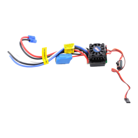
Xcelorin Brushless Electronic Speed Control
Thank you for purchasing the Losi™ Xcelorin™ Electronic Speed Control (ESC).
This ESC will provide you the benefit of the latest in brushless technology.
Featuring an advanced software interface with which you can finely tune the
feel of the ESC to your needs, or use the Advanced Quick Programming Card
(AAQPC) to make adjustments.
We believe it will be to your benefit to take the time and effort to read this
manual.
We are confident you will be satisfied with the performance of the Xcelorin
Sensorless ESC.
Losi/Horizon Support
If you have any questions concerning setup or operation of your Xcelorin ESC,
please call Horizon customer support at 1 877-504-0233
You are welcome to call us with any support issue or question you may have.
LOSB9515 Xcelorin Electronic Speed Control v1.1
Page 1
Advertisement
Table of Contents

Summary of Contents for Team Losi Xcelorin LOSB9515
- Page 1 Xcelorin Brushless Electronic Speed Control Thank you for purchasing the Losi™ Xcelorin™ Electronic Speed Control (ESC). This ESC will provide you the benefit of the latest in brushless technology. Featuring an advanced software interface with which you can finely tune the feel of the ESC to your needs, or use the Advanced Quick Programming Card (AAQPC) to make adjustments.
-
Page 2: Table Of Contents
Table of Contents Overview ..................3 Profile Overview ................5 Initial Profile setting from the Factory...........6 Overriding the Active Profile..............7 Selecting profiles................8 Modifying the ACTIVE profile ...............10 Using the Quick Programming Card ............12 Setup / Calibration to Transmitter............13 Confirmation of Full Throttle and Brake..........15 Connect the Xcelorin ESC and Sensorless Motor ........16 Connecting the Xcelorin ESC to your Receiver ........17 Xcelorin Software Installation ..............18... -
Page 3: Overview
Overview The Losi Xcelorin electronic speed control (ESC) is specifically designed for operating Sensorless brushless motors. Featuring low on-resistance, enhanced throttle response and strong brakes, this ESC has enough features to satisfy the most demanding driver. The pre-installed high airflow fan attached to the ESC heat sinks keep it cool and performing to the peak of its ability. - Page 4 A key feature is the three (3) stored settings within the ESC that are easily recalled for convenient use. These stored settings are referred to as “profiles.” These do not limit the functions of the ESC as you can easily use the included Advanced Quick Programming Card (AQPC) to make changes to any desired setting.
-
Page 5: Profile Overview
Profile Overview These stored settings, also referred to as “profiles,” are defined as follows: Profile #1 - “High Speed Performance” Cutoff Voltage- LiPo 3S Brake/Reverse Role- Forward only Motor Timing- Normal Initial Acceleration- High ** Drag Brake- 25% Brake- 40% Throttle Limit –... -
Page 6: Initial Profile Setting From The Factory
Profile #3 settings (Default) “Low Speed - Beginner” Cutoff Voltage- No Cutoff (NiMH) Brake/Reverse Role- Forward with pause then Reverse Motor Timing- Low Initial Acceleration- Low ** Drag Brake- 40% Brake- 60% Throttle Limit – 60% of Full Throttle Reverse Throttle Limit – 30% ** AQPC cannot change NOTE: You must use the supplied Xcelorin Setup Software to access all features of the ESC. -
Page 7: Overriding The Active Profile
Braking Percent Percent Drag Brake Legacy or 2.4Ghz Legacy Neutral Deadband Reverse Rotation blank Throttle Profile Linear Brake Profile Linear Overriding the Active Profile There are three (3) saved profiles within the ESC that were previously described. To override a setting within the active profile, select a saved profile that resembles your needs, or make further changes to the current profile. -
Page 8: Selecting Profiles
Drag Brake – 40% Throttle Limit – 80% of Full Throttle (was 60%) Reverse Speed – 50% Motor Timing - Low Then follow the instructions for using the Quick Programming Card. You can change one setting at a time or any combination. Making the above change is ONLY overriding the active profile. - Page 9 Profile 1 Yellow and Blue LED flash Profile 2 Yellow, Blue and Green LED flash Profile 3 Yellow, Blue, Green and Red Flash (default setting) 6. To make a change, quickly press the setup button, which will advance you to the next profile.
-
Page 10: Modifying The Active Profile
Modifying the ACTIVE profile The Xcelorin Advanced Quick Programming Card (AQPC) is used to make all adjustments to the active profile in your ESC. Any ACTIVE profile can be modified. LOSB9515 Xcelorin Electronic Speed Control v1.1 Page 10... - Page 11 Using the Advanced AQPC, you can set the following: Cutoff Voltage Motor Timing • NiMH • Very Low 0° • 2S LiPo • Low 2° • 3S LiPo • Normal 4° • High 6° • Very High 8° Braking Strength Brake/Reverse Role •...
-
Page 12: Using The Quick Programming Card
Using the Quick Programming Card With the AQPC in your hand and the back facing you, notice the small jumper connectors. The jumpers are used to indicate which function you want to activate. To change the settings rearrange the small jumpers to the desired settings. To Upload to the ESC do the following: 1. -
Page 13: Setup / Calibration To Transmitter
7. Pay close attention to the ESC LEDs and you will notice the Red LED flash, and on the AQPC the Red LED will come on. If you do not notice the ESC Red LED flash, you can unplug the Signal wire from the AQPC and reconnect again to verify the operation of the Red LEDs. - Page 14 1. Turn on the transmitter. 2. While turning on the vehicle Press and Hold the setup button, notice the Yellow LED is now ON solid. When the Yellow LED is on solid, you can release the setup button. Note: If you cannot get the ESC to Calibrate, you may need to reverse your Throttle Servo on the transmitter.
-
Page 15: Confirmation Of Full Throttle And Brake
• After turning on the vehicle, the Blue LED will be on for normal operation. • If reverse is active then you will notice the Yellow LED is also on. Confirmation of Full Throttle and Brake • While the ESC is on and operational, if you pull the throttle trigger to Full Throttle the Green LED will turn ON solid. -
Page 16: Connect The Xcelorin Esc And Sensorless Motor
Connect the Xcelorin ESC and Sensorless Motor There are three wires from the ESC a Black, Blue and White for the motor. Below see an Xcelorin Sensorless Brushless motor with the Protection Cap removed for easy access and wire installation Each wire will be soldered to a single motor tab. -
Page 17: Connecting The Xcelorin Esc To Your Receiver
Connecting the Xcelorin ESC to your Receiver The Receiver wire will connect to nearly all current receivers. Plug it into the Throttle Channel of the receiver. Brown Negative Positive Orange Signal LOSB9515 Xcelorin Electronic Speed Control v1.1 Page 17... -
Page 18: Xcelorin Software Installation
Xcelorin Software Installation In the box along with your Electronic Speed Control, you will find: • Xcelorin Software CD • USB Cable • USB Adapter Requirements: • Windows Operating System preferably Windows XP or higher • USB Port to be available compatible with USB 1.0 or higher •... - Page 19 1. Now, insert the CD into your CD/DVD Player. The following should automatically display. LOSB9515 Xcelorin Electronic Speed Control v1.1 Page 19...
- Page 20 2. When ready select the Next button. If you wish to cancel, select the Exit button. If you do not get the previous panal, click on My Computer and then select (click on) the CD/DVD Drive to open it. You should then have a panel similar to the one below. Select and click on the Losi Setup.exe program icon.
- Page 21 3. The following should now be presented. You can change the default directory if desired, we recommend using this default. When ready select the Next button. If you wish to cancel, select the Exit button. LOSB9515 Xcelorin Electronic Speed Control v1.1 Page 21...
- Page 22 4. The following should now be displayed and confirms the install location. When ready, select the Start button. If you wish to cancel, select the Exit button. LOSB9515 Xcelorin Electronic Speed Control v1.1 Page 22...
- Page 23 5. The following panel should now be presented, and confirms install was successful. Select the Exit button to finish. LOSB9515 Xcelorin Electronic Speed Control v1.1 Page 23...
- Page 24 6. Connect the USB cable to your Windows PC or Laptop computer. 7. Connect the Xcelorin USB Adapter to the mini USB connector on the USB Cable. You will be prompted to install the device drivers, they are both unsigned so select OK and continue.
- Page 25 Notice in the Connection box the USB is Green and the ESC is still Red. 9. You are ready to connect the Adapter to the ESC, using the Signal Wire. WARNING: Disconnect the battery from the ESC before connecting the Xcelorin USB adapter to the speed control.
- Page 26 Please note the label on the USB Adaptor, there are 3 color bars each marked and indicating how to connect the Receiver wire to the adapter. 10. With the ESC connected to the USB Adapter, the Xcelorin Software Connection status icons should now both be GREEN. The Losi Xcelorin software is now installed and ready for use.
-
Page 27: Xcelorin Software Overview
Xcelorin Software Overview Using this you will find it quite easy to configure your new speed control. On the main panel, you will notice this button , if you click on this the specific help for that function will display. Take a moment to review the selectable functions, and read the specific help text for each to become familiar with them. - Page 28 General Tab: Here you will find the following configuration settings: Battery Type and Cutoff Voltage, Brake/Reverse, Motor Timing, Initial Acceleration, Percent Drag Brake, ESC operating mode, Dead band adjustment, Braking Percentage, Throttle Limit, Reverse Throttle Limit and Motor Rotation. All changes are done at your own risk. Throttle Tab: Only recommended for more experienced Electronic Speed Control users.You can remap the throttle profile from the default linear line.
- Page 29 Upgrade Firmware: Use of this button will begin the firmware upgrade process. The following pop up will be displayed, and you need to select the location of the firmware update file. You may cancel this process here without any effect to the ESC firmware. After finding and selecting the file, this confirmation screen will then display.
-
Page 30: Updating Esc Firmware
If you select OK, the progress status percentage of the upgrade will be displayed in the lower right. Please do not unplug your computer or the ESC while the upgrade is in progress or damage to the ESC may result. If no problems were encountered, OK will be displayed and the configuration redisplayed. - Page 31 C0101XX.LSC - 18 Xcelorin D0101XX.LSC - 10 Xcelorin Sensored E0101XX.LSC - 10 Xcelorin SensorLess F0101XX.LSC - Reserved G0101XX.LSC - Reserved Note: XX denotes the incremental release level General TAB information Battery Type –Select NiMH, or Lithium-Ion / Lithium Polymer batteries Cutoff Voltage –...
- Page 32 Following the above example for an 8-cell NiMH battery, you would select 5.0V and then increase 6 steps up to 5.6V. DO NOT USE the above setting with any type of Lithium battery pack When using any Lithium or M1 (A123) batteries, they must not be discharged to less than 3.0V per cell.
- Page 33 Throttle Limit – Use this to limit the power available using forward throttle. The lower the percent the less forward throttle speed will be available. (Default) • • 100% of forward speed 50% of forward speed • 90% of forward speed •...
- Page 34 Motor Timing - This option affects the power band and efficiency (run time) of an electric motor. The default is “Normal” and is a good starting point to deliver power and provide good run time. • Low Provides maximum efficiency with less power. Higher timing produces significantly more power but at the expense of efficiency (less run time) and typically the motor will generate more heat.
- Page 35 Initial Acceleration - Use this to limit the initial power that is sent to the motor when starting from a complete stop. Using the LOW option, the vehicle will launch very slowly and provide the longest run times. When using the HIGH choice, you will have wheel-spinning acceleration at the cost of run time.
- Page 36 Braking Percent - Gives you the ability to have full control over the amount of brake your vehicle will have. NOTE: Selecting the advanced function “BRAKE CURVE” and using this method to adjust the feel of the desired brake strength will override the “Braking Percent” parameter. •...
- Page 37 If you are running in dusty or slippery surfaces, you will more than likely want to use the lowest option. • • • • • 8% (Default) • • 10% • • 12% Legacy or 2.4GHz – This setting is intended to reflect what type of Radio System you are using, i.e.
- Page 38 • • 3 (Default) • • • Reverse Rotation – If you would like to change the direction of the motor without changing any wiring, then select or de-select this box. This will be useful for applications where removing the motor wiring is impractical or difficult.
- Page 39 Throttle TAB information Setting Throttle Profile – You can select either Linear (Default) or Curve. Using Curve will activate changes you may have made to the left for the throttle profile. Using the Left Mouse Button, you may click to select a point on the throttle line and drag it into the desired position.
- Page 40 Below is an example of a slow ramp up to full throttle versus the above linear graph LOSB9515 Xcelorin Electronic Speed Control v1.1 Page 40...
- Page 41 Below is an example of an accelerated ramp up to full throttle LOSB9515 Xcelorin Electronic Speed Control v1.1 Page 41...
- Page 42 Brake TAB information Setting Brake Profile – You can select either Linear (Default) or Curve. Using Curve will activate changes you may have made to the left for the throttle profile. Using the Left Mouse Button, you may click to select a point on the throttle line and drag it into the desired position.
- Page 43 Below is an example of a gradual increase in braking versus the above linear graph LOSB9515 Xcelorin Electronic Speed Control v1.1 Page 43...
- Page 44 Below is an example of increase of braking action then leveling to full brake LOSB9515 Xcelorin Electronic Speed Control v1.1 Page 44...
-
Page 45: Xcelorin Sensorless Brushless Esc Specifications
Xcelorin Sensorless Brushless ESC Specifications Type: Sensorless Brushless ONLY Cells w/BEC: 6-12 Cells (NiMH)/ 2S-3S (LiPo) Auto Cutoff: Programmable BEC Voltage: 6.1V, 3A Forward: Y Reverse: Y Brake: Y Continuous Maximum Current: 100A Momentary Peak Current: 540A Input Connector Types: Losi EC3 style Motor Limit: Most 540-sized sensorless motors of 8000Kv or less... -
Page 46: Xcelorin Replacement Parts
Xcelorin Replacement Parts LOSB9351 Heat sink 10th esc $12.99 LOSB9361 Plastic Replacement case 10th $5.99 LOSB9365 ESC Fan 30mm $19.99 LOSB9370 Capacitor 10th 8200mf $11.99 LOSB9376 Quick Program Interface Card for 18th/10th only $12.49 LOSB9380 Software CD, USB Cable/Connector $28.49 LOSB9377 Advance Quick Programming Card 18th/10th $12.49... -
Page 47: Warranty Period
Warranty Period Exclusive Warranty- Horizon Hobby, Inc., (Horizon) warranties that the Products purchased (the "Product") will be free from defects in materials and workmanship at the date of purchase by the Purchaser. Limited Warranty (a) This warranty is limited to the original Purchaser ("Purchaser") and is not transferable. - Page 48 Horizon to be defective. In the event of a defect, these are the Purchaser's exclusive remedies. Horizon reserves the right to inspect any and all equipment involved in a warranty claim. Repair or replacement decisions are at the sole discretion of Horizon. This warranty does not cover cosmetic damage or damage due to acts of God, accident, misuse, abuse, negligence, commercial use, or modification of or to any part of the Product.
- Page 49 Law: These Terms are governed by Illinois law (without regard to conflict of law principals). Safety Precautions: This is a sophisticated hobby Product and not a toy. It must be operated with caution and common sense and requires some basic mechanical ability. Failure to operate this Product in a safe and responsible manner could result in injury or damage to the Product or other property.
- Page 50 If this Product needs to be inspected or repaired, please call for a Return Merchandise Authorization (RMA). Pack the Product securely using a shipping carton. Please note that original boxes may be included, but are not designed to withstand the rigors of shipping without additional protection. Ship via a carrier that provides tracking and insurance for lost or damaged parcels, as Horizon is not responsible for merchandise until it arrives and is accepted at our facility.
- Page 51 Should your repair not be covered by warranty the repair will be completed and payment will be required without notification or estimate of the expense unless the expense exceeds 50% of the retail purchase cost. By submitting the item for repair you are agreeing to payment of the repair without notification.
- Page 52 Electronics and engines requiring inspection or repair should be shipped to the following address: Horizon Service Center 4105 Fieldstone Road Champaign, Illinois 61822 All other Products requiring warranty inspection or repair should be shipped to the following address: Horizon Product Support 4105 Fieldstone Road Champaign, Illinois 61822 Please call 877-504-0233 with any questions or concerns regarding...
Need help?
Do you have a question about the Xcelorin LOSB9515 and is the answer not in the manual?
Questions and answers