Advertisement
6205 Kestrel Road; Mississauga, Ontario; Canada; L5T 2A1
Phone: (905) 564-0801 Fax: (905) 564-0806 www.telecor.com
These servicing instructions are for use by qualified service personnel only. To reduce the risk
of electric shock, do not perform any servicing other than that contained in the operating
instructions unless you are qualified to do so.
The Telecor SI-125 Power Amplifier delivers 125 watts of audio power intended to drive
industry standard speakers for sound reinforcement and paging systems. The amplifier will
accept either a balanced or single-ended input source. A sensitivity Input Level switch is
provided to select either the 1 V (0 dB) or 100 mV (-20 dB) input level. Output terminals are
provided for 4 Ω, 8 Ω, 25 V and 70 V speaker lines. The amplifier contains current limiting
circuitry on the output to protect it from overloading. The amplifier also has circuitry to protect it
from overheating.
The SI-125 Power Amplifier can have optional modules installed for additional functionality.
The PA-AM Power Amplifier Attenuator Module allows the amplifier to support a 25 V input
signal. The PA-MM Power Amplifier Monitor Module activates a relay under normal amplifier
operation. The PA-PM Power Amplifier Paging Module provides the amplifier with additional
inputs for a low impedance microphone and two balanced line level inputs.
The SI-125 Power Amplifier conforms to UL 60065 ETL listed mark with listing number
3059290.
The following symbols are on the amplifier and in this manual:
SI-125 Power Amplifier Manual
E:\T2-108\T2-M108-ABC\T2-M108-B.doc/AD
CAUTION
SI-125
Power Amplifier Manual
November 2016, Rev 0.5
1
Advertisement
Table of Contents

Related Manuals for Telecor SI-125

Summary of Contents for Telecor SI-125
- Page 1 The Telecor SI-125 Power Amplifier delivers 125 watts of audio power intended to drive industry standard speakers for sound reinforcement and paging systems. The amplifier will accept either a balanced or single-ended input source.
-
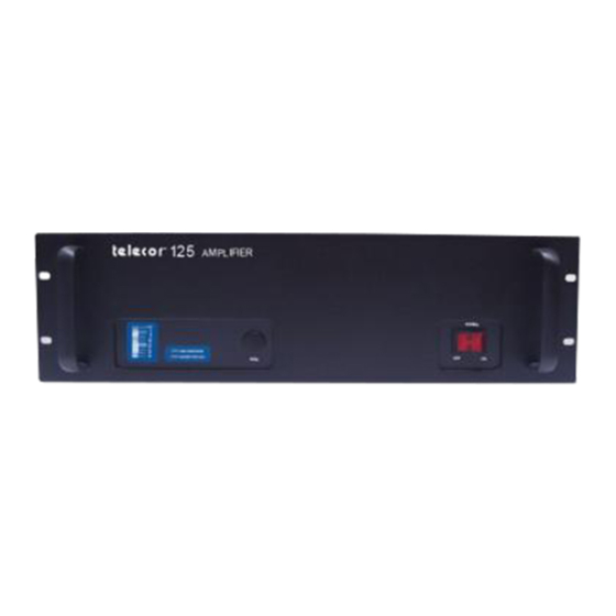
Page 2: Unit Description
Unit Description The various amplifier parts are: Figure 1: SI-125 Front View VU METER: The 30 dB digital VU meter shows 0 dB when the amplifier is operating at its rated output. Exceeding the rated output will cause the output to be clipped, which will be indicated by the illumination of the CLIP light. - Page 3 10 kΩ. The input signal level should be in either the 1 V or 100 mV range with the Input Level switch set to the appropriate position. The GND terminal is provided, if required, for grounding the cable shield. SI-125 Power Amplifier Manual...
-
Page 4: Installation
DO NOT ATTEMPT TO INSTALL EQUIPMENT THAT WAS RECEIVED DAMAGED. The amplifier mounts into a standard 19" Telecor equipment rack with 10-32 screws. The SI-125 requires 5 ¼" of vertical rack space. When mounting the amplifier into a rack with other equipment, be sure to allow for adequate ventilation. - Page 5 GAIN Control to 0, set the Input Level switch to 100 mV, and then increase the gain. Ensure that the amplifier is OFF before making, removing or handling any input or output connections. The output cover must be in place when the amplifier is operating. SI-125 Power Amplifier Manual...
-
Page 6: Operation
These switches do not adversely affect the operation of the amplifier. When measuring load impedance on a Telecor installation, disconnect the amplifier output from the line, connect the impedance meter across the line, make sure the system is in an ALL CALL mode, and then measure the line’s impedance and check for line ground faults. -
Page 7: Optional Modules
Note: These modules must be ordered at the same time as the SI-125 Amplifier as they cannot be installed in the field at a later time. These modules are installed on the rear of the amplifier by the Telecor factory and therefore cannot be ordered independently without an amplifier. -
Page 8: Specifications
5 ¼" H x 19” W x 12 ⅛" D (without amplifier handles) Finish Black Powder Coating PA-AM Power Amplifier Attenuator Module Optional Modules PA-MM Power Amplifier Monitor Module PA-PM Power Amplifier Paging Module Specifications are subject to change without notice. SI-125 Power Amplifier Manual... -
Page 9: Limited Warranty Policy
Telecor Inc. warrants all products bearing the Telecor name to be free from defects in material and workmanship under normal use and service for a period of one year from date of delivery. Telecor will repair or replace (at our option), free of charge, any unit that is found to be defective and returned to us under warranty.
Need help?
Do you have a question about the SI-125 and is the answer not in the manual?
Questions and answers