
Summary of Contents for MTS Systems MK292
- Page 1 T e m p o s o n i c s ® P o s i t i o n S e n s o r s MK292 Digital Output Module Users Manual 0797 550414 Revision B...
- Page 2 800-633-7609 Fax: 919-677-0200 S h i p p i n g A d d r e s s MTS SYSTEMS CORPORATION Sensors Division 3001 Sheldon Drive Cary, North Carolina 27513 O f f i c e H o u r s Mon.
-
Page 3: Table Of Contents
DETAILED PROGRAMMING PROCEDURE (RUN) Programming Mode (REC) Pulse Duration (SC) Scale Factor (RE) Resolution (MR) Measuring Range (ZERO) Null Adjust (ZERO) Offset (RUN) Operation Mode OPTIONAL ANALOG OUTPUT FOR THE MK292 Operation Mode 1 (Normal) Operation Mode 2 (Programmable Adjustment) -
Page 5: Introduction
DATA HOLD. An optional sub-board assembly provides an analog output for recording purpos- es (output range: 0 to 10 Vdc or 10 to 0 Vdc). The MK292 can be configured as either a rack-mountable card or module that can be installed in a standard 19 inch mounting rack. -
Page 6: System Configuration
1.19 in. 170 mm 30.2 mm MK 292 MK 292 Card 5.06 in. 128.4 mm Figure 1-2 MK292 Digital Output Module Dimensions 1.1 System Configuration 24 Vdc 5 Vdc Power Suppy Required for Required TTL Output Temposonics Sensor with Start/Stop or PWM Output... -
Page 7: Specifications
MK292 Module, Front Panel: 50.4 x 128.4 mm (1.98 x 5.06 in.) * When using the MK292 with a Temposonics LA or LP sensor, please contact Applications Engineering. Specifications are subject to change without notice. Consult MTS for verification of specifications critical to your application. -
Page 8: Temposonics Position Sensor Specifications
Outputs (absolute): Start/stop or PWM configured for external interrogation Mounting Distances: Sensor with RS422 output to MK292: 500 meters (1640 ft.) Sensor with PWM output to MK292: 152.4 meters (500 ft.) MK292 to PLC: 25 meters (82 ft.) Specifications are subject to change without notice. Consult MTS for verification of specifications critical to your application. -
Page 9: System Components
3. System Components 3.1 MK292-Compatible Temposonics Position Sensors To interface with the MK292, a start/stop or pulse-width modulated output (see figure 3.1) is required from the Temposonics position sensor. The MK292 will convert these signals into a parallel BCD, Gray Code, or binary output. -
Page 10: Connections
Wire Color Function Blue Gate (-) Green Gate (+) Yellow Interrogation (-) Orange Interrogation (+) Power, provided by MK292 (+15, ± 10%) Black Ground No Connection Drain Shield Drain Wire No Connection Figure 4-2a Figure 4-2b Integral Connector Hanging Connector... -
Page 11: Temposonics L Series Position Sensors With Start/Stop Output
Pink (+) Gate Yellow (+) Interrogation Green (-) Interrogation Red or Brown Power supplied by MK292 (+ 24 Vdc) White DC Ground No Connection Figure 4-3 RG Connector Table 4-C.2 Connections - Temposonics L Series Position Sensor with MS Connector... - Page 12 Connection Pin No. Wire Color Function White DC Ground No Connection Gray (-) Gate Pink (+) Gate Power supplied by MK292 (+ 24 Vdc) No Connection No Connection No Connection Yellow (+) Interrogation Green (-) Interrogation Figure 4-5 RB Connector (Mating Connector: P/N 400755-3) Table 4-C.4 Connections - Temposonics L Series Position Sensor with RO Integral Cable...
-
Page 13: System Connections
DC Common DC Common or Gray Code DC Common c1 or a1 24 V 24 V + 24V Input to MK292 c2 or a2 5-24V Input for TTL Output c3 or a3 EXAMPLE: Error For 5 - 24 V input... -
Page 14: Functional Inputs/Outputs
4.3 Functional Inputs/Outputs OUTPUTS: Voltage Level: TTL level to 24 Vdc Maximum Current Load: 20 mA (high level) INPUTS: Control Signal Level: ≥ applied Vin level Current Load per Input: < 1 mA 4.3.1 Error Output (Loss of Feedback) Pin: c5 Logic: HIGH: No Error;... -
Page 15: Data-Hold Input (Latch Inhibit)
4.3.3 Data-Hold Input (Latch Inhibit) Pin: c17 Logic: HIGH Data Hold is another means, besides Data Ready, to ensure that paral- lel data transfer does not occur during data update. When Data Hold (C17) is high, data does not update. 4.3.4 External Start Input (Features) Pin: c16 Logic: HIGH... -
Page 16: System Parameters
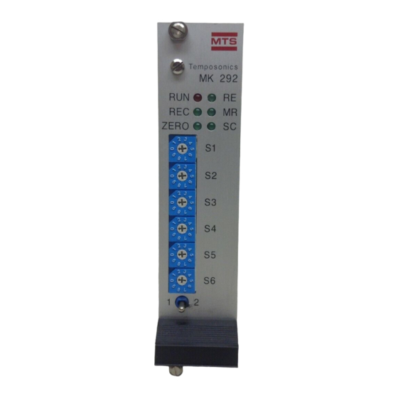
< < System parameters are set via the front panel of the MK292 using the programming and BCD switches. • Programming Switch This momentary toggle switch is located at the bottom of the front panel. It has two activation posi- tions: #1 and #2. - Page 17 BCD Switches Programming Switch Figure 5-2 Figure 5-3 Front Panel of MK292 Module BCD Switch • LEDs There are six LEDs, one red and five green, which give visual indication of the operating condition and programming mode of the MK292.
-
Page 18: Short Form Programming Procedure
Programming Mode has been exited and the Operation Mode is ready. Position #1 Normal Position #2 Position Figure 6-1 Programming Switch Positions For detailed instructions on programming the MK292 Digital Output Module, refer to Section 7 of this manual. -
Page 19: Detailed Programming Procedure
7. Detailed Programming Procedure 7.1 (RUN) Programming Mode / Red LED During initial start-up, the red 'RUN' LED will flash. This indicates that the MK292 is in the programming mode and input parameters are required for operation. If the 'RUN' LED is on, but not flashing, this means that parameters have already been set. - Page 20 Switch Setting: PWM Output (circulations) BCD Switch Circulations: 4 Circulations: 16 1) Hold the programming switch in Position #2 until the 'SC' LED is flashing (≈ 3 sec.) ADJUST The MK292 is now ready to accept the next parameter – Scale Factor (SC).
-
Page 21: Sc) Scale Factor
7.3 (SC) Scaling Factor / Green LED Each Temposonics position sensor has its own specific scale factor (gradient) which describes the velocity of the torsional strain pulse through the waveguide medium (refer to 'Principle of Operation'). The gradient is indicated on the sensor's label. Upon initial start-up or when replacing sensors, this value must be set to recalibrate system. -
Page 22: Re) Resolution
The MK292 is now ready to accept the next parameter – Resolution (RE). 7.4 (RE) Resolution / Green LED The resolution that can be achieved by the MK292 is dependent on the input from the Temposonics position sensor. The chart below indicates the range of resolutions depending on sensor type. -
Page 23: Mr) Measuring Range
Inches x 25.4 Circulation Count = N 1) Hold the programming switch in Position #2 until the 'ZERO' LED begins to flash (≈ 3 sec.) SETUP The MK292 is now ready to accept the next parameter -- Null Adjust (ZERO). -
Page 24: Zero) Null Adjust
7.6 (ZERO) Null Adjust / Green LED Null adjust allows you to set the mechanical ZERO position anywhere within the active measuring range of the position sensor. Move the sensor magnet to the desired ZERO position and proceed as follows: ZERO 1) Hold the programming switch in Position #2 until the 'ZERO' LED begins to flash (≈... - Page 25 Move the magnet to the desired mechanical start position and calibrate the offset as follows: OFFSET 1) Hold the programming switch in Position #2 until the 'ZERO' LED begins to flash (≈ 3 sec.) ADJUST The displacement output indicated position without the offset calculation 2) Enter the desired offset value using BCD switches S1-S6.
-
Page 26: Run) Operation Mode
1) Hold the programming switch in Position #1 until the 'RUN' LED begins to flash (≈ 3 sec.) SETUP The Programming Mode is exited and all parameter settings are stored in an EEPROM within the MK292 module. You are now in Operation Mode. -
Page 27: Optional Analog Output For The Mk292
8. Optional Analog Output for the MK292 (for Recording Purposes Only) NOTE: The analog output is available as an option and must be specified at the time of order. An additional analog sub-print is required. The analog output option functions in two operational modes: 1. -
Page 28: Operation Mode 2 (Programmable Adjustment)
If the magnet leaves the defined measuring range of the sensor, the system will indi- cate the following outputs: 1. If the magnet leaves the measuring range moving towards the end of the sensor rod, the output voltage will be NEGATIVE. 2. - Page 29 EXAMPLE, BCD Switch Settings SP1 = + 7.565 V SP2 = - 9.480 V S1 = 5 S1 = 0 S2 = 6 S2 = 8 S3 = 5 S3 = 4 S4 = 7 S4 = 9 S5 = 0 S5 = 0 S6 = 0 S6 = 9...
- Page 30 Fax: 919-677-0200 Phone: +49-23-5195870 Phone: +3-3239-3003 Fax: +49-23-5156491 Fax: +3-3262-7780 Temposonics is a registered trademark of MTS Systems Corporation. All Temposonics products are covered by US patent number 5,545,984. Other patents pending. 0797 550414 Revision B © 1997 MTS Systems Corporation...
Need help?
Do you have a question about the MK292 and is the answer not in the manual?
Questions and answers