Table of Contents
Advertisement
Operation, Installation and Service Manual
Original Documentation / Keep for Future Reference
Analogue Compass Repeaters
Types 5016-CA, 5016-CB, 5016-CC, 5016-CD
with RS-422 Serial Interface
056376/A; 05016-0128-02, 03 Feb 2015
Northrop Grumman Sperry Marine B.V. (Representative Office)
Woltmanstr. 19 • D-20097 • Hamburg, Germany
Tel.: +49-40-299 00-0 • Fax: +49-40-299 00-146 • E-mail: service.eu@sperry.ngc.com
Advertisement
Table of Contents

Summary of Contents for Sperry Marine 5016-CA
- Page 1 Analogue Compass Repeaters Types 5016-CA, 5016-CB, 5016-CC, 5016-CD with RS-422 Serial Interface 056376/A; 05016-0128-02, 03 Feb 2015 Northrop Grumman Sperry Marine B.V. (Representative Office) Woltmanstr. 19 • D-20097 • Hamburg, Germany Tel.: +49-40-299 00-0 • Fax: +49-40-299 00-146 • E-mail: service.eu@sperry.ngc.com...
- Page 2 © 2015 Northrop Grumman Sperry Marine B.V. This document and the information herein is the intellectual property of Northrop Grumman Sperry Marine B.V. [NGSM BV] and it’s associate companies and may not be copied, reproduced or translated without the express permission of NGSM BV.
-
Page 3: Table Of Contents
Analogue Compass Repeaters 056376/A Contents Safety Instructions Safety Notice Conventions ............... vii General Safety Information for the Operator ........viii General Safety Information for Service Personnel ........x Chapter 1: Introduction System Description................... 1-1 Intended Use ..................... 1-1 Not Intended Use ..................1-1 Design and Main Features................ - Page 4 Serial Dimming Command Evaluation ..........6-13 Chapter 7: Troubleshooting Basic Service Checks ................7-1 All repeater types 5016-CA, -CB, -CC, -CD ..........7-1 All repeaters, except bearing repeater, type 5016-CA ......7-2 Viewing Error Information in SUSI ............7-3 Analogue Repeater Error Page ..............7-3 Error IDs and Descriptions................
- Page 5 Analogue Compass Repeaters 056376/A Abbreviations Appendix Setup and Configuration Tables Drawings...
- Page 6 056376/A Analogue Compass Repeaters...
-
Page 7: Safety Instructions
Analogue Compass Repeaters 056376/A Safety Instructions Safety Notice Conventions The following safety notice conventions are followed throughout this manual: A Danger notice contains an operating or main- DANGER tenance procedure, practice, condition, state- ment, etc., which, if not strictly observed, will result in injury or death of personnel. -
Page 8: General Safety Information For The Operator
In case of minus temperatures always be extremely careful not to touch the metal housing of the bearing repeater to avoid freeze of hands and fingers. The capacitive keys of the bearing repeater 5016-CA are sensitive against Note surface water, e.g. remaining rain drops, which may result in random changing of the illumination brightness. - Page 9 056376/A CAUTION Risk of damage though solar radiation The bearing repeater 5016-CA is equipped with a cover plate for protec- tion against solar radiation. It is recommended to always protect the bearing repeater with the cover plate when not in use.
-
Page 10: General Safety Information For Service Personnel
CAUTION Risk of damage through unauthorized service The housing of the bearing repeater 5016-CA is designed for increased watertightness and shall therefore not be opened in the field. Opening the housing in the field will diminish the watertightness and may lead to condensation forming on the inside surfaces, especially the top glass, at a later point in time. - Page 11 Analogue Compass Repeaters 056376/A CAUTION Risk of parameter settings loss It cannot be guaranteed that the repeater’s configuration parameter set- tings are left intact during a firmware update. Before updating firmware, record all parameter settings to be able to re- enter them manually, if required.
- Page 12 056376/A Analogue Compass Repeaters...
-
Page 13: Chapter 1: Introduction
The prismatic azimuth device PV23 is a classified compass bearing device designed for usage together with the bearing repeater 5016-CA. Not Intended Use The analogue compass repeaters are not allowed to be used for the nav- igation of inland water vessels and river boats. -
Page 14: Design And Main Features
(secondary heading data), provided by a con- nected gyrocompass as active heading source (primary heading data), using a rotating compass card assembly. The repeaters are available in four type variants: • Bearing Repeater, Type 5016-CA • Steering Repeater, Type 5016-CB • Magnetic Heading Repeater, Type 5016-CC •... -
Page 15: Functional Description
Analogue Compass Repeaters 056376/A The magnetic heading repeater, type 5016-CC, is preconfigured to indi- cate magnetic compass heading only, regardless of which source is cur- rently active. The magnetic heading repeater is equipped with a removable cover, hid- ing the compass card when navigating the vessel under normal use, as the magnetic heading repeater is only classified for the indication of magnetic heading data in case of emergency when the gyrocompass(es) as primary heading source(s) are not available and the vessel is actually... -
Page 16: Compass Repeater Type Variants
1.4 Compass Repeater Type Variants Bearing Repeater The bearing repeater, type 5016-CA, is gimbal-mounted for usage in a bearing stand or in a repeater bracket attached to a bulwark. The bowl- shaped watertight housing with new glass front permits installation at exposed locations. -
Page 17: Bulkhead Repeater
Analogue Compass Repeaters 056376/A Bulkhead Repeater The bulkhead repeater, type 5016-CD, is equipped with the same com- pass card assembly as the steering repeater. It is suitable for mounting onto a bulkhead or other flat surface, vertically, horizontally or inclined. An optional mounting bracket is available to install the repeater at an inclined angle relative to the mounting surface. -
Page 18: Connection Box
Telescopic Alidade The telescopic alidade, stock no 60280, not classified as compass bear- ing device in combination with the bearing repeater, type 5016-CA, for classified vessels, may also become used with the bearing repeater for taking bearings on non classified ships only. -
Page 19: Technical Data
PC using a vendor-specific USB communications device class driver, directly accessible at the back side of types 5016-CB and - CC. For types 5016-CA and -CD the USB receptacle is accessible in- side the connection box housing. The analogue compass repeater is accessed via the “SUSI”... - Page 20 056376/A Analogue Compass Repeaters Bearing Repeater, Type 5016-CA Environmental Requirements protection grade IP 56 to DIN EN 60529 environmental conditions / EMC according to IEC 60945, equipment category “exposed to the weather” Magnetic Clearance to standard magnetic compass 0.80 m to steering magnetic compass 0.50 m...
- Page 21 Analogue Compass Repeaters 056376/A Steering Repeater, Type 5016-CB Environmental Requirements protection grade front side IP 56 to DIN EN 60529 back IP 23 to DIN EN 60529 environmental conditions / EMC according to IEC 60945, installed in console frame equipment category “protected from the weather”...
- Page 22 056376/A Analogue Compass Repeaters Magnetic Heading Repeater, Type 5016-CC Environmental Requirements protection grade front side IP 56 to DIN EN 60529 back IP 23 to DIN EN 60529 environmental conditions / EMC according to IEC 60945, installed in console frame equipment category “protected from the weather”...
- Page 23 Analogue Compass Repeaters 056376/A Bulkhead Repeater, Type 5016-CD Environmental Requirements protection grade IP 56 to DIN EN 60529 environmental conditions / EMC according to IEC 60945, equip- ment category “exposed to the weather” Magnetic Clearance to standard magnetic compass 0.70 m to steering magnetic compass 0.40 m reduced, to standard magnetic compass...
- Page 24 056376/A Analogue Compass Repeaters Bearing Stand, Type 4622 Dimensions and Weight diameter, top rim 444 mm height, type 4622-AC 1450 mm type 4622-AD 1300 mm weight 10 kg Bearing Repeater Bracket, Type 4890 Dimensions and Weight width 462 mm (including connection box fitted to right or left hand side) depth...
- Page 25 Analogue Compass Repeaters 056376/A Adjustable Bearing Repeater Bracket, Type 4905 Dimensions and Weight width 512 mm depth lowest position 560 mm highest position 308 mm height lowest position 231 mm highest position 481 mm weight 16.5 kg Bulkhead Repeater Bracket, Stock No. 26857 Dimensions and Weight width 241 mm...
- Page 26 056376/A Analogue Compass Repeaters Connection Box, Type 4894-AD Dimensions and Weight width 90 mm depth 60 mm height 164 mm weight 0.8 kg Azimuth Device PV23, Type 2535 Dimensions and Weight width 62 mm depth 230 mm height above re- 135 mm peater top glass weight...
-
Page 27: Declaration Of Conformity
D-20097 Hamburg, Germany as manufacturer hereby declares that the following specified equip- ment: “Analogue Compass Repeaters types 5016-CA, -CB, -CC, -CD” comply with the Marine Equipment Directive 96/98/EC, as amended. This equipment has been tested to verify compliance with the... - Page 28 056376/A Analogue Compass Repeaters 1-16 Declaration of Conformity...
-
Page 29: Chapter 2: Operation
Analogue Compass Repeaters 056376/A Chapter 2: Operation 2.1 Readout Elements, Indicators and Controls Figure 2-1: Readout elements, indi- cators and controls Lubber Line Indicates the “ahead” direction. Ship’s heading is read off the compass card(s) at the lubber line. 360° Card Indicates ship’s heading on a 360°... -
Page 30: Powering Up The Repeaters
The communication protocol and baudrate may be hard-set in the Note repeater configuration. This will disable auto-detection. Within a standard Sperry Marine NAVIGAT gyrocompass system, the analogue repeater will receive the heading source selection status from the compass system. If the NMEA 0183 protocol is used, the repeater evaluates the proprie- tary $PPLAN or $PPNSD sentences. -
Page 31: Reading Off Heading And Source Indication
Analogue Compass Repeaters 056376/A Only if no valid heading sentences are received at all, the repeater will raise an error. The error indicator will flash synchronously with one or all source indicators to indicate that no active heading data are currently received. -
Page 32: Adjusting The Illumination Brightness
056376/A Analogue Compass Repeaters 2.5 Adjusting the Illumination Brightness To adjust the backlight and keypad illumination brightness: Press DIM+ to increase the illumina- tion brightness. Press DIM- to reduce the illumination brightness. Reducing the illumination brightness also reduces the brightness of the Note source and error indicator LEDs. -
Page 33: Synchronizing The Compass Cards
2.8 Bearing Repeater Capacitive Keys Although the bearing repeater type 5016-CA is equipped with capacitive keys, in contrast to the push buttons of the compass repeaters types 5016-CB, -CC and -CD, there is no difference in functionality or handling neither with adjusting the illumination brightness, synchronizing the compass cards, nor with initiating the self test. -
Page 34: Taking Bearings With The Azimuth Device Pv 23
056376/A Analogue Compass Repeaters 2.9 Taking Bearings with the Azimuth Device PV 23 WARNING Risk of injury Permanent eye damage may result, when looking directly at the sun or at its reflection in the black azimuth mirror when using the azimuth device PV 23. - Page 35 Analogue Compass Repeaters 056376/A relative absolute bearing bearing 3. Read bearings: a) Read the object’s absolute bearing off the azimuth scale through the prism below the near sight. b) Read the object’s relative bearing off the verge ring scale at the index mark on the PV 23.
- Page 36 056376/A Analogue Compass Repeaters Taking Bearings with the Azimuth Device PV 23...
-
Page 37: Chapter 3: Error Indication
Cycle power. If the error persists, send the repeater back to Sperry Marine for exchange. heading timeout Check whether source provides valid heading data. In NAVIGAT compass systems, check that heading data originates from selected source according to $PPLAN/$PPNSD sentence. -
Page 38: Heading Timeout With Flashing Source Indicator
056376/A Analogue Compass Repeaters Heading Timeout with flashing Source Indicator In case of a heading timeout, one or all of the source indicators may flash in synchronously with the error indicator. This provides additional information regarding the cause of the timeout. •... -
Page 39: Chapter 4: Preventive Maintenance
Analogue Compass Repeaters 056376/A Chapter 4: Preventive Maintenance 4.1 Maintenance by Shipboard Personnel CAUTION Risk of damage through wrong cleaning agent The front plates of the compass repeaters are sensitive against aggres- sive cleaning agents as organic solvents or acetone. Do not clean the front plate with organic solvents, acetone or any other aggressive cleaning agent. -
Page 40: Maintenance Of Externally Installed Bearing Repeater
Maintenance of externally installed Bearing Repeater CAUTION Risk of damage though solar radiation The bearing repeater 5016-CA is equipped with a cover plate for protec- tion against solar radiation. It is recommended to always protect the bearing repeater with the cover plate when not in use. -
Page 41: Chapter 5: Installation
Analogue Compass Repeaters 056376/A Chapter 5: Installation 5.1 Bearing Repeater Installing Bearing Repeater with Bearing Stand CAUTION Risk of wrong installation Wrong positioning of the bearing stand will obstruct to take bearings. Always make sure that the bearing stand is so positioned that the ves- sel’s superstructure does not unduly obstruct the view of the horizon. - Page 42 056376/A Analogue Compass Repeaters 3. If the mounting surface is furnished with tapped holes, place the tubular spacers over the holes. If welded studs are provided, slide the spacers onto the studs. 4. Place the bearing stand on top of the spacers. The stand may be mounted in any of the four possible orientations.
- Page 43 Analogue Compass Repeaters 056376/A 17. Punch or cut a hole for the connection cables into the grommet, slide the grommet onto the cables and press it into the cable exit. 18. Remove the cover plate from the connection box. 19. Remove the cable jacket from the ends of the connection cables, draw back the cable screens and insert the cables into the connec- tion box through the cable glands.
-
Page 44: Installing Bearing Repeater With Bearing Bracket
056376/A Analogue Compass Repeaters Installing Bearing Repeater with Bearing Bracket CAUTION Risk of wrong installation Wrong positioning of the bearing stand will obstruct to take bearings. Always make sure that the bearing stand is so positioned that the ves- sel’s superstructure does not unduly obstruct the view of the horizon. In case one bearing stand does not allow to take bearings in a full circle of 360°, a second bearing stand must be installed for compensation. - Page 45 Analogue Compass Repeaters 056376/A 9. Locate the fixed trunnion in the bushing in the repeater. 10. Turn the loosened trunnion clockwise into the opposite bushing, so that the repeater is secured without play in the gimbal ring. Make sure that the repeater swings freely in the gimbal ring without jamming.
-
Page 46: Installing Bearing Repeater With Adjustable Bearing Bracket
056376/A Analogue Compass Repeaters Installing Bearing Repeater with Adjustable Bearing Bracket CAUTION Risk of wrong installation Wrong positioning of the bearing stand will obstruct to take bearings. Always make sure that the bearing stand is so positioned that the ves- sel’s superstructure does not unduly obstruct the view of the horizon. - Page 47 Analogue Compass Repeaters 056376/A 9. Turn the loosened trunnion clockwise into the opposite bushing, so that the repeater is secured without play in the gimbal ring. Make sure that the repeater swings freely in the gimbal ring without jamming. 10. Check that the repeater is centered in the gimbal ring. If necessary, adjust the trunnions to center the repeater.
-
Page 48: Steering Repeater / Magnetic Heading Repeater
The steering repeater, type 5016-CB, and the magnetic heading repeater, type 5016-CC; are supplied with four attachment columns and mounting clamps for installation in a standard Sperry Marine console frame or directly into a console cutout. In case of direct console mounting, the shipyard is to cut a square open- ing into the console as per dimension drawing 5016-0112-02. - Page 49 Analogue Compass Repeaters 056376/A To install the repeater directly in a console cutout: 1. Remove the four screws, clamps and washers from the attachment columns. This exposes four M 4 studs on the back of the repeater’s front plate. 2. Fit a clamp and washer onto each of the studs, rotate it inward and lightly fasten it with an attachment column.
-
Page 50: Bulkhead Repeater
056376/A Analogue Compass Repeaters 5.3 Bulkhead Repeater CAUTION Risk of damage The compass repeaters are heavy instruments. The compass repeater cables are not designed for holding the repeater just with the cable. Never hold or transport the repeater on the cable alone when installing or wearing a compass repeater. - Page 51 Analogue Compass Repeaters 056376/A 3. Install the connection box at an easily accessible location close to the repeater. 4. Remove the cover plate from the box. 5. Shorten the repeater and shipside connection cables as required. 6. Remove the cable jacket from the ends of the connection cables, draw back the cable screens and insert the cables into the connec- tion box through the cable glands.
- Page 52 056376/A Analogue Compass Repeaters 5-12 Bulkhead Repeater...
-
Page 53: Chapter 6: Configuration
If configuring a repeater using other settings than the factory defaults, note all settings in the analogue compass repeater setup table (see Appendix). Send a copy of the filled-out table to Sperry Marine for inclu- sion in the ship’s file. - Page 54 056376/A Analogue Compass Repeaters To configure the analogue repeater: 1. If the repeater is currently powered up, switch off the power first. 2. Gain access to the repeaters USB service port receptacle: – In case of a steering or magnetic heading repeater, remove the plastic plug from the back of the housing to access the receptacle on the repeater PCB.
- Page 55 Analogue Compass Repeaters 056376/A 8. Plug in the USB cable at the PC and at the repeater’s service port. The “Online” button should now become clickable (not greyed-out), indicating that SUSI has found a device to connect to: The LED icon next to the button will remain grey, as no connection has been made yet.
- Page 56 056376/A Analogue Compass Repeaters 10. If the service PC has not previously been used to service an ana- logue repeater, a warning message will pop up, indicating that the parameter list for the device is empty: Click to read the current configuration from the repeater and to set the Main page parameter controls accordingly, or click if you intend to set all parameters manually in SUSI...
- Page 57 Analogue Compass Repeaters 056376/A 15. To finish off the configuration, click in the SUSI applica- tion to read all configuration and calibration settings from the ana- logue repeater back into SUSI’s runtime memory. A dialogue box will pop up, asking whether these parameters should be saved as default settings for this device: 16.
-
Page 58: Configuration Parameters
056376/A Analogue Compass Repeaters 6.3 Configuration Parameters The analogue repeater application main page contains the settable con- trols to configure the repeater as required for the installation at hand. Figure 6-1: Controls on the repeater application main page Read-Only Controls: Repeater Serial No. -
Page 59: Rcs Type
Analogue Compass Repeaters 056376/A RCS Type Sets the repeater device type. Settings: automatic Recognize heading data from gyrocompasses, THDs and magnetic compasses. This is the factory default setting. If data is received in the NMEA 0183/IEC 6116 protocol, the repeater determines the active heading source according to the following scheme: Check the incoming data for $PPLAN or $PPNSD sentences according to the “Status Selection”... -
Page 60: Protocol Type
056376/A Analogue Compass Repeaters Protocol Type Selects the data protocol type. Settings: automatic Auto-detect the input protocol type, NMEA 0183/IEC 61162 or Plath binary. NMEA Recognize the NMEA 0183/IEC 61162 protocol only. Plath Recognize the Plath binary protocol only. Baudrate Selects the input baudrate (effective for the NMEA 0183/IEC 61162 proto- col only). -
Page 61: Gyro Selection
Analogue Compass Repeaters 056376/A Gyro Selection Selects the accepted NMEA 0183/IEC 61162 sentences for gyrocompass and THD headings. Settings: automatic No restriction. Accept, in the following order of priority: - $HETHS, - $--THS with any other talker ID (except HC), - $HEHDT, - $--HDT with any other talker ID (except HC). -
Page 62: Status Selection
056376/A Analogue Compass Repeaters Status Selection Selects the accepted NMEA 0183/IEC 61162 sentences for heading source selection. This setting is only effective in Sperry NAVIGAT gyrocompass systems, which generate the respective proprietary “nav. status” sentences. Settings: automatic No restriction. Accept, in the following order of priority: - $PPLAN - $PPNSD PPLAN... -
Page 63: Dimming Offset
Analogue Compass Repeaters 056376/A Dimming Offset Sets a local offset for the brightness level. Setting: -7 – +7 Select an offset as required to match the brightness of the repeater to that of other equipment controlled through the same dimming command device. Offsets below 0 decrease, offsets above 0 increase the repeater’s overall brightness by the corresponding number of brightness levels. -
Page 64: Dimming Values
056376/A Analogue Compass Repeaters 6.4 Dimming Values The illumination intensities at the repeater’s eight discrete brightness levels are factory preset to provide a useful range of levels under most lighting conditions, both at day and night. However, to permit an optimum adaptation of the repeater to local light- ing conditions, a configurable dimming value table is maintained in the on-board memory. -
Page 65: Serial Dimming Command Evaluation
Analogue Compass Repeaters 056376/A Serial Dimming Command Evaluation When serial dimming is used, the analogue repeater reads the com- manded brightness percentage from the $--DDC or $PPLAI sentence, respectively. At a dim offset of 0, the range of possible percentage val- ues, is mapped to the repeater’s eight brightness levels as follows: Table 6-1: commanded percentage... - Page 66 056376/A Analogue Compass Repeaters 6-14 Dimming Values...
-
Page 67: Chapter 7: Troubleshooting
Chapter 7: Troubleshooting CAUTION Risk of damage through unauthorized service The housing of the bearing repeater 5016-CA is designed for increased watertightness and shall therefore not be opened in the field. Opening the housing in the field will diminish the watertightness and may lead to condensation forming on the inside surfaces, especially the top glass, at a later point in time. -
Page 68: All Repeaters, Except Bearing Repeater, Type 5016-Ca
056376/A Analogue Compass Repeaters All repeaters, except bearing repeater, type 5016-CA • Visual inspection of mechanical components, the PCB and wiring. • Checks of the on-board supply voltages and I/O signals and data. The presence of voltages, signals and data is indicated by diagnostic LEDs on the PCB. -
Page 69: Viewing Error Information In Susi
Analogue Compass Repeaters 056376/A 7.2 Viewing Error Information in SUSI Analogue Repeater Error Page When connected to an analogue repeater, the Sperry Universal Service Instrument application (SUSI) provides an “Errors” page which displays the current activity and confirmation state of a number of possible error conditions and counts their occurrence since the last power-up: Figure 7-1: SUSI errors page... -
Page 70: Error Ids And Descriptions
056376/A Analogue Compass Repeaters Error IDs and Descriptions Table 7-1: description text cause corrective action Analogue repeater group 100: general errors error IDs "SPI/FRAM I/O Er- unable to read/ Cycle power. ror" write configuration Re-enter configura- settings tion parameters via SUSI. - Page 71 360° card to synchronize, re- "LB2 not found" unable to detect 10° turn repeater to card zero position Sperry Marine for exchange. "stepper power" stepper motor Check actual volt- phase supply volt- age from 24 VDC age too low supply.
-
Page 72: Location Of Parts On The Analogue Repeater Pcb
The analogue compass repeaters are complex electronic devices, which are not serviceable in the field down to the level of individual circuit com- ponents. Defective units must be sent back to Sperry Marine for repair. CAUTION Risk of damage of electrostatic-discharge-sensitive components The analogue compass repeaters contain electrostatic sensitive compo- nents. -
Page 73: Terminal Boards And Connectors
Analogue Compass Repeaters 056376/A Terminal Boards and Connectors Table 7-1: Function Terminal boards TB 1 stepper motor connection terminal block and connectors connector for repeater cable; connects to 24 VDC supply, Data input, ext. USB service interface Ethernet connector (for future use, currently not functional) USB service interface connector RS-232 service interface connector (for factory use only) connector for repeater cable shield... - Page 74 056376/A Analogue Compass Repeaters Location of Parts on the Analogue Repeater PCB...
-
Page 75: Chapter 8: Corrective Maintenance
The analogue compass repeaters are complex electronic devices, which are not serviceable in the field down to the level of individual circuit com- ponents. Defective units must be sent back to Sperry Marine for repair. The analogue compass repeaters are serviced and configured using the Note Sperry Universal Setup Instrument (SUSI). -
Page 76: Update Procedure
056376/A Analogue Compass Repeaters Update Procedure CAUTION Risk of parameter settings loss It cannot be guaranteed that the repeater’s configuration parameter set- tings are left intact during a firmware update. Before updating firmware, record all parameter settings to be able to re- enter them manually, if required. - Page 77 Analogue Compass Repeaters 056376/A 6. Plug in the USB cable at the PC and at the repeater’s service port. Power up the repeater. The “Online” button should now become clickable (not greyed-out), indicating that SUSI has found a device to connect to: The LED icon next to the button will remain grey, as no connection has been made yet.
- Page 78 056376/A Analogue Compass Repeaters The update tab provides file browsers to select firmware update files for the repeater’s system software (“MCU-Application”) and the bootloader (“MCU-Bootloader”). The option to update program code for an FPGA (“FPGA-Applica- tion“) is greyed out, as the repeater does not contain an FPGA. 9.
- Page 79 Analogue Compass Repeaters 056376/A 10. Click respectively to initiate the actual file upload. The bargraph at the bottom of the screen indicates the progress of the update: 11. When the update is complete, the message “Update OK” will be shown below the progress bar. Unplug the USB cable at the PC and at the repeater’s service port.
- Page 80 056376/A Analogue Compass Repeaters Updating the Repeater’s Firmware...
- Page 81 Analogue Compass Repeaters 056376/A Abbreviations Note The following list contains abbreviations and shortcuts used in this man- ual and in displayed text of CDU menus. 1x1 frame Standard frame 96x96 mm 6 step/° scale measure setting of servomotor A/DO-160 Section A, DO-160E, Environmental Conditions and Test Procedures for Airborne Equipment Acknowledge alarms Name of a Programming Language...
- Page 82 056376/A Analogue Compass Repeaters Control and Display Unit Course over ground COMP Compass Comp. Mon. Compass monitor CONST. Constant contd. Continued corr. Correction CORR. Correction cos. Cosine Carriage return D00 - D32 (D-Code, = Fault code) Digital analogue converter Direct Current D-Code Fault code (D00 - D32) DGPS...
- Page 83 Analogue Compass Repeaters 056376/A ECCN Export Control Classification Number ECDIS Electronic Chart Display and Information System e.g. exempli gratia (for example) Environmental conditions EM-Log Electromagnetic (speed) log European Norm ERR.STAT.BITS Validity check of fiber-optic sensor data status electrostatic discharge etc. et cetera (and so on) Ext Status In External status input port (TB 3.11)
- Page 84 056376/A Analogue Compass Repeaters Dual gyrocompass/Magnetic compass system Germanischer Lloyd Geographic position - latitude/longitude Gyro- /Magnetic compass system G/M headings Gyro /Magnetic compass headings GMDSS Global Maritime Distress and Safety System Ground GNSS Global Navigation Satellite System Global Positioning System GPS/AIS Global Positioning System / Automatic Identification System...
- Page 85 Analogue Compass Repeaters 056376/A Identifier i.e. id est (that is) International Electro Technical Commission International Hydrographic Office. International Maritime Organization Inertial Measurement Unit Integrated navigation system INT HDG ONLY Internal heading only INT/EXT HDG Internal or external heading International Protection Illustrated Parts Data Illustrated Parts List IPSU...
- Page 86 056376/A Analogue Compass Repeaters LEHMK Lehmkuhl (transmission standard company Lehm- kuhl) Line feed Litef Faser Kreisel (Litef fiber optic gyroscope) longitudinal ground speed lin. Linear lon. Longitude Lon. Longitude LORAN Long Range Navigation LORAN-C Long Range Navigation C Least significant Bit longitudinal water speed Meter Magnetic compass...
- Page 87 Analogue Compass Repeaters 056376/A Mod. Modul Mod. Modus Mod. 10/2 Gyrocompass container model 10/2 Mod. 10/3 Gyrocompass container model 10/3 Mod. 7/2 Gyrocompass container model 7/2 Most significant Bit Maritime Safety Committee MTBF Mean time between failure North NAUT-AW Class notation for enhanced nautical safety Naut-HSC Class notation for high speed craft Nav.
- Page 88 056376/A Analogue Compass Repeaters NMEA-HDM NMEA-HDM sentence NMEA-RMA NMEA-RMA sentence NMEA-RMC NMEA-RMC sentence n.o. Normally open Number None Volatile RAM Off Hdg Off heading alarm Offs. Offset Operational OUTP Output Pulse Phase P.Gnd Power ground Part number Pre-programmed IC Printed circuit board PLATH Binary protocol of company C.
- Page 89 Analogue Compass Repeaters 056376/A Rudder angle calibrator RADAR Radio Detection and Ranging Rudder angle indicator Random Access Memory (Analogue) Repeater Compass System Ref. Voltage Reference voltage Recommended minimum navigation information Recommended minimum navigation information NMEA sentence A RMA No. Return Material Authorization number Recommended minimum navigation information NMEA sentence B Recommended minimum navigation information...
- Page 90 056376/A Analogue Compass Repeaters Second SENS.D.M.OUTP. Output sentence format for magnetic compass head- ing at the sensor data output Sentence A self-contained line of data SFA unit Steering failure alarm unit S Gyro South gyro sin. Sine Steering mode switch Serial output data Speed over ground (actual measured speed of advance of a vessel over the surface of the earth)
- Page 91 Analogue Compass Repeaters 056376/A Temp. Temperature Transmitting magnet compass TMC function Transmitting magnet compass function TSS1 TSS1 protocol; Heading, pitch, roll, and heave mes- sage in the commonly used TSS1 message format Transistor-transistor-logic transversal water speed TxD NMEA FAST Fast serial data output UART Universal asynchronous receiver transmitter Universal digital repeater...
- Page 92 056376/A Analogue Compass Repeaters Watt West with with W/DO-160 Section W, DO-160E, Environmental Conditions and Test Procedures for Airborne Equipment without water speed, vector sum of lws and tws X rate Roll rate X/Y rates Roll and pitch rates Y rate Pitch rate Z/DO-160 Section Z, DO-160E, Environmental Conditions and...
- Page 93 Note After installation of the repeater, please return a filled-out copy of the Setup Table to Sperry Marine for inclusion in the ship’s file. When permanent changes are made to the system configuration, please return an updated copy of the Setup Table to Sperry Marine.
- Page 94 All appended documents and drawings are revision-controlled sepa- rately at Sperry Marine. In case of doubt, verify the current revision status of the drawings with Sperry Marine. This manual’s revision status does not change when the revision of an appended document or drawing changes.
- Page 95 Dimming Step 1 Dimming Step 2 Dimming Step 3 Dimming Step 4 Dimming Step 5 Dimming Step 6 Dimming Step 7 Dimming Step 8 Northrop Grumman Sperry Marine B.V. Woltmanstr. 19, 20097 Hamburg, Germany Tel.: +49-40-29900-0, Fax: +49-40-29900-146, E-mail: service.de@sperry.ngc.com...
- Page 97 Gewicht/Weight: 5,5 kg Schutzgrad/ Protection grade: IP56 NORTHROP GRUMMAN DATE NAME DIMENSION DRAWING SCALE Peiltochter 1:2,5 DRAWN 15.01.2015 Sperry Marine see ECO Typ 5016-CA HAMBURG GERMANY Bearing Repeater DRAWING No. SHEET Type 5016-CA 5016-0112-08 FIRST ANGLE DIMENSIONS IN SHEETS PROJECTION MILLIMETERS 984159 03.02.2015...
- Page 99 5016-0112-05 Square cut out for console mounting 181,5x181,5 NORTHROP GRUMMAN DATE NAME DIMENSION DRAWING SCALE Pulttochter 1:2,5 DRAWN 24.11.2009 Sperry Marine see ECO Steuertochter/ Magnettochter HAMBURG GERMANY Console Repeater DRAWING No. SHEET Steering/ Magnetic HDG repeater 984159 03.02.2015 5016-0112-02 983883 18.09.2013...
- Page 101 074883-0000-000 Schutzgrad/ Protection grade: IP56 5016-CD 074917-0000-000 NORTHROP GRUMMAN DATE NAME DIMENSION DRAWING SCALE Wandtochter 1:2,5 DRAWN 25.11.2009 Sperry Marine see ECO (RS 422) HAMBURG GERMANY Bulkhead Repeater DRAWING No. SHEET (RS 422) 984159 03.02.2015 5016-0112-03 982912 11.08.2010 FIRST ANGLE...
- Page 103 Gewicht/Weight: 3,5 kg NORTHROP GRUMMAN DATE NAME DIMENSION DRAWING SCALE Konsole 45°schwenkbar DRAWN 25.11.2009 Sperry Marine see ECO für Wandtochterkompass HAMBURG GERMANY Bracket 45° adjustable DRAWING No. SHEET for bulkhead repeater compass 5016-0112-04 FIRST ANGLE DIMENSIONS IN SHEETS PROJECTION MILLIMETERS 13.03.2010...
- Page 105 Rückseite/ Back: IP23 Square cut out for console mounting 181,5x181,5 NORTHROP GRUMMAN DATE NAME DIMENSION DRAWING SCALE Wasserdichter Einbau DRAWN 03.06.2010 Sperry Marine see ECO Pulttöchter Type 5016 HAMBURG GERMANY Watertight Installation DRAWING No. SHEET Console RepeatersType 5016 5016-0112-05 984159 03.02.2015...
- Page 107 / see also: 4881-0112-01 5016-0112-02 NORTHROP GRUMMAN DATE NAME DIMENSION DRAWING SCALE Adapterrahmen, kpl. DRAWN 05.09.2011 Sperry Marine für Retrofit von Typ 4881 see ECO HAMBURG GERMANY Adaptor Kit DRAWING No. SHEET for Retrofit of Type 4881 5016-0112-07 FIRST ANGLE...
- Page 109 SCREENED CABLE (CABLE Ø 8-10.5 mm). Gewicht/WEIGHT: 0,8 kg Schutzgrad/ Protection grade: IP65 NORTHROP GRUMMAN DATE NAME DIMENSION DRAWING SCALE Anschlusskasten DRAWN 29.05.2009 Sperry Marine see ECO für RCS 5016 HAMBURG GERMANY CONNECTION BOX DRAWING No. SHEET for RCS 5016 4894-0112-04 FIRST ANGLE DIMENSIONS IN...
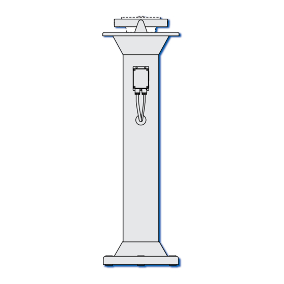
- Page 111 Rohr/Tube 200 MAX Gewicht/WEIGHT: 10 kg NORTHROP GRUMMAN DATE NAME DIMENSION DRAWING SCALE Peilsäule 1:10 DRAWN 23.10.2009 Sperry Marine see ECO mit Anschlusskasten HAMBURG GERMANY BEARING REPEATER STAND DRAWING No. SHEET with terminal box 4622-0112-03 FIRST ANGLE DIMENSIONS IN SHEETS...
- Page 113 5,2 kg Lagernr./Stock No. 74525 Weight without bearing repeater NORTHROP GRUMMAN DATE NAME DIMENSION DRAWING SCALE Peilkonsole DRAWN 14.10.2009 Sperry Marine see ECO mit Anschlusskasten HAMBURG GERMANY Bearing repeater bracket DRAWING No. SHEET with connection box 4890-0112-03 FIRST ANGLE DIMENSIONS IN...
- Page 115 Ohne Peiltochter Bearing Repeater not included Gewicht/WEIGHT: 16,5 kg NORTHROP GRUMMAN DATE NAME DIMENSION DRAWING SCALE Konsole höhenverst. DRAWN 26.10.2009 Sperry Marine see ECO mit Anschlusskasten HAMBURG GERMANY Bracket adjustable DRAWING No. SHEET with terminal box 4905-0112-03 FIRST ANGLE DIMENSIONS IN...
- Page 116 8x nut, cone washer, pan washer for correction of alignment error (±3°). NORTHROP GRUMMAN DATE NAME DIMENSION DRAWING SCALE Konsole höhenverst. DRAWN 26.10.2009 Sperry Marine see ECO mit Anschlusskasten HAMBURG GERMANY Bracket adjustable DRAWING No. SHEET with terminal box 4905-0112-03 FIRST ANGLE...
- Page 132 Sperry Marine Service: www.sperrymarine.com/offices Northrop Grumman Sperry Marine B.V. (Representative Office) Woltmanstr. 19 • D-20097 • Hamburg, Germany Tel.: +49-40-299 00-0 • Fax: +49-40-299 00-146 • E-mail: service.eu@sperry.ngc.com...
Need help?
Do you have a question about the 5016-CA and is the answer not in the manual?
Questions and answers