
Summary of Contents for Dahua Technology VTH2201DW
- Page 1 IP Audio Indoor Station Quick Start Guide V1.0.2 Please scan the QR code to view the user’s manual.
-
Page 2: Cybersecurity Recommendations
Cybersecurity Recommendations Mandatory actions to be taken towards cybersecurity 1. Change Passwords and Use Strong Passwords: The number one reason systems get “hacked” is due to having weak or default passwords. It is recommended to change default passwords immediately and choose a strong password whenever possible. - Page 3 site; just the NVR is needed. 7. Disable Auto-Login on SmartPSS: Those using SmartPSS to view their system and on a computer that is used by multiple people should disable auto-login. This adds a layer of security to prevent users without the appropriate credentials from accessing the system.
- Page 4 The network your NVR and IP camera resides on should not be the same network as your public computer network. This will prevent any visitors or unwanted guests from getting access to the same network the security system needs in order to function properly.
-
Page 5: Foreword
Foreword General This document mainly introduces installation and basic operation of IP audio indoor station. Safety Instructions The following categorized signal words with defined meaning might appear in the Manual. Signal Words Meaning Indicates a high potential hazard which, if not avoided, will result in death or serious injury. - Page 6 We are not liable for any loss caused by the operations that do not comply with the Manual. The Manual would be updated according to the latest laws and regulations of related regions. For detailed information, see the paper User's Manual, CD-ROM, QR code or our official website.
-
Page 7: Important Safeguards And Warnings
Important Safeguards and Warnings The following description is the correct application method of the device. Please read the document carefully before use, in order to prevent danger and property loss. Strictly conform to the document during application and keep it properly after reading. Power Requirement Please modify user’s default password timely after device deployment, in order to prevent ... -
Page 8: Table Of Contents
Table of Contents Cybersecurity Recommendations ........................II Foreword ................................V Important Safeguards and Warnings ......................VII 1 Product Overview .............................. 1 1.1 Front Panel ..............................1 1.2 Rear Panel Interface ..........................2 2 Device Installation ............................. 4 2.1 Before Installation ............................. 4 2.2 Installation .............................. -
Page 9: Product Overview
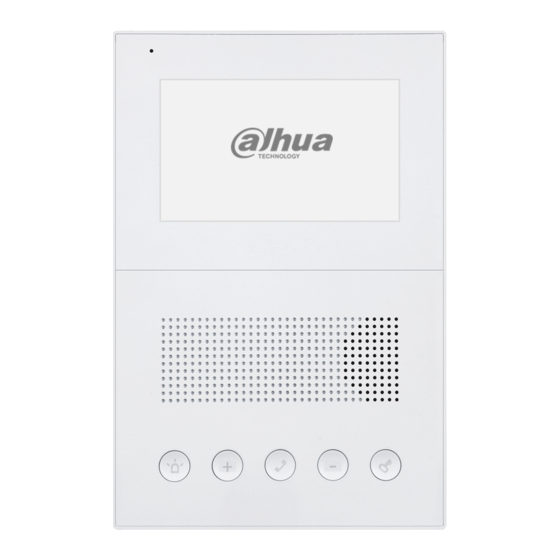
Product Overview Front Panel Figure 1-1 Name Description Microphone Audio input. Indicator light flashes: device deployment. Concealed indicator light Indicator light is normally on: the device is in DND status. Indicator light is off: the device is normal. Speaker Audio output. -
Page 10: Rear Panel Interface
Name Description the messages. In call status, press this key to reduce talk volume. Subtraction In standby status, press this key to reduce ring volume. Sign In standby status, press this key to reduce main VTH volume to 0, and the device enters DND status. - Page 11 Press this key shortly to carry out voice broadcast of present IP address. Press it for 5s, and the device restores factory defaults. Network Port Provide network communications and power supply function.
-
Page 12: Device Installation
Device Installation Before Installation Engineering installation and debugging shall be implemented by professional teams. In case of device faults, please don’t dismantle or repair by yourself; please contact our after-sales department. Try not to install VTH in poor environment, such as condensation, high-temperature, stained, dusty, chemically corrosive or direct sunlight environment. - Page 13 Figure 2-1...
-
Page 14: Device Debugging
Device Debugging Carry out debugging to ensure that the device can realize basic network access, call and monitoring functions after installation. Before debugging, please check whether the following work has been completed. Check whether there is short circuit or open circuit. Power on the device only after the ... - Page 15 Figure 3-1 Step 3 Enter “New Password” and “Confirm”, and click “Next”. The system displays “Protect” interface, as shown in Figure 3-2. This password is used to login WEB interface. It shall be at least 8 characters, and shall include at least two types of number, letter and symbol. Figure 3-2 Step 4 Select “Email”...
- Page 16 initialization succeeded!” Figure 3-3 Step 6 Click “OK”. The system displays WEB login interface, as shown in Figure 3-4. Figure 3-4 Step 7 Enter user name and password, and click “Login”. Log in the WEB interface of the device. Default user name is admin. ...
- Page 17 Figure 3-5 Step 2 Enter the planned “IP Address”, “Subnet Mask” and “Default Gateway”, and click “OK”. After modification is completed, VTO reboots automatically, while the following two cases occur at WEB interface. If PC is in the planned network segment, WEB interface jumps to new IP login ...
- Page 18 To support group call, tick “Enable”. After enabling group call, the device will reboot and put it into effect. Platform (VTSS5000) works as SIP server Select “Server Type” to be “VTSS5000”, and click “OK” to save configurations. To set “Building No.” and “Building Unit No.”, please turn on “Support ...
- Page 19 Parameter Description When VTO works as SIP server, SIP realm shall be VDP. SIP Realm When the platform works as SIP server, SIP realm can be null, or remain default value. Username of Sip Server Username and password to log in SIP server. Password Sip Server Table 3-1...
- Page 20 Figure 3-9 Step 4 Configure VTO parameters. Please refer to Table 3-2. Parameter Description VTO number. It is used during signaling interaction of SIP system. Use the Register Password default value. IP Address IP address of VTO. Username Username and password to login WEB interface of this VTO. Password Table 3-2 Step 5 Click “OK”...
- Page 21 Figure 3-10 Step 2 Click “Add”. The system displays “Add” interface, as shown in Figure 3-11. Figure 3-11 Step 3 Configure VTH parameters. Please refer to Table 3-3. Parameter Description Family Name Configure VTH username and nick name, just to distinguish First Name them.
-
Page 22: Vth Debugging
3.1.2 VTH Debugging VTH shall be debugged with VDPconfig tool. Please ensure that default IP addresses of PC and VTH are in the same network segment. Default IP address of VTO is 192.168.1.110. Step 1 Search the device. In VDPConfig tool, click “ ”. - Page 23 Figure 3-13 Step 2 Device initialization. 1. Select devices that have not been initialized. 2. Click The system displays “Device Initialization” interface, as shown in Figure 3-14. Figure 3-14 Select the device that shall be initialized, and click “Initialize”. The system displays “Device Initialization” interface, as shown in Figure 3-15.
- Page 24 Figure 3-15 Configure device initialization parameters. Please refer to Table 3-4 for details. Parameter Description Username Default username is admin. New Password Enter new password of the device, which consists of 6 numbers. Confirm Password Confirm the new password. It is ticked by default. This Email address will be used to reset the Email Address password.
- Page 25 Figure 3-16 Use the default settings; click “OK” to start initialization. On completion, the system displays Figure 3-17. will be displayed if initialization succeeded and will be displayed if initialization failed. Click the icon to view details. Figure 3-17 Click “Complete” to complete device initialization. On completion, device status on the main interface has turned into “Initialized”.
- Page 26 Step 3 Configure SIP server. 1. Click “ > Config”. The system displays “Config” interface, as shown in Figure 3-18. Figure 3-18 In the organization tree in the left, select IP of the device to be configured. Configure SIP server parameters in the right VTH. Please refer to Table 3-5 for details.
- Page 27 Figure 3-19 Click “Import” to select files. File template in the installation directory is named Project1. Please obtain it in advance, add VTO and VTH info according to template format requirements. IP address, gateway and subnet mask in the template shall be filled according to network planning.
-
Page 28: Debugging Verification
Figure 3-20 Debugging Verification Please refer to “4.1 Function of Talk with Management Center”, “4.2 Function of Talk with VTO” and “4.3 Unlock Function”; verify whether VTH debugging has succeeded. -
Page 29: Functional Operation
Functional Operation Function of Talk with Management Center 4.1.1 Call Management Center Press SOS key on the front panel in any status, and the VTH switches to call Management Center at once. If calls get through, VTH sends out beep sound, which is ringback tone. In case of failure, press SOS key on the front panel to finish calling. -
Page 30: Disenable Dnd
4.4.2 Disenable DND In standby status, press plus sign to increase volume and remove DND manually. In standby status, if main VTH volume is not 0, the device exits DND status, and the indicator light turns off. Arm and Disarm 4.5.1 Arm In disarm status, press “Plus Sign+ Call Key”... -
Page 31: Faq
Q: Fail to call VTH. How to deal with it? A: Please check whether network cable is inserted well; confirm whether corresponding unit VTO works normally. Q: VTH doesn’t ring when VTO calls. How to deal with it? A: Please check whether DND function has been enabled. Q: How to deal with problems that are not confirmed or cannot solved? A: Please consult professional technical support. -
Page 32: Appendix 1 Technical Parameter
Appendix 1 Technical Parameter Parameter Description Input 1 microphone input. Audio Output 1 speaker output. 5 mechanical keys: SOS, plus sign, call, subtraction Mechanical Key sign and unlock. Alarm Input 4 channels. Alarm Alarm Output 1 channel. Installation Installation with bracket. Power Supply DC 12V. -
Page 33: Appendix 2 Packing List
Appendix 2 Packing List Packing List The following devices and documents are included in the packaging box. Please check earnestly when opening the box and keep them properly. Name Quantity Note □ Main Device 1 unit □ 1 guide Quick Start Guide □...
Need help?
Do you have a question about the VTH2201DW and is the answer not in the manual?
Questions and answers