Table of Contents
Advertisement
Advertisement
Table of Contents

Summary of Contents for Cool Machines 1500 Series
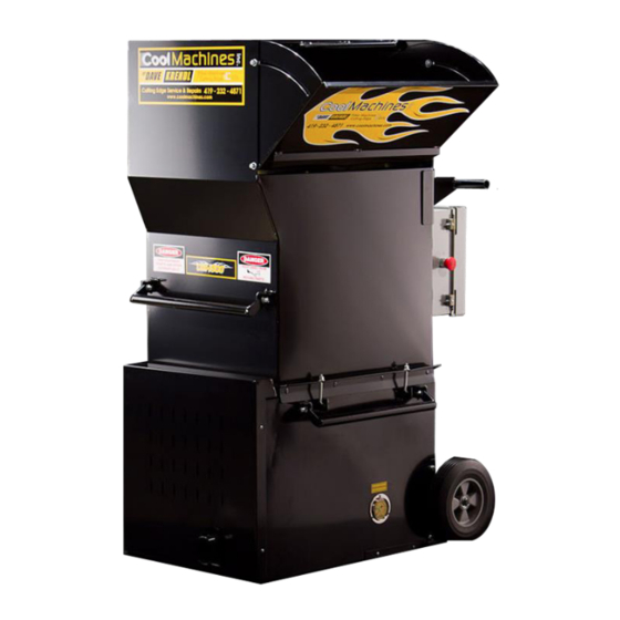
- Page 1 740 Fox Rd., Van Wert, OH 45891 419-232-4871 CM-1500S Owner’s Manual...
-
Page 2: Table Of Contents
CM-1500S Owner’s Manual Index: Index……………………………..……………….………..2 Safety / Caution…….……………………………………….3 Warranty…………….……………………………….……..4 Philosophy & Theory of Operation…………….….…..…...5 Unpacking and Machine Set-up……………………..……6 Operation and Controls……………………………..….….7 Pressure Gauge: How to Use it……………………...……11 Airlock and Seal Replacement………………………...….12 Maintenance……………………………………………..….13 ... -
Page 3: Safety / Caution
Safety/Caution Be Safe- Keep away from moving parts. Be Safe- Make sure all guards, and hopper extensions are in proper location before operating machine. Hands should never pass below top of main hopper. Be Safe- Do not move machine, remove motors, or other electrical components when unit is connected to power supply. -
Page 4: Warranty
This limited warranty does not cover replacement of components or parts manufactured by others than Cool Machines and become inoperative due to wear & usage and needs to be replaced on a regular basis. Including but not limited to: airlock seals, belts, chains, auger wipers, switches, fuses, fan blades, clutches, hoses, and filters. - Page 5 (Any duplication or use of this technology may be in violation of Cool Machines Inc. rights.) Cool Machines Inc. provides a solution offering the highest production and lowest power requirements. We provide compact designs with the highest quality materials; offering the highest durability, highest corrosion resistance, easiest maintenance, and simplest troubleshooting of any machine in its class.
- Page 6 Un-Packing and set-up of machine: Machine Specifications: Weight: Airlock: Blower/ Sizes: CM-1500 (single blower) 310lbs. 10” x 10” diameter (Before S#:CM-0723 ) one or two large blowers CM-1500 (double blower) 330lbs. 10” x 14” diameter (S#:CM-0723 -Present) one big & one small 3”...
-
Page 7: Operation And Controls
Operation and Controls: Control panel: Control panel enclosure contains the electrical components to select (on/off) operation of motors, control speed variations of blower(s), and protect the circuitry of main drive motor, blowers and auxiliary devices. (If machine does not function properly, disconnect power and check manual thermal overload breakers on front of the main panel box.) To start machine, make sure power supply (grid/shore power or generator) is appropriate (120 or 230/240 volts overseas), and power is turned ‘on’. - Page 8 Domestic Control Panel Blower Control Voltmeter Kill Switch (On Side) IWS Outlet Auxiliary Outlet Main Input Power ‘3’- Position Selector Switch Remote Outlet Functions of the various switches and outlets are indicated below. Blower Control: Increase or decrease air supply to the blowing hose. ...
- Page 9 ‘CE’ Overseas Control Panel: ‘4-Position’ Selector Switch Control panels for ‘CE’ specifications will have additional control features designed to conform to European standards. These additional features include: Main panel disconnect, finger safe connections and terminals inside panel box, 24 volt transformer power light, power drop-out button and manual re-start relay function, 4-position selector switch, and a pre-alarm warning beeper Signal.
- Page 10 Feed Gate control: The control of fiber feed rate is adjusted with the slide gate located (under main control panel), below the hopper area. The slide gate controls the opening to the airlock and can be adjusted with reference to the ‘pin’ and ‘hole’ locations on the slide plate. See illustration below: Feed gate Adjustment Pin Feed Gate Control Feed Gate Settings (Approx.)
-
Page 11: Pressure Gauge: How To Use It
Pressure Gauge: How to Use it This machine includes a recessed pressure gauge located in the lower base unit directly below the fold-out loading door. The pressure gauge has two functions: 1. Calibrate air pressure for effective dense packing (cellulose) and reducing the chance of pushing drywall from the studs. - Page 12 Airlock Seal Replacement Auger Removal Instructions (For CM-700 and CM-1500 models) IMPORTANT: Disconnect power and follow proper lock out/tag out procedures before proceeding. 1. Remove front chain guard access panel. 2. Removed hopper from base unit. 3. Loosen chain idler sprocket located on airlock end- plate, and remove chain.
-
Page 13: Maintenance
Maintenance: Daily: Empty fiber from machine daily. Clean blower filter(s). Brush off exterior when not running. (NOTE: Blower filter covers w/3” output tubes are available from factory) Feed Gate Adjustment Blower Filters / Keep Clean Weekly: Clean blower filter (remove and blow out with compressed air) and vacuum fiber and debris from under machine area. -
Page 14: Mechanical Troubleshooting
Mechanical Troubleshooting Problem Corrective Action Loud knocking sound A. Check scalping augers or airlock for objects and remove. B. Check chains for proper alignment and tension. C. Check for bent or misaligned auger/shredder fingers. 2) Poor output or uneven flow A. - Page 15 4) Blower motor running hot. A. Clean or replace filter(s) located on lower base unit, below slide gate. Check intake of blowers for debris/ insulation. Blow out blower motor and surrounding area with compressed air. B. Check blowing hose for blockage. A restriction in the output hose will cause the blowers to run hotter than normal.
- Page 16 Rev. 12/8/2017 Page 16...
- Page 17 Rev. 12/8/2017 Page 17...
- Page 18 Rev. 12/8/2017 Page 18...
- Page 19 Rev. 12/8/2017 Page 19...
- Page 20 Rev. 12/8/2017 Page 20...
- Page 21 Rev. 12/8/2017 Page 21...
- Page 22 Rev. 12/8/2017 Page 22...
- Page 23 Rev. 12/8/2017 Page 23...
- Page 24 Rev. 12/8/2017 Page 24...
- Page 25 Rev. 12/8/2017 Page 25...
- Page 26 Rev. 12/8/2017 Page 26...
- Page 27 Rev. 12/8/2017 Page 27...
- Page 28 Rev. 12/8/2017 Page 28...
- Page 29 Rev. 12/8/2017 Page 29...
- Page 30 Rev. 12/8/2017 Page 30...
- Page 31 Rev. 12/8/2017 Page 31...
- Page 32 Rev. 12/8/2017 Page 32...
- Page 33 Rev. 12/8/2017 Page 33...
- Page 34 Rev. 12/8/2017 Page 34...
- Page 35 Rev. 12/8/2017 Page 35...
- Page 36 Rev. 12/8/2017 Page 36...
- Page 37 Rev. 12/8/2017 Page 37...
- Page 38 Rev. 12/8/2017 Page 38...
- Page 39 Rev. 12/8/2017 Page 39...
- Page 40 Rev. 12/8/2017 Page 40...
- Page 41 Rev. 12/8/2017 Page 41...
- Page 42 Rev. 12/8/2017 Page 42...
- Page 43 Rev. 12/8/2017 Page 43...
- Page 44 Rev. 12/8/2017 Page 44...
- Page 45 Rev. 12/8/2017 Page 45...
- Page 46 Rev. 12/8/2017 Page 46...
- Page 47 Rev. 12/8/2017 Page 47...
- Page 48 Rev. 12/8/2017 Page 48...
- Page 49 Rev. 12/8/2017 Page 49...
Need help?
Do you have a question about the 1500 Series and is the answer not in the manual?
Questions and answers