Table of Contents
Advertisement
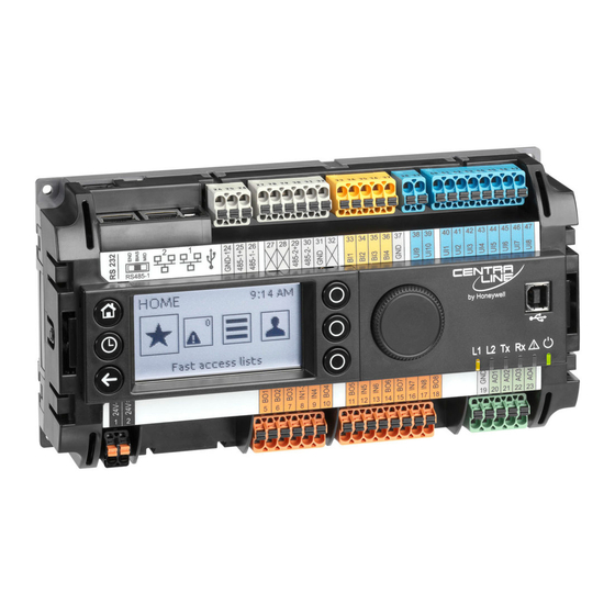
EAGLE Controller
Safety Information ................................................................ 2
General Safety Information ............................................... 2
Information as per EN 60730 ............................................ 2
WEEE Directive ................................................................ 2
Standards, Approvals, etc. ................................................ 2
3rd-Party Software Licenses ............................................... 2
Specifications of Controller ................................................. 3
System Overview .................................................................. 4
Overview of Models .......................................................... 4
System Architecture .......................................................... 5
Bus and Port Connections ................................................ 6
Mounting/Dismounting ...................................................... 12
Before Installation ........................................................... 12
Dimensions ..................................................................... 12
Wiring and Set-Up .............................................................. 14
General Safety Considerations ....................................... 14
Wiring Terminals ............................................................. 14
Power Supply .................................................................. 14
Terminal Assignment ...................................................... 15
RIN-APU24 ..................................................................... 16
Lightning Protection ........................................................ 16
CLEA2026Bxx Connection Examples ............................. 17
Internal I/Os of the EAGLE ............................................. 19
Engineering, Commissioning ............................................ 21
Required Preparations .................................................... 21
Behavior of Outputs during Download ............................ 21
Extra Parts .......................................................................... 22
Panel Bus Connection ....................................................... 23
Overview of Panel Bus I/O Modules ............................... 23
Panel Bus Considerations ............................................... 23
Connecting RS485-1 to Panel Buses .............................. 24
Connecting RS485-2 to Panel Buses .............................. 25
Addressing Panel Bus I/O Modules ................................ 26
Cable Specifications ....................................................... 26
® U.S. Registered Trademark
Copyright © 2018 Honeywell Inc. • All Rights Reserved
Installation &
Commissioning
Instructions
TABLE OF CONTENTS
LonWorks Communications ............................................. 27
General Information ....................................................... 27
BACnet MS/TP Bus Connection ....................................... 28
BACnet MS/TP Bus Considerations ............................... 28
Connecting RS485-1 to BACnet MS/TP Buses .............. 28
Connecting RS485-2 to BACnet MS/TP Buses .............. 30
Modbus Connection .......................................................... 31
Modbus Considerations .................................................. 31
Connecting RS485-1 to the Modbus .............................. 31
Connecting RS485-2 to the Modbus .............................. 32
M-Bus Connection ............................................................. 33
M-Bus Considerations .................................................... 33
M-Bus Connection Procedure ........................................ 34
Troubleshooting ................................................................ 35
EAGLE Controller Troubleshooting ................................ 35
Panel Bus I/O Module Troubleshooting .......................... 35
Appendix 1: Earth Grounding ........................................... 36
EAGLE Systems and SELV ........................................... 36
EAGLE Systems and Standard EN60204-1 ................... 36
Appendix 2 ......................................................................... 39
Sensor Input Accuracy ................................................... 39
Recognition of Sensor Failure of Sensor Inputs ............. 39
Sensor Characteristics ................................................... 39
Index ................................................................................... 42
Trademark Information
LON, L
W
ON
ORKS
Corporation registered in the United States and other
countries.
Network ........................... 27
, and Neuron are trademarks of Echelon
EN1Z-0970GE51 R0918
Advertisement
Table of Contents

Related Manuals for CentraLine EAGLE


Summary of Contents for CentraLine EAGLE
-
Page 1: Table Of Contents
Terminal Assignment ............15 EAGLE Systems and SELV ........... 36 RIN-APU24 ..............16 EAGLE Systems and Standard EN60204-1 ....36 Lightning Protection ............16 Earth Grounding of EN60204-1 Applicable Systems ..37 CLEA2026Bxx Connection Examples ......17 ... -
Page 2: Safety Information
IP30 (mounted in cabinet doors, with accessory MVC-80-AC2) If the EAGLE System is modified in any way, except by the ► manufacturer, all warranties concerning operation and Device meets BTL, AMEV AS-A, EN 60730-1, EN 60730-2- safety are invalidated. -
Page 3: Specifications Of Controller
EAGLE CONTROLLER – INSTALLATION & COMMISSIONING INSTRUCTIONS SPECIFICATIONS OF CONTROLLER Table 2. EAGLE specifications 19 … 29 VAC, 50/60 Hz or Power supply 20 … 30 VDC typically dc: 5 W; max. 6 W Power consumption typically ac: 9 VA; max. 11 VA typically dc: 210 mA;... -
Page 4: System Overview
EAGLE CONTROLLER – INSTALLATION & COMMISSIONING INSTRUCTIONS SYSTEM OVERVIEW Overview of Models Table 3. Overview of models order no. max. cable feature description length NTC10kΩ / NTC20kΩ / 0…10V / slow BI, 0.4 Hz 400 m NTC10kΩ / NTC20kΩ / 0…10V fix pull-up / slow BI, 0.4 Hz 400 m open = 24 V / closed 2.0 mA / totalizer 15 Hz... -
Page 5: System Architecture
EAGLE CONTROLLER – INSTALLATION & COMMISSIONING INSTRUCTIONS System Architecture An EAGLE System consists of the EAGLE Controller and various Panel Bus I/O modules. The EAGLE Controller provides interface connections, which allow connection to external systems (e.g., BACnet controllers). Via the IF-LON External Interface,... -
Page 6: Bus And Port Connections
– all models except CLEA2014B21 and CLEA2014B31 supplied with power from a dedicated transformer. However, if the EAGLE controller is to be supplied by the 4 RS485-1* (isolated; for BACnet MS/TP, Panel Bus, or same transformer powering other controllers or devices Modbus RTU Master communication) (e.g., the PW M-Bus Adapter), care must be taken to... - Page 7 EAGLE CONTROLLER – INSTALLATION & COMMISSIONING INSTRUCTIONS RS232 / RJ45 Socket Via its RS232 / RJ45 socket, the EAGLE Controller can be connected (using an XW586 cable) to a PW M-Bus Adapter and thus to M-Bus networks. See also section "M-Bus...
- Page 8 The recommended slide switch setting depends upon the RS485-1 status LED indicating reception location and usage of the given EAGLE – see Fig. 12 and yellow of communication signals. Table 5; it also depends upon the selected communication...
- Page 9 Further, according to U.L. requirements, each RS485 interface may be loaded with a max. of 32 unit loads. E.g., 550 OHM CentraLine devices have as little as ¼ unit load each, so that up to 128 devices can be connected. GND-1 BACnet MS/TP connections to the RS485 interfaces must comply with the aforementioned RS485 standard.
- Page 10 Each Modbus segment will require its own line polarization and line termination. Wiring Topology Only daisy-chain wiring topology is allowed. Modbus Master Specifications Modbus Compliance As per the Modbus standard, the EAGLE controller is a con- MODBUS MODBUS MODBUS ditionally compliant "regular" Modbus device. MASTER...
- Page 11 This cycle will be repeated endlessly. Lower Significant Word first If the EAGLE does not receive any response for a duration of six (6) seconds, the System Alarm "MODB COMM ERROR" will be issued. EN1Z-0970GE51 R0918...
-
Page 12: Mounting/Dismounting
US requirement, only: This device must be installed in a UL-listed enclosure offering adequate space to maintain the segregation of line voltage field wiring and Class 2 field wiring. In the case of vertical mounting on DIN rails, the EAGLE controller should be secured in place using a commercially-available stopper. - Page 13 Fig. 20. EAGLE Controller with built-in HMI (with MVC-80-AC1), dimensions (in mm) 57.5 215.5 Fig. 21. EAGLE Controller with RJ45 socket for CLEAHMI21 External HMI (with MVC-80-AC1), dimensions (in mm) NOTE: Use of the covers (MVC-80-AC1) obstructs access to the Ethernet and USB 2.0 Host Interfaces and RS232 socket.
-
Page 14: Wiring And Set-Up
1 and 2). See also Fig. 25. Do not touch any live parts in the cabinet. ► The power supply of the EAGLE Controller must conform to Do not open the controller housing. ► Safety Class II. To reduce overall current consumption, the Disconnect the power supply before making connections to ►... -
Page 15: Terminal Assignment
EAGLE CONTROLLER – INSTALLATION & COMMISSIONING INSTRUCTIONS Terminal Assignment Table 10. Terminal assignment signal Description 24V-0 supply voltage (GND), internally connected with term. 31 and system GND (term. 19+37) 24V~ supply voltage (24V) not used Binary output 1. N.O. relay contact switching input power connected to terminal 8 Binary output 2. -
Page 16: Rin-Apu24
See also section "Addressing Panel conforming to IEC61558-2-6. Bus I/O Modules" on page 26. In the U.S. and Canada, if the EAGLE is powered by trans- formers, then such transformers must be NEC Class-2 Powering Field Devices and EAGLE via Separate Transformers transformers. -
Page 17: Clea2026Bxx Connection Examples
EAGLE CONTROLLER – INSTALLATION & COMMISSIONING INSTRUCTIONS CLEA2026Bxx Connection Examples NTC20kOHM NTC20kOHM ACTIVE SENSOR TOTALIZER CONTACT SENSOR SENSOR 1: GND (24V 0) 1: GND 1: GND 1: GND 1: GND 2: 24V POWER 2: SIGNAL 2: SIGNAL 2: SIGNAL 2: SIGNAL 3: 0...10 VDC... - Page 18 The XS830 and XS831 Auxiliary Terminal Packages are optional accessories which can be mounted onto the top and/or bottom of the EAGLE Controller in order to equip them with additional terminals for the connection of, e.g., shields, sensors, GND, N, 230 V, or 24 V (but not earth!).
-
Page 19: Internal I/Os Of The Eagle
→ state=1 0.4 Hz 12-bit resolution resolution Pulse Counter Specifications Using CARE, the universal inputs of the EAGLE can be con- ±75 mV (0 ... 10 V) accuracy figured as pulse counters (totalizers). against short-circuiting, 24 VAC protection If the duty cycle is 50% / 50%, the pulse counter supports up to 0.4 Hz. - Page 20 → relay contact is opened Pulse Counter Specifications Using CARE, the binary inputs of the EAGLE can be con- figured as pulse counters (fast totalizers) for operation in conjunction with devices equipped with an open collector output.
-
Page 21: Engineering, Commissioning
CARE) position / state. (CLIOL82x) expires, outputs go to In order to access (with a laptop or PC) the EAGLE Controller safety position. via Ethernet/IP for the first time, you may employ any one of the following two options:... -
Page 22: Extra Parts
Set of ten terminals. Each Auxiliary Terminal Package consists of two groups of nine internally connected push-in terminals, for distributing signals / power. For the Mixed Panel Bus I/O Module and the EAGLE XS830 A1 A2 A3 A4 A5 A6 A7 A8 A9 B1 B2 B3 B4 B5 B6 B7 B8 B9 Controller, only. -
Page 23: Panel Bus Connection
EAGLE CONTROLLER – INSTALLATION & COMMISSIONING INSTRUCTIONS PANEL BUS CONNECTION The EAGLE Controller features two RS485 interfaces to which Panel Bus modules can be connected: RS485-1 (consisting of push-in terminals 24 [GND-1], 25, and 26) and/or RS485-2 (consisting of push-in terminals 29, 30, and 31 [GND-2]). -
Page 24: Connecting Rs485-1 To Panel Buses
Panel Bus I/O modules and field devices connected to them. Connecting RS485-1 to Panel Buses NOTE: When connecting RS485-1 of the EAGLE with Panel Bus I/O modules, it is recommended that the slide switch be set to "END." CentraLine I/O Module... -
Page 25: Connecting Rs485-2 To Panel Buses
120 Ohm 24V~ 24V~ 24~0 24~0 24 V 230 V Fig. 37. Connecting RS485-2 of the EAGLE with Panel Bus I/O Modules (single transformer) CentraLine I/O Module CentraLine I/O Module CentraLine I/O Module Com a Com a Com a RS485-2... -
Page 26: Addressing Panel Bus I/O Modules
– Shielding of cables leading to field devices must be twisted pair, shielded (foil or grounded only at one end. cable type braided shields are acceptable) – Do not connect the shield to the EAGLE Controller. charac. impedance 100…130 Ω distributed capa- Less than 100 pF per meter (30... -
Page 27: Lonworks Communications
This ORKS requires the use of an IF-LON2 (see section "IF-LON2" below), which is then plugged into to the EAGLE's USB 2.0 Host Interface (see also section "USB 2.0 Host Interface" on pg. 7). This permits individual EAGLE controllers to be connected /... -
Page 28: Bacnet Ms/Tp Bus Connection
The max. number of room controllers is 20, assuming a typical traffic of 10 messages per minute. In the case of non-room applications, the max. number of MS/TP devices can be up to 32 (including the EAGLE, itself) –... - Page 29 Fig. 44. Connection of RS485-1 to a BACnet MS/TP Bus The termination resistor must be inserted directly into the terminals of the last BACnet MS/TP module (in this example, that is the rightmost EAGLE, the 3-position slide switch of which has been set to "BIAS.") EN1Z-0970GE51 R0918...
-
Page 30: Connecting Rs485-2 To Bacnet Ms/Tp Buses
Connecting RS485-2 to BACnet MS/TP Buses With regards to Fig. 45 and Fig. 46, please note the following: NOTE: Always power each EAGLE and the connected BACnet MS/TP modules via separate transformers. NOTE: For "L," see section "RS485 Standard" on pg. 9. -
Page 31: Modbus Connection
˗ Should not extend beyond a single building. Max. no of Modbus devices per EAGLE: 32 (including the EAGLE, itself, which is counted twice) Connecting RS485-1 to the Modbus With regards to Fig. 47, please note the following: NOTE: Always power each EAGLE and the connected Modbus slaves via separate transformers. -
Page 32: Connecting Rs485-2 To The Modbus
24 V *CONNECT GND, IF AVAILABLE. 230 V Fig. 48. Connection of EAGLE Modbus Master Controller to Modbus RTU slaves via RS485-2 The termination resistor must be inserted directly into the terminals of the last Modbus RTU slave. EN1Z-0970GE51 R0918... -
Page 33: M-Bus Connection
M-Bus connection. 15 meters and a max. cable capacitance of 2,500 pF. Power the EAGLE controller and the PW M-Bus Adapter with separate transformers – see WARNING below. Table 25. EAGLE RS232 / RJ45 socket specifications NOTE:... -
Page 34: M-Bus Connection Procedure
SOCKET XW586 M-BUS DEVICE DIN RAIL Fig. 54. Connecting the EAGLE to the PW M-Bus adapter Connect 24 V power to the M-Bus Adapter. WARNING Risk of electric shock or equipment damage! Fig. 52. Mounting of PW (PW3 shown here) Due to the risk of short-circuiting (see Fig. -
Page 35: Troubleshooting
Panel Bus I/O Module Troubleshooting Please refer to CentraLine I/O Modules - Installation & Commissioning Instructions (EN1Z-0973GE51) for more information about Panel Bus I/O module troubleshooting. EN1Z-0970GE51 R0918... -
Page 36: Appendix 1: Earth Grounding
In order to avoid distribution of noise or earth ground potential differences over networks or other connections, the – EN60204-1 is not mandatory; this is because electrical EAGLE Controller is designed to be in compliance with safety is provided by the use of SELV and SELV (Safety Extra-Low Voltage). -
Page 37: Earth Grounding Of En60204-1 Applicable Systems
EAGLE CONTROLLER – INSTALLATION & COMMISSIONING INSTRUCTIONS Earth Grounding of EN60204-1 Applicable If system protective earth grounding is planned, use a ► cable as short as possible for grounding: Systems min. 1.5 mm² (16 AWG). NOTE: We strongly recommend that each CPU be For connection details, refer to the following examples. - Page 38 EAGLE CONTROLLER – INSTALLATION & COMMISSIONING INSTRUCTIONS Example 2 When connecting multiple CPUs to a single transformer, it is imperative that the polarity of the power supply terminals of the CPUs and the polarity of the transformer always cor- respond (namely: 24V-0 of the transformer must always be connected to 24V-0 of the CPU, and 24V~ of the trans- former must always be connected with 24V~ of the CPU).
-
Page 39: Sensor Input Accuracy
Sensor Input Accuracy The internal sensor inputs of the EAGLE Controller support both NTC10kΩ and NTC20kΩ sensors (see also section "Universal Inputs" on page 19). The following table lists the typical minimum accuracies of the hardware and software for temperature sensors. - Page 40 EAGLE CONTROLLER – INSTALLATION & COMMISSIONING INSTRUCTIONS NTC 20 k (same voltages for inputs of Panel Bus I/O Modules and onboard inputs of EAGLE) Temp. Resistance Terminal Temp. Resistance Terminal Temp. Resistance Terminal Temp. Resistance Terminal [°C] [k voltage [V] [°C]...
- Page 41 EAGLE CONTROLLER – INSTALLATION & COMMISSIONING INSTRUCTIONS NTC10kΩ (same voltages for inputs of Panel Bus I/O Modules and onboard inputs of EAGLE) Temp. Resistance Terminal Temp. Resistance Terminal Temp. Resistance Terminal Temp. Resistance Terminal [°C] voltage [V] [°C] voltage [V] [°C]...
-
Page 42: Index
EAGLE CONTROLLER – INSTALLATION & COMMISSIONING INSTRUCTIONS INDEX connection, 10, 31 accuracies. see sensor input accuracies via RS485-1, 4, 6, 8, 31 BACnet architecture, 5 via RS485-2, 4, 6, 8, 32 BACnet IP, 2 Panel Bus LED, 7 connection, 23...
Need help?
Do you have a question about the EAGLE and is the answer not in the manual?
Questions and answers