Table of Contents
Advertisement
Quick Links
Download this manual
See also:
Setup Manual
Advertisement
Table of Contents
Troubleshooting

Related Manuals for DGSHAPE DE-3

Summary of Contents for DGSHAPE DE-3
- Page 1 1. Getting Started User's Manual 2. Basic Operation 3. Basic Engraving Methods 4. Maintenance 5. Various Engraving Methods 6. Appendix For the latest information regarding this machine (including manuals), see the DGSHAPE Corporation website (http://www.dgshape.com/).
- Page 2 • The contents of this operation manual and the specifications of this product are subject to change without notice. • DGSHAPE Corporation assumes no responsibility for any damage that may occur through use of this product, regardless of any failure to perform on the part of this product or of any errors in this document. Damage includes but is not limited to damage caused by the specifications or performance of the product, damage caused by non- use of the product, and damage caused by deliverables obtained through use of this product.
-
Page 3: Table Of Contents
Contents Contents ......................................1 Chapter 1 Getting Started ....................4 About This Machine ..................................5 Features of This Machine ..............................5 Part Names and Functions ................................6 Front and Interior ................................6 Side .......................................7 Handy Panel ..................................8 Viewing the Handy Panel Screen ..........................9 Menu List ......................................10 Main Menu .................................. - Page 4 Contents Other Basic Operations ................................56 Adjusting the Tool Feeding Speed and the Number of Rotations during Engraving (Override) ..56 Attaching the Vacuum Adapter ..........................58 Setting the Lock Lever ..............................62 Changing the Operation Mode ..........................63 Setting the Avoidance Height of the Tool to Match the Workpiece Shape ..........64 Chapter 4 Maintenance ....................66 Maintenance Precautions ................................
- Page 5 External View ................................153 Work Area..................................154 Workpiece Table Installation Area Dimensional Drawing ................155 Laser Pointer Irradiation Area ..........................155 Main Specifications ..............................156 Company names and product names are trademarks or registered trademarks of their respective holders. Copyright © 2018 DGSHAPE Corporation http://www.dgshape.com/...
-
Page 6: Chapter 1 Getting Started
Chapter 1 Getting Started About This Machine ..........................5 Features of This Machine ......................5 Part Names and Functions .......................6 Front and Interior ........................6 Side ...............................7 Handy Panel ..........................8 Viewing the Handy Panel Screen ..................9 Menu List ............................. 10 Main Menu ..........................10 File Menu .......................... -
Page 7: About This Machine
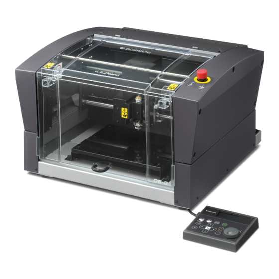
About This Machine Features of This Machine This machine is a desktop engraving machine. It can be used in a variety of applications such as making personalized gifts and accessories by engraving names and creating signboards and industrial products. • Accommodates various engraving methods This machine achieves expressive, high-quality engraving of a wide range of types, from contouring and fill, to hollowing and scribing. -
Page 8: Part Names And Functions
Part Names and Functions Front and Interior Spindle head* * In this document, the mechanisms around the spindle unit, including the spindle motor, are called the "spindle head." Also, the rotary-axis area inside the spindle unit is called the "spindle." Part Overview To ensure safety, opening this during engraving or spindle rotation... -
Page 9: Side
Part Names and Functions Side Right Side Part Overview This switches this machine's power on or off. Power switch " P.16 “Switching the Power On or Off” Power cord connector This is for connecting a power cord. Left Side Part Overview This is for connecting a LAN cable. -
Page 10: Handy Panel
Part Names and Functions Handy Panel This is used to perform tool movement and other machine operations, and to make various settings. Close the front cover, then perform the operation of the handy panel. Display screen Menus, messages, etc. are displayed here. "... -
Page 11: Viewing The Handy Panel Screen
Part Names and Functions Viewing the Handy Panel Screen (Main screen) 012345678901234567 READY X 50.00 XYZ 100% 100% Y 30.00 Z 20.00 S 5000 Part Overview When the laser pointer function is turned on, this icon appears. When Laser pointer on/off the laser pointer function is turned on, the current values of the laser pointer are displayed on the handy panel. -
Page 12: Menu List
Menu List Main Menu Main screen Turn the [Dial] to move the cursor on the screen or change the setting values. [MENU] * Press + [MENU] to return to the main screen. " P.20 Press [MENU] to return to the [MENU] previous screen.(*) [ENTER]... -
Page 13: File Menu
Menu List File Menu Main screen [FILE] [MENU] " P.123 Origin-setting Menu Main screen [ORG.Z] [ORG.XY] READY 012345678901234567 READY ORIGIN SET XY ORIGIN SET Z Z -30.00mm " P.39 " P.100 " P.108 • Turn the [Dial] to move the cursor on the screen. •... -
Page 14: Chapter 2 Basic Operation
Chapter 2 Basic Operation Emergency Stop to Ensure Safety ....................13 How to Perform an Emergency Stop ................13 Canceling an Emergency Stop..................13 Switching the Power On or Off ....................16 Switching the Power On ....................16 Switching the Power Off ....................17 Moving the Tool .......................... -
Page 15: Emergency Stop To Ensure Safety
Emergency Stop to Ensure Safety How to Perform an Emergency Stop Procedure Press the emergency stop button. Operation stops immediately. Emergency stop button Canceling an Emergency Stop Procedure Switch off the power switch. Chapter 2 Basic Operation... - Page 16 Emergency Stop to Ensure Safety Turn the button in the direction of the arrows. The button goes up, and the emergency stop is canceled. Emergency stop button Switch on the power switch. Chapter 2 Basic Operation...
- Page 17 Emergency Stop to Ensure Safety When the screen shown below appears after approximately three seconds, press [ENTER/ PAUSE]. The spindle head moves to the left of the back of this machine (this movement at the machine's startup is called the "initial operation"). Hit [ENTER] key.
-
Page 18: Switching The Power On Or Off
Switching the Power On or Off Switching the Power On When the machine is connected to a computer, install the driver, and then turn on the power. " Setup Guide "Installing the Software" Procedure Close the front cover. Switch on the power switch. Chapter 2 Basic Operation... -
Page 19: Switching The Power Off
Switching the Power On or Off When the screen shown below appears after approximately three seconds, press [ENTER/ PAUSE]. The spindle head moves to the left of the back of this machine (this movement at the machine's startup is called the "initial operation"). Hit [ENTER] key. -
Page 20: Moving The Tool
Moving the Tool Terms of Tool Position This manual uses the following terms to indicate the position of the tool. Terms Overview These refer to the numerical values that indicate the position of the tool on each of the X/Y/Z axis. They are represented 01234567890123456 待機中... -
Page 21: Moving To The Desired Position
Moving the Tool Moving to the Desired Position When the screens shown below are displayed on the handy panel, you can move the tool manually using the [Dial] or the Movement buttons. Screens on the handy panel Main screen When setting the XY origin When setting the Z origin 012345678901234567 READY... -
Page 22: Moving To The Specified Position
Moving the Tool Moving to the Specified Position The spindle head automatically moves to the predetermined position through the operation of the handy panel. Procedure Close the front cover and press [ENTER/PAUSE]. On the main screen, press [MENU/TOP]. 012345678901234567 READY X 15.00 Y 23.00 0.00... -
Page 23: Pausing And Aborting
Pausing and Aborting Pausing and Resuming Engraving This pauses engraving through operation using the handy panel. This also makes it possible to resume engraving at the paused position after an operation such as moving the tool to check the status of the workpiece. Procedure While operation is in progress, press [ENTER/PAUSE]. - Page 24 Pausing and Aborting When Checking the Status of the Workpiece by Moving the Tool Procedure Press [MENU/TOP] several times to display the following screen. 012345678901234567 PAUSE MOVE VIEW POSITION CENTER USER ORIGIN XY Select [VIEW POSITION] using the [Dial]. Press [ENTER/PAUSE] to confirm. The tool moves to the view position at the left side of the back.
-
Page 25: Aborting Engraving
Pausing and Aborting Aborting Engraving Procedure While operation is in progress, press [ENTER/PAUSE]. The tool moves to the upper limit of the Z axis, and then rotation stops. The following window is displayed. " P. 22 "When Checking the Status of the Workpiece by Moving the Tool" 012345678901234567 PAUSE X 15.00... -
Page 26: Chapter 3 Basic Engraving Methods
Chapter 3 Basic Engraving Methods Checks and Preparation before Engraving................25 Checking the Flow of Engraving Operation ............... 25 Checking Engravable Workpieces .................. 26 Determining the Item to Create and Required Material and Tool ...... 27 Creating Engraving Data........................ 28 Step 1: Starting Dr. -
Page 27: Checks And Preparation Before Engraving
Checks and Preparation before Engraving Checking the Flow of Engraving Operation P. 25 "Checks and Preparation before Engraving" Check the conditions, material and tool required to start engraving. P. 26 "Checking Engravable Workpieces" P. 27 "Determining the Item to Create and Required Material and Tool" P. -
Page 28: Checking Engravable Workpieces
Checks and Preparation before Engraving Checking Engravable Workpieces Material • Acrylic • Modeling wax • Aluminum • Brass • Wood • Chemical wood etc. Size Size that can be stably fixed in place. On this machine, an adhesive sheet is used to fix the workpiece in place. The workpiece can be large and can stick out of the workpiece table, but you must be able to stably fix it in place. -
Page 29: Determining The Item To Create And Required Material And Tool
Checks and Preparation before Engraving Thickness The thickness must be 40 mm (1.6 in.) or less whereby the height for the tool to avoid the workpiece can be maintained during engraving. Thickness of attachable workpieces = 40 mm Workpiece table (1.6 in.) * The thickness of workpiece that can actually be engraved is restricted by the length of the installed tool, the location where the nose unit is installed and the cut-out amount, and is smaller than the range... -
Page 30: Creating Engraving Data
Step 1: Starting Dr. Engrave Plus Procedure Windows 10 Click the [Start] button. Click the [Dr. Engrave Plus] icon under [DGSHAPE Dr. Engrave Plus]. Windows 8.1 Click the [Start] screen. On the [Apps] screen, click [Dr. Engrave Plus]. Windows 7 Click the [Start] button. - Page 31 Creating Engraving Data Dr. Engrave Plus Screen Name Functional overview This runs the various functions for Dr. Engrave Plus. Menu Bar Displays frequently used functions among the functions on the menu bar. Standard tool bar Displays functions related to drawing and editing of shapes. Shape tool bar This is used to configure mainly shape settings.
-
Page 32: Step 2: Creating A Shape
Creating Engraving Data Step 2: Creating a Shape Draw a rectangle. Congraturations 30 mm (1.2 in.) 5 mm (0.2 in.) 7 mm 60 mm (2.4 in.) (0.3 in.) Procedure Click Click the start point at any location, and then drag it to the end point. Start point End point Chapter 3 Basic Engraving Methods... -
Page 33: Step 3: Loading An Image
Creating Engraving Data Enter the [Size] and [Position] in the [Shape] panel. Enter the following values. Size 30 mm (1.2 in.) 60 mm (2.4 in.) Position Reference point (lower-left corner of the shape) 5 mm (0.2 in.) 7 mm (0.3 in.) You can change or move the shape you drew to any size and position. - Page 34 Creating Engraving Data From [File Type], select "Adobe Illustrator Files." Open [the drive on which Dr. Engrave Plus is installed]* - [ProgramData] - [DGSHAPE Corporation] - [Dr. Engrave Plus] - [Sample] and select "Gift_DE3.ai." * This is most commonly the [C drive] or [D drive].
-
Page 35: Step 4: Entering Text
Creating Engraving Data Drag ■ to adjust the size. To enlarge/reduce the size with the aspect ratio fixed, hold down the [Shift] key as you drag it. Drag the image to move it to the target position. Step 4: Entering Text Enter text and determine its font, etc. - Page 36 Creating Engraving Data Click Click the text that you entered. ■ appears on the four corners of the image. Set the font, text size, etc. on the [Text] panel. Enter as follows: Position the text. Using the mouse, drag the text to move it to the target position. Chapter 3 Basic Engraving Methods...
-
Page 37: Step 5: Setting The Engraving Parameters
Creating Engraving Data MEMO You can set the text's position and slant in the [Shape] panel. Step 5: Setting the Engraving Parameters Set parameters such as the material to engrave, the tool, and the depth. Procedure Click the shape you are going to engrave. Double-click the layer on which the shape to engrave is drawn on the [Layer] panel. - Page 38 Creating Engraving Data Select the [Material] and [Tool]. • Material: Wood (Hard) • Tool: ZEC-A2025 MEMO The engraving parameters are set automatically according to the selected [Material] and [Tool]. To change the engraving parameters, click [Advanced Settings] and change the settings. "...
-
Page 39: Step 6: Saving Engraving Data
Creating Engraving Data Step 6: Saving Engraving Data Procedure Click [Save]. Specify where to save the file. Enter the file name. Click [Save]. A file with the extension *.dpd is saved. Chapter 3 Basic Engraving Methods... -
Page 40: Starting Engraving
MEMO On this machine, you can use the optional center vise and T-slot table to secure the workpiece in place. For details on these optional items, contact your authorized DGSHAPE Corporation dealer or access our website (http://www. dgshape.com/). Chapter 3 Basic Engraving Methods... -
Page 41: Step 2: Setting The Xy Origin
Starting Engraving Step 2: Setting the XY Origin Set the X- and Y-axis coordinates, which will be the origin point of engraving. This position is called the "XY origin." On this machine, you can set the XY origin in any position within the operating range. Set this to match the engraving data and workpiece mounting position. - Page 42 Starting Engraving Using the [Dial], select [XY] for the target axis. 012345678901234567 READY ORIGIN SET XY Target axis XY X Y X 38.88mm The machine coordinate is displayed. Y 17.00mm MEMO You can set the origins of the X and Y axes separately by selecting [X] or [Y] for the target axis. Press [ENTER/PAUSE].
-
Page 43: Step 3: Installing A Character Cutter/Parallel Cutter
Starting Engraving Step 3: Installing a Character Cutter/Parallel Cutter Use the nose unit when engraving using a character cutter or parallel cutter. " P. 83 "Nose Unit Overview and Precautions" WARNING Never inadvertently touch the computer or handy panel while performing this task. Unintended operation of the machine may lead to you being caught in the machine. - Page 44 Starting Engraving Make the settings for Z-axis control. If the front cover is open, close it. Press [ENTER/PAUSE]. When the initial operation is complete, the main screen appears. Press [MENU] several times to display the following screen. 012345678901234567 READY SETTINGS OPERATING MODE SPINDLE REVOLUTION AUTO Z CONTROL...
- Page 45 Starting Engraving Install the cutter holder, solid collet, and nose unit. Open the front cover. Detach the cutter holder from the cutter. Hexagonal screwdriver Loosen Cutter holder Install the cutter holder on the spindle unit. While holding the spindle unit immobile with a wrench, tighten the cutter holder. The cutter holder is reverse-threaded (that is, you turn it counterclockwise to tighten it).
- Page 46 Starting Engraving Temporarily tighten the solid collet. Insert the solid collet into the spindle unit from below while holding the spindle unit immobile with a wrench, and tighten temporarily. Wrench Spindle unit Solid collet Fully tighten the solid collet. Using two wrenches, fully tighten the solid collet. Wrench Wrench Assemble the nose unit.
- Page 47 Starting Engraving Attach the nose unit to this machine. Tighten until it does not move, and then loosen about two rotations and set the scale to "0." Turn here Loosen Tighten Set the lock lever. Set the lock lever at position.
- Page 48 Starting Engraving Press [ ], [ ], [ ], and [ ] to move the spindle head to the area above the workpiece. Press [-Z] to lower the spindle head. When the tip of the nose unit touches the workpiece, descent automatically stops. Workpiece Open the front cover.
- Page 49 Starting Engraving Point: If cutter insertion is difficult If the cutter catches on the solid collet and is difficult to insert, loosening the cutter holder makes insertion easier. Note that inserting it forcibly may result in damage to the workpiece. After inserting the cutter, tighten the cutter holder again.
- Page 50 Starting Engraving Set the engraving depth. Adjust the amount of extension of the cutter after raising the cutter to prevent the workpiece from being scratched. Close the front cover and press [ENTER/PAUSE]. Press [ +Z] to move the cutter to the upper limit of the z-axis. Open the front cover.
- Page 51 Starting Engraving Slowly move the spindle head by hand to the back of the workpiece table on the right side. Be careful not to apply strong impact. Pass the end of the dust collection hose ("hose") from the front to the back of this machine.
- Page 52 Starting Engraving Slowly move the spindle head by hand to the front left. Be careful not to apply strong impact. Fasten the hose with the (two) clamps in the center of this machine. Clamp Clamp Retaining band Attach the vacuum adapter to the nose unit. Secure the vacuum adapter while pressing it against the top.
-
Page 53: Step 4: Checking The Engraving Parameters
Starting Engraving Attach the adapter to the hose on the back of this machine. Hose Adapter Attach a vacuum cleaner to the end of the adapter on the back. Close the front cover. Press [ENTER/PAUSE]. " P. 58 "Before using the vacuum adapter, be sure to verify the following points" Step 4: Checking the Engraving Parameters Start Dr. - Page 54 Starting Engraving Click the shape you want to check the engraving parameters for. Double-click the layer on which the shape to engrave is drawn on the [Layer] panel. Check the engraving parameters. Click [Engraving Parameters]. * Because the automatic Z control feature is used, there is no need to set the [Depth]. Check the [Material] and [Tool] that have been set.
- Page 55 Starting Engraving Click [Advanced Settings] and check the settings. Set the items as required. " P. 96 "Detailed Settings on the [Engraving Parameters] Screen" Click [OK]. The [Engraving Parameters] screen closes. Click [OK]. Open the front cover. Chapter 3 Basic Engraving Methods...
-
Page 56: Step 5: Starting Engraving
Starting Engraving Check the scale of the nose unit. Confirm that the scale of the nose unit is set to the desired engraving depth. The amount of extension of the cutter is the engraving depth. 4 scale ticks = Approx. 0.1 mm (0.004 in.) 1 scale tick = 0.0254 mm (0.001 in.) - Page 57 Starting Engraving Click [Engrave]. The [Engrave] screen appears. Select [DGSHAPE DE-3] for the [Printer Name]. Click [OK]. The engraving data is sent to the machine. When the following screen is displayed on the panel of this machine, select [Start]. 012345678901234567 PAUSE Data received.
-
Page 58: Other Basic Operations
Other Basic Operations Adjusting the Tool Feeding Speed and the Number of Rotations during Engraving (Override) You adjust the engraving parameters by specifying the ratio of change relative to the present feeding speed and spindle rotating speed. This feature is called "override." An override is possible only within the range of this machine's settable feeding speed and spindle rotating speed. - Page 59 Other Basic Operations Press [ENTER/PAUSE]. Select the change ratios using the [Dial]. Press [ENTER/PAUSE] to confirm. Press [MENU/TOP]. The main screen in the paused state appears again. 012345678901234567 PAUSE X 15.00 XYZ 100% 100% Y 23.00 0.00 S 5000 Press [ENTER/PAUSE]. 012345678901234567 PAUSE Resume cutting?
-
Page 60: Attaching The Vacuum Adapter
Other Basic Operations Attaching the Vacuum Adapter This lets you perform engraving while taking up cutting waste using a vacuum cleaner with the vacuum adapter attached. This can minimize scattering of cutting waste. WARNING When using a vacuum cleaner to take up cutting waste, exercise caution to prevent fire or dust explosion. - Page 61 Other Basic Operations Procedure Turn off this machine. Open the front cover. Slowly move the spindle head by hand to the back of the workpiece table on the right side. Be careful not to apply strong impact. Pass the end of the dust collection hose ("hose") from the front to the back of this machine.
- Page 62 Other Basic Operations Fasten the hose with the clamp close to the back of this machine. Fasten at the position of the retaining band on the hose. Front Clamp Workpiece table Hose MEMO Opening the clamp Closing the clamp Fasten at the position where you hear a "click."...
- Page 63 Other Basic Operations Attach the vacuum adapter to the nose unit. Secure the vacuum adapter while pressing it against the top. Point 1: Attach it so that it is level. Good Not Good Screw Point 2: Tighten so that the notch is on the front. Attach from below Notch Failing to do so may lead to the...
-
Page 64: Setting The Lock Lever
Other Basic Operations Setting the Lock Lever You change the position at which the lock lever is set to match the setting for automatic Z control. • When [AUTO Z CONTROL] is set to [ON], you set the lock lever at one of these positions. The spindle head is put into a floating state, and the Z-axis origin point is determined by the height of the workpiece surface. -
Page 65: Changing The Operation Mode
Other Basic Operations Changing the Operation Mode This selects the operation when engraving data is sent from the computer. Procedure If the front cover is open, close it. Press [ENTER/PAUSE]. Press [MENU] several times to display the following screen. 012345678901234567 READY SETTINGS OPERATING MODE... -
Page 66: Setting The Avoidance Height Of The Tool To Match The Workpiece Shape
Other Basic Operations Setting the Avoidance Height of the Tool to Match the Workpiece Shape When moving to another engraving area, the tool first avoids the workpiece in the upward direction, and then moves along the X and Y axes. Make the setting for this avoidance height. * This setting is enabled when [AUTO Z CONTROL] is set to [ON]. - Page 67 Other Basic Operations Turn the [Dial] and set the avoidance height. For the setting value, set the distance from Z user origin. If the difference in level is above the origin, specify the setting value that exceeds the difference in level. 012345678901234567 READY AUTO Z SETTING...
-
Page 68: Chapter 4 Maintenance
Chapter 4 Maintenance Maintenance Precautions ......................67 Daily Care ............................68 Cleaning after Engraving Finishes .................. 68 Cleaning Inside the Spindle Unit Cover ............... 69 Storing the Cutter ......................... 70 Replacing Consumable Parts ....................... 71 Replacing the Spindle Unit ....................71 Replacing the Resin Nose Cone .................. -
Page 69: Maintenance Precautions
Maintenance Precautions WARNING Perform this task with all power switches left switched off. Otherwise sudden movement of the machine may cause injury. WARNING Never use a pneumatic blower. This machine is not compatible with a pneumatic blower. Cutting waste may get inside the machine and cause fire or electrical shock. -
Page 70: Daily Care
Daily Care Cleaning after Engraving Finishes Cleaning Inside the Front Cover Open the front cover and clean away any buildup of cutting waste inside. Never touch these rails. Attaching the Workpiece Table After removing the workpiece table and cleaning it, exercise caution regarding the positions of the tabs, orienting them as shown in the figure when attaching the workpiece table. -
Page 71: Cleaning Inside The Spindle Unit Cover
Daily Care Cleaning Near the Spindle Head Uninstall the nose unit, collet, and tool, and remove any cutting waste that has collected in areas such as the tip of the spindle unit and the laser pointer. Spindle unit Laser pointer Cleaning Inside the Spindle Unit Cover Detach the spindle unit cover and clean away any buildup of cutting waste inside. -
Page 72: Storing The Cutter
Daily Care Storing the Cutter For repeated use while keeping the amount of extension of the cutter tip constant, we recommend that you remove the cutter holder and cutter from the spindle unit without separating them from one another once you have determined the amount of extension. -
Page 73: Replacing Consumable Parts
Replacing Consumable Parts CAUTION Remove the cutting tool before performing replacement work. Contact with the blade may result in injury. Replacing the Spindle Unit The spindle unit and the belt are consumable parts. For information on how to perform replacement, refer to the documentation included with the ZS-35S replacement spindle unit. - Page 74 Replacing Consumable Parts Hold down and press [MENU/TOP]. The main screen appears again. 012345678901234567 READY X 15.00 Y 23.00 0.00 S 5000 Resetting the Working Time after Replacing the Spindle After replacing the spindle, reset the working time. Procedure Press [MENU/TOP] several times to display the following menu. 012345678901234567 READY SETTINGS...
-
Page 75: Replacing The Resin Nose Cone
Replacing Consumable Parts Press [ENTER/PAUSE]. The working time of the spindle is reset. Replacing the Resin Nose Cone The resin nose cone is a consumable part. It wears out as you continue to perform engraving. Replace it at the appropriate time. Checking the Replacement Time The resin nose cone should be replaced when it becomes worn to the protrusion as shown in the figure. - Page 76 Replacing Consumable Parts Remove the nose unit from this machine. Turn here Loosen Loosen and remove the ring. Ring Replace the nose cone with a new one. Nose cone Tighten the ring. Ring Chapter 4 Maintenance...
-
Page 77: Correction
Correction Distance Correction Important These settings affect the engraving accuracy. Set these values with great care. We do not recommend the operation if you are not confident about the settings. The distance correction for the X-axis and Y-axis can be set. 012345678901234567 READY DISTANCE CORRECTION... - Page 78 Correction Close the front cover. Press [ENTER/PAUSE]. The main screen is displayed. Press [+Z] to raise the tool. Press [ ], [ ], [ ], and [ ] to move the tool to a position on the workpiece. Press [ORG.XY/POINTER]. Using the [Dial], select [XY] for the target axis.
- Page 79 Correction Press [ ], [ ], [ ], and [ ] to move the laser pointer to the position marked in step Write down the XY coordinates displayed on the main screen. Set the correction values. Press [MENU/TOP] several times to display the following menu. 012345678901234567 READY SETTINGS...
-
Page 80: When Moving The Machine
When Moving the Machine When moving the machine, attach the retainers to protect it from impact during movement. Avoid touching the rails while performing work Needlessly touching the rails will remove their grease, leading to the rails rusting. Rail Procedure Make sure the machine is not in operation, then turn off the power switch. - Page 81 When Moving the Machine Attach retainers B and C. Hexagonal Retainer B Hexagonal Retainer C wrench wrench Slowly move the spindle head to the left. Be careful not to apply strong impact. Spindle head Attach retainer A. Retainer A Hexagonal wrench Chapter 4 Maintenance...
-
Page 82: When The Machine Has Not Been Used For A Prolonged Period
When the Machine Has Not Been Used for a Prolonged Period Spindle Run-in (Warm-up) Perform spindle run-in (warm-up) to stabilize the rotation of the spindle. Procedure Close the front cover. Press [ENTER/PAUSE]. On the main screen, press [SPINDLE]. The cursor moves to [S], and the spindle rotating speed can be changed. SPINDLE ON/OFF Turn the [Dial] on the handy panel until the spindle rotating speed reaches "5000 rpm."... - Page 83 When the Machine Has Not Been Used for a Prolonged Period Hold down [SPINDLE] for one second or longer. The spindle begins to rotate. Leave the spindle rotating for 15 minutes. Press [SPINDLE]. Rotation of the spindle stops. Repeat steps under the following conditions: Number of rotations Working time...
-
Page 84: Chapter 5 Various Engraving Methods
Chapter 5 Various Engraving Methods Nose Unit Overview and Precautions ..................83 The Role of the Nose Unit ....................83 Nose Unit Limitations ......................83 When Using Nose Unit ....................... 84 Using Various Tools .......................... 85 Determining the Item to Create and Required Material and Tool ...... 85 Considering Engraving Parameters ................ -
Page 85: Nose Unit Overview And Precautions
Nose Unit Overview and Precautions The Role of the Nose Unit Attaching the nose unit and setting [AUTO Z CONTROL] to [ON] enables automatic detection of the Z origin as the position where the tip of the nose unit touches the surface of the workpiece. This makes it possible to perform engraving on a workpiece of uneven surface height at a uniform depth. -
Page 86: When Using Nose Unit
Nose Unit Overview and Precautions Other Cases Where the Nose Unit Is Unsuitable • When using a diamond scraper • When using an end mill • When you do not want to attach the vacuum adapter Using the nose unit without attaching the vacuum adapter may lead to unintended engraving results. •... -
Page 87: Using Various Tools
Using Various Tools Determining the Item to Create and Required Material and Tool Procedure Check the engraving method for the item you want to create. Engraving Item to create Material Explanation method This method performs engraving while rotating the tool. Use this method to draw characters and illustrations •... - Page 88 * Optional parts may need to be purchased depending on the type and diameter of the tool. Contact your authorized DGSHAPE Corporation dealer or access our website (http://www.dgshape.com/) to purchase the optional tool or dedicated collet. Check the tool installation method.
-
Page 89: Considering Engraving Parameters
Using Various Tools Considering Engraving Parameters This machine lets you perform engraving using a wide variety of workpiece materials and tools. However, the optimal engraving conditions that yield the desired engraving results for these combinations vary. Typical Setting by Material The table below shows suggested tools and engraving parameters suited to various types of workpieces. -
Page 90: Using A Diamond Scraper
Using Various Tools Using a Diamond Scraper This performs "Scribing" using a diamond scraper. With "Scribing," cutting is carried out by scraping the workpiece without rotating the spindle. Because automatic Z control is set to [ON], the cutting-in depth of the workpiece is determined by the pressure of the cutter. - Page 91 Using Various Tools Press [ENTER/PAUSE]. Set the spindle rotation to "OFF." Press [MENU/TOP] several times to display the following menu. 012345678901234567 READY SETTINGS OPERATING MODE SPINDLE REVOLUTION AUTO Z CONTROL Turn the [Dial] and select [SPINDLE REVOLUTION]. Press [ENTER/PAUSE]. Turn the [Dial] and select [OFF]. 012345678901234567 READY SETTINGS...
- Page 92 Using Various Tools Press [MENU/TOP]. The main screen appears again. The Z-axis coordinate display changes to [AUTO], and the spindle rotating speed display changes to [OFF]. X 15.00 Y 39.00 AUTO S 5000 Install the cutter holder and solid collet. Open the front cover.
- Page 93 Using Various Tools Attach a solid collet that fits the diameter of the cutter. There are two types of solid collets. For ø4.36 mm (0.17 in.) diamond scrapers, use an optionally available dedicated diamond-scraper collet. Dedicated for ø4.36 mm (0.17 in.) diamond scraper For ø3.175 mm (0.125 in.) (Optional item) Temporarily tighten the solid collet.
- Page 94 Using Various Tools Set the lock lever. Set the lock lever at position. For details on the setting position of the lock lever, see the following page. " P. 62 "Setting the Lock Lever" Lock lever Press slightly, then lower it. Install the diamond scraper and determine the amount of extension.
- Page 95 Using Various Tools Secure the diamond scraper in place where the tip is extended by about 10 mm (0.4 in.). Tighten the mounting screw for the cutter holder. Cutter holder Hexagonal screwdriver Mounting screw Diamond scraper Approximately 10 mm (0.4 in.) This completes the installation of the diamond scraper.
- Page 96 Using Various Tools Setting the Engraving Parameters Procedure Start Dr. Engrave Plus. If engraving data is already opened, proceed to step Click [Open]. Select the data to engrave. Click [Open]. Click the shape you are going to engrave. Double-click the layer on which the shape to engrave is drawn on the [Layer] panel. Chapter 5 Various Engraving Methods...
- Page 97 Using Various Tools Set each condition. Click [Engraving Parameters]. * Because the automatic Z control feature is used, there is no need to set the [Depth]. Set the [Material] and [Tool]. When you select a diamond scraper (ZDC-A2000 or ZDC-A4000), the [Scribe] check box is selected.
- Page 98 Using Various Tools Click [OK]. The [Engraving Parameters] screen closes. Click [OK]. " P. 54 "Step 5: Starting Engraving" Detailed Settings on the [Engraving Parameters] Screen Detailed settings Explanation This sets the speed at which the tool moves along X/Y axis during engraving. XY Speed Unit: mm/sec.
-
Page 99: Using An End Mill
Using Various Tools Using an End Mill This performs engraving using an end mill. WARNING Never inadvertently touch the computer or handy panel while performing this task. Unintended operation of the machine may lead to you being caught in the machine. WARNING Securely fasten the cutting tool and workpiece in place. - Page 100 Using Various Tools Turn the [Dial] and select [AUTO Z CONTROL]. Press [ENTER/PAUSE]. Turn the [Dial] and select [OFF]. * The engraving depth varies according to the engraving data created using Dr. Engrave Plus. 012345678901234567 READY SETTINGS OPERATING MODE SPINDLE REVOLUTION AUTO Z CONTROL Press [ENTER/PAUSE] to confirm.
- Page 101 Using Various Tools Install the collet with the attached end mill. Temporarily tighten the collet with end mill. Insert the collet with end mill into the spindle unit from below, then, while holding the spindle unit immobile with a wrench, tighten temporarily. Wrench Spindle unit Collet with an end mill...
- Page 102 Using Various Tools Set the Z origin. Close the front cover. Press [ENTER/PAUSE]. Press [ ], [ ], [ ], and [ ] to move the end mill to the area above the workpiece. Next, perform a small amount of cutting into the workpiece. Move to a location where cutting will not cause any problems.
- Page 103 Using Various Tools Press [SPINDLE]. The spindle stops. SPINDLE ON/OFF Press [ORG.Z]. Press [ENTER/PAUSE]. 012345678901234567 READY ORIGIN SET Z Z -30.00mm The machine coordinate is displayed. The main screen appears again. The coordinate value for Z-axis is set to "0," and the current value is set to Z0.
- Page 104 Using Various Tools Setting the Engraving Parameters Procedure Start Dr. Engrave Plus. If engraving data is already opened, proceed to step Click [Open]. Select the data to engrave. Click [Open]. Click the shape you are going to engrave. Double-click the layer on which the shape to engrave is drawn on the [Layer] panel. Chapter 5 Various Engraving Methods...
- Page 105 Using Various Tools Set each condition. Set the [Depth]. Click [Engraving Parameters]. Set the [Material] and [Tool]. Confirm that the [Scribe] check box is cleared. Click [Advanced Settings]. Set each item according to the engraving conditions. " P. 96 "Detailed Settings on the [Engraving Parameters] Screen" Chapter 5 Various Engraving Methods...
-
Page 106: Using A Character Cutter/Parallel Cutter (Without Nose Unit)
Using Various Tools Click [OK]. The [Engraving Parameters] screen closes. Click [OK]. " P. 54 "Step 5: Starting Engraving" Using a Character Cutter/Parallel Cutter (without Nose Unit) Perform engraving without using the nose unit in the following situations: ¾ When you do not want to attach the vacuum adapter ¾... - Page 107 Using Various Tools Items used in this procedure Character cutter Hexagonal Solid collet* Wrenches (2) screwdriver parallel cutter* * Optional item ** There are two types of solid collets. Use a solid collet that fits the diameter of the cutter that will be used. The collet for ø4.36 cutters is an optional item.
- Page 108 Using Various Tools Press [ENTER/PAUSE]. Turn the [Dial] and select [OFF]. * The engraving depth varies according to the engraving data created using Dr. Engrave Plus. " P. 35 "Step 5: Setting the Engraving Parameters" 012345678901234567 READY SETTINGS OPERATING MODE SPINDLE REVOLUTION AUTO Z CONTROL Press [ENTER/PAUSE] to confirm.
- Page 109 Using Various Tools Install the cutter holder. While holding the spindle unit immobile with a wrench, tighten the cutter holder. The cutter holder is reverse-threaded (that is, you turn it counterclockwise to tighten it). Be careful to turn it in the correct direction. Turn counterclockwise Wrench Cutter holder...
- Page 110 Using Various Tools Fully tighten the solid collet. Using two wrenches, fully tighten the solid collet. Wrench Wrench Set the lock lever. Set the lock lever at position. The spindle head is secured in place. " P. 62 "Setting the Lock Lever" Lock lever Lift up.
- Page 111 Using Various Tools Press [-Z] to lower the spindle head. Stop at a position where the tip of the solid collet is approximately 10 mm (0.4 in.) away from the surface of the workpiece. Solid collet Approximately 10 mm Workpiece (0.4 in.) Press [ORG.Z].
- Page 112 Using Various Tools Insert the cutter into the cutter holder and bring the tip of the cutter into contact with the surface of the workpiece. Placing a thin sheet of paper on the workpiece can prevent damage to the workpiece when the cutter touches it.
- Page 113 Using Various Tools Secure the cutter in place. Tighten the mounting screw for the cutter holder. Cutter holder Mounting screw Hexagonal screwdriver Close the front cover. Press [ENTER/PAUSE]. This completes the installation of the cutter. Setting the Engraving Parameters Procedure Start Dr.
- Page 114 Using Various Tools Select the data to engrave. Click [Open]. Click the shape you are going to engrave. Double-click the layer on which the shape to engrave is drawn on the [Layer] panel. Set each condition. Enter the [Depth]. Click [Engraving Parameters]. Chapter 5 Various Engraving Methods...
- Page 115 Using Various Tools Set the [Material] and [Tool]. Confirm that the [Scribe] check box is cleared. Click [Advanced Settings]. Set each item according to the engraving conditions. " P. 96 "Detailed Settings on the [Engraving Parameters] Screen" Click [OK]. The [Engraving Parameters] screen closes. Click [OK].
-
Page 116: Surface Leveling Of The Workpiece Table
Surface Leveling of the Workpiece Table Products can be finished with higher quality by obtaining flatness by cutting the workpiece table surface to a uniform depth. This operation of obtaining flatness is called "surface leveling." It is performed when rigorously precise flatness is required, such as for plate engraving, which is performed without using the nose unit. - Page 117 Surface Leveling of the Workpiece Table Press [ENTER/PAUSE]. The spindle head moves to the machine origin. Press [MENU/TOP] several times to display the main screen. 012345678901234567 READY X 51.00 Y 37.00 0.00 S 5000 Press [ORG.XY/POINTER]. Using the [Dial], select [XY] for the target axis. 012345678901234567 READY ORIGIN SET XY...
- Page 118 Execute the engraving data for surface leveling. Start Dr. Engrave Plus. Click [Open]. Open [the drive on which Dr. Engrave Plus is installed]* - [ProgramData] - [DGSHAPE Corporation] - [Dr. Engrave Plus] - [Sample]. * This is most commonly the [C drive] or [D drive].
- Page 119 Surface Leveling of the Workpiece Table Check visually to ensure that no uncut areas remain. If any parts have not been cut, redo the operation from P. 115 "2. Install the parallel cutter and set the Z origin.". MEMO The initial values for the engraving parameters in the surface leveling data are shown below. Generally, we recommend that you do not change these settings.
-
Page 120: Previewing Before Engraving
Previewing before Engraving Preview using the laser pointer. " P. 155 "Laser Pointer Irradiation Area" Checking the Cutting Path of the Tool (Path Preview) The laser pointer traces the path that the tool takes to engrave the shape. Verify that the laser pointer passes through the intended area of the loaded workpiece. -
Page 121: Checking The Four Corners Of The Engraving Area (Area Preview)
Previewing before Engraving Click [File] - [Engraving Preview]. On the [Engraving Preview] screen, select [Outline of All Shapes]. This starts the path preview. Checking the Four Corners of the Engraving Area (Area Preview) The laser pointer pauses at the points of four corners of the engraving area to indicate the area. Verify that the laser pointer stops within the intended area of the loaded workpiece. - Page 122 Previewing before Engraving Select the data to engrave. Click [Open]. Click [File] - [Engraving Preview]. On the [Engraving Preview] screen, select [Corner of Drawing Area]. Turn the [Dial] and select the corner to preview. 012345678901234567 READY PREVIEW AREA Left-Front Right-Front Right-Rear Press [ENTER/PAUSE].
-
Page 123: Checking Any Point On Engraving Data Using A Workpiece (Point Preview)
Previewing before Engraving Checking Any Point on Engraving Data Using a Workpiece (Point Preview) Procedure Set the workpiece. " P. 38 "Setting the Workpiece" Close the front cover. Press [ENTER/PAUSE]. Start Dr. Engrave Plus. If engraving data is already open, proceed to step Click [Open]. - Page 124 Previewing before Engraving Move the laser pointer to any position. Right-click any point on the main screen. Click [Move LP Here]. Right-click The laser pointer turns on and moves to the position you have clicked on the screen. Chapter 5 Various Engraving Methods...
-
Page 125: Repeating The Same Engraving
Repeating the Same Engraving The data sent from the computer is saved in this machine's memory. You can repeatedly perform the same engraving just by using this data and performing operations from this machine. Procedure Send engraving data from the computer, and perform engraving. Replace the workpiece. -
Page 126: Things You Can Do When Creating Engraving Data
Things You Can Do When Creating Engraving Data Making Use of Layers Just like a celluloid picture, different shapes can be created on each layer. These multiple shapes can then be overlaid and certain shapes can be hidden to create an overall design. Draw on each layer When all layers are displayed Layer 1... -
Page 127: Chapter 6 Appendix
Chapter 6 Appendix Troubleshooting (Machine Problems) ..................126 The Power Does Not Turn On ..................126 Initial Operations Are Not Performed or Fail ............126 The Operation Button Does Not Respond When Pushed ........126 The USB Cable/LAN Cable Has Come Loose during Engraving ......126 The Machine Does Not Move When Engraving Data Is Sent ......127 The Spindle rotates but Does Not Move From Its Position When Engraving Data Is Sent ..................127... -
Page 128: Troubleshooting (Machine Problems)
Troubleshooting (Machine Problems) The Power Does Not Turn On Check Action Has the emergency stop button been Pressing the emergency stop button automatically turns off the power. pressed? Release the emergency stop button. " P. 13 “Canceling an Emergency Stop” Initial Operations Are Not Performed or Fail Check Action... -
Page 129: The Machine Does Not Move When Engraving Data Is Sent
Troubleshooting (Machine Problems) The Machine Does Not Move When Engraving Data Is Sent Check Action Is the cable connecting the computer Connect the cable securely. and this machine connected? " Setup Guide Is the front cover open? Close the front cover, and then press [ENTER/PAUSE]. Is operation paused? When the machine is paused, engraving stops and some operations are restricted. -
Page 130: Descent Does Not Stop
Troubleshooting (Machine Problems) Check Action Has the [ZDC-A2000] or [ZDC-A4000] When you select a diamond scraper, the [Scribe] check box is selected diamond scraper been selected for automatically, and the spindle does not rotate so as to perform scribing [Tool] on the [Engraving Parameters] for the engraving. -
Page 131: Loud Noise Or Unpleasant Noise During Engraving
Troubleshooting (Machine Problems) Loud Noise or Unpleasant Noise during Engraving Check Action The load applied to the tool may be too Make adjustments, such as reducing the feeding speed or engraving large. depth. " P. 96 “Detailed Settings on the [Engraving Parameters] Screen” "... -
Page 132: Troubleshooting (Engraving Quality Problems)
Troubleshooting (Engraving Quality Problems) Engraving Is Not Performed on the Expected Position You can use the preview function to check the engraving position in advance. " P. 118 "Previewing before Engraving" Check Action Have the origins been set at correct Check that the origins have been set correctly. -
Page 133: The Tool Leaves Tracks At Places Where Cutting-In Starts Or Where Lines Change Direction
Troubleshooting (Engraving Quality Problems) The Tool Leaves Tracks at Places Where Cutting-in Starts or Where Lines Change Direction Check Action Is the spindle rotating speed too fast for Try reducing the spindle rotating speed. the feeding speed? " P. 56 “Adjusting the Tool Feeding Speed and the Number of Rotations during Engraving (Override)”... -
Page 134: Engraved Lines Are Uneven Or Wavy
Troubleshooting (Engraving Quality Problems) Engraved Lines Are Uneven or Wavy Check Action Is the cutter holder, the cutter holder If the parts around the tool are loose, the tool goes out of control. Tighten mounting screw, or the collet loose? securely. -
Page 135: Troubleshooting (Installation)
Troubleshooting (Installation) Driver Installation Is Impossible If installation quits partway through or if the wizard does not appear when connecting with a USB cable, Engraver Driver may not have been installed correctly. In such cases, perform the following procedures. (If procedure A does not solve your problem, perform procedure B.) Windows 10 (Procedure A) Procedure... - Page 136 Troubleshooting (Installation) If the [User Account Control] window appears, click [Continue]. [Device Manager] appears. From the [View] menu, click [Show hidden devices]. In the list, find and double-click [Printers] or [Other devices]. The name of your machine or [Unknown device] appears below the selected item. Click the name to select it.
- Page 137 Troubleshooting (Installation) Windows 8.1 (Procedure B) Procedure Connect the machine to the computer using the USB cable. Turn on the machine. If [Found New Hardware] appears, click [Cancel]. If any printers other than the machine are connected to the computer, disconnect their USB cables.
- Page 138 Troubleshooting (Installation) Check that the model you are using is displayed under "Unspecified." Right-click the icon of the model you are using, and then click [Troubleshoot]. When a window is displayed with the message [Install a driver for this device], click [Apply this fix].
-
Page 139: Uninstalling The Driver
Troubleshooting (Installation) Uninstalling the Driver To uninstall Engraver Driver, follow the procedure below. Important When you uninstall the driver, the driver for the USB connection and the driver for the LAN connection will both be deleted regardless of which connection method you are using. Windows 10 * If you uninstall the driver without following the procedure given below, you may not be able to reinstall the driver. - Page 140 D: \Drivers\WINX64 (64-bit versions) D: \Drivers\WINX86 (32-bit versions) If you're not using the DGSHAPE Software Package CD, go to the DGSHAPE Corporation website (http:// www.dgshape.com/) and download Engraver Driver for the machine you want to remove, and then specify the folder where the downloaded file has been extracted.
- Page 141 D: \Drivers\WINX64 (64-bit versions) D: \Drivers\WINX86 (32-bit versions) If you're not using the DGSHAPE Software Package CD, go to the DGSHAPE Corporation website (http:// www.dgshape.com/) and download Engraver Driver for the machine you want to remove, and then specify the folder where the downloaded file has been extracted.
-
Page 142: Installing The Driver Separately
Procedure Log on to Windows as the computer's administrator (or as an "Administrators" account). Insert the DGSHAPE Software Package CD into the CD-ROM drive of the computer. When the automatic playback window appears, click [Run menu.exe]. The setup menu appears automatically. - Page 143 Troubleshooting (Installation) Select [Install], [DGSHAPE DE-3] for the model name, the port, and then click [Start]. Select the [Port] according to the method for connecting this machine and the computer. Engraver Driver installation begins. Follow the on-screen explanations to proceed with the installation.
-
Page 144: Installing The Software And The Electronic-Format Manual Separately
Procedure Log on to Windows as the computer's administrator (or as an "Administrators" account). Insert the DGSHAPE Software Package CD into the CD-ROM drive of the computer. When the automatic playback window appears, click [Run menu.exe]. The setup menu appears automatically. - Page 145 Troubleshooting (Installation) Follow the on-screen instructions to proceed with the installation. If the [User Account Control] window appears, click [Allow], and then continue with the installation. When the installation finishes, click on the setup menu. Remove the CD from the CD-ROM drive. Chapter 6 Appendix...
-
Page 146: Responding To An Error Message
Responding to an Error Message This section describes the error messages that may appear on the handy panel screen of this machine, and how to take action to remedy the problem. If the action described here does not correct the problem or if an error message not described here appears, contact your authorized Roland DG Corporation dealer. -
Page 147: 1000-000*" The % Limit Switch Was Not Found
Responding to an Error Message "1000-000*" The % limit switch was not found. * The name of the axis (X, Y, Z, or a combination of these axes) is displayed for %. L e v el 3 • 1000-0001: X axis •... -
Page 148: 1023-0000" (Rml-1) The Number Of The Parameters Is Incorrect
Responding to an Error Message "1023-0000" (RML-1) The number of the parameters is incorrect. L e ve l 1 Error Situation/Cause • There is a problem with the engraving data received from the computer. • The data transfer has failed due to the computer being under a high load. Action Procedure Turn the [Dial] and select [Continue] or [CancelJob]. -
Page 149: 1025-0000" (Rml-1) A Wrong Command Is Detected
Responding to an Error Message When Using Software Other Than Dr. Engrave Plus Contact the software manufacturer to check whether the software is compatible with this machine. "1025-0000" (RML-1) A wrong command is detected. L e v el 1 Error Situation/Cause •... -
Page 150: "102A-000*" The Spindle Experienced Overcurrent
Responding to an Error Message Action Procedure Turn off the power. Turn on the power. Press [ENTER/PAUSE]. Review the tool, workpiece, or engraving parameters. " P. 87 "Considering Engraving Parameters" Set the Z origin. " P. 108 "4. Install the cutter and set the Z origin point." If the Error Occurs Again There is a possibility that the spindle unit is defective. -
Page 151: "102B-0000" The Spindle Motor Temperature Is Too High
Responding to an Error Message If the Error Occurs Again There is a possibility that the spindle unit is defective. To replace the spindle unit, contact your authorized Roland DG Corporation dealer. "102B-0000" The spindle motor temperature is too high. L e v el 2 Error Situation/Cause •... -
Page 152: "102D-0000" The Spindle Cannot Be Turned
Responding to an Error Message "102D-0000" The spindle cannot be turned. L e ve l 3 Error Situation/Cause The spindle failed to reach the specified number of rotations. Action Procedure Turn off the power. Turn on the power. Press [ENTER/PAUSE]. Resume operation. -
Page 153: Locations Of The Power Rating And Serial Number Labels
Locations of the Power Rating and Serial Number Labels Serial number The serial number is required for maintenance, servicing, and support. Never peel off the label. Power rating Use an electrical outlet that meets the requirements for voltage and frequency given here. -
Page 154: Connector Specifications
Connector Specifications Expansion Port +24 V Adaptive plug 9 mm max = 375 mA Pin 1 Pin 2 4.7 Ω Connector This circuit works during spindle motor rotation. * We are not responsible for machines connected to this port. Important •... -
Page 155: Machine Specifications
Machine Specifications External View Unit: mm Chapter 6 Appendix... -
Page 156: Work Area
Machine Specifications Work Area XY Operating Range 6×Φ3.5凵Φ8 2×Φ3.1 Y operating range /Workpiece table dimensions 2×Φ3.1 X operating range/Workpiece table dimensions Unit: mm Z Operating Range Z operating Workpiece table range Unit: mm * The thickness of workpiece that can actually be engraved is restricted by the length of the installed tool, the location where the nose unit is installed and the cut-out amount, and is smaller than the range indicated above. -
Page 157: Workpiece Table Installation Area Dimensional Drawing
Machine Specifications Workpiece Table Installation Area Dimensional Drawing 21×M5 Unit: mm 4×M4 Laser Pointer Irradiation Area Laser pointer Y operating range irradiation area /Workpiece table dimensions ( 260 mm ) X operating range/Workpiece table dimensions Unit: mm Chapter 6 Appendix... -
Page 158: Main Specifications
(retaining screw, spring), spare tool retaining screw (for the cutter holder), character cutter (ø3.175 mm (0.125 in.)), solid collet (ø3.175 mm (0.125 in.)), wrench, hexagonal wrench, hexagonal screwdriver, adhesive sheet, vacuum adapter, DGSHAPE Software Package CD, and Setup Guide Chapter 6 Appendix... - Page 159 FA01384 R1-181210...
Need help?
Do you have a question about the DE-3 and is the answer not in the manual?
Questions and answers