
Subscribe to Our Youtube Channel
Summary of Contents for WorkSmart JE Series
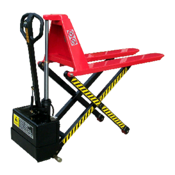
- Page 1 Instruction Manual ELECTRIC HIGH LIFT TRUCK Note: Owner/Operator must read and understand this instruction manual before using the electric high lift truck.
-
Page 2: Brief Introduction
The mechanical part of the JE series consists mainly of a fork, lifting yoke, lifting bar, cylinder, handle, etc. Its power part mainly includes a battery, mini-pump station, high-pressure hose, fuse, control switch, etc. -
Page 3: Specifications
Specifications WS-MH-LFTB WS-MH-LFTB WS-MH-LFTB WS-MH-LFTB Model 1-114 1-116 1-115 1-117 Rated Capacity (lb) 2200 3300 Max. Lifting Height (in) 31.5 Min. Fork Height (in) Fork Length (in) 44.9 43.3 Fork Overall Width (in) 20.5 26.7 20.5 26.7 Φ2.95×1.97 Dia. of Front Wheel (in) Φ5.9×1.57 Dia. -
Page 4: Operation
1. JE truck lift series are designed for working on flat and even ground. 2. The handle (102) should only be used for pulling and steering. 3. When the fork is lifted to its highest position, the JE series lift truck should not be moved. - Page 5 2. Raise the fork to its full range 1 to 2 times before use to release the air in the hydraulic system. 3. JE series truck lifts are prohibited to lift or pull personnel. The JE series truck lifts are prohibited from operation on a sloped surface.
-
Page 6: Problems And Maintenance
Problems and Maintenance Symptom Cause Remedy 1. Switch is out of order 1. Check switch (197) Fork does not 2. Fuse is broken 2. Replace fuse (277) ascend when 3. Magnetic switch is out 3. Check magnetic activating of order switch (224) up-button 4. - Page 7 HYDRAULIC CIRCUIT / ELECTRIC WIRING DIAGRAM...
- Page 8 EXPANDED FIGURE & PARTS LIST Item No. Description Fork Screw Power Unit Hold Yoke Wheel Yoke...
- Page 9 Centrifugal Axle Spacer Steering Wheel Snap Ring Snap Ring Bush Bush Washer washer Ball bearing Front wheel Wheel axle Roller Bush Washer Spring washer Lock Nut Screw Steering wheel assembly (incls.6,9,10,21) Screw Ball Snap ring Bush quill bearing...
- Page 10 EXPANDED FIGURE & PARTS LIST FOR ELECTRIC CONTROL ASSEMBLY...
- Page 11 Item No. Description Power Unit Battery Terminal (+) Battery Terminal (-) Terminal Washer Screw Electric Control Case Spacer Spring Washer Screw Fuse Base Relay Relay Base Screw Relay Control Valve Oil Tank Control Valve Pump Station Assembly Switch Socket Fuse Box Magnet Magnet Recharger Socket...
- Page 12 Screw Moving Plate Cover Switch Volt Meter Washer Battery ,12V/80Ah Cover Screw Recharger, 12V/10A Screw Fuse,5A Fixing Screw for Battery High Pressure Oil Pipe Washer Washer Screw...
- Page 13 EXPANDED FIGURE & PARTS LIST FOR PUMP ASSEMBLY...
- Page 14 Item No. Description Remark Handle Cover Screw Spacer Handle tube Washer Tension spring Screw Adjusting screw Snap ring Sleeve Scraper ring O-ring Y-ring O-ring Pump housing Thrust bearing Ball Snap ring Washer Rubber sleeve Switch wire & plug Copper piston Snap ring Snap ring Washer...
- Page 15 Up-down switch O-ring Bushing Cylinder Back-Up ring Bronze Bushing Back-Up Ring Y-Ring Bushing Snap Ring Bushing Piston Rod O-Ring Piston Washer Washer Screw Cylinder Head Cylinder Snap Ring Handle assembly Pump Unit Seal Kits: 136#、137#、138#、201#、153#、 198#、401#、402#、407#...
Need help?
Do you have a question about the JE Series and is the answer not in the manual?
Questions and answers