Advertisement
Quick Links
Advertisement

Summary of Contents for TS line TS010
-
Page 2: Table Of Contents
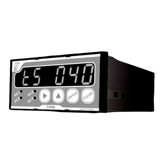
Index Index Index Index TECHNICAL SPECIFICATIONS MECHANICAL MOUNTING ELECTRICAL CONNECTIONS TERMINAL BOARD DESCRIPTION CONNECTION WITH EXTERNALLY POWERED ENCODER CONNECTION WITH SELF-POWERED HALL SENSOR OUTPUTS CONNECTION WITH NPN LOGIC AC OUTPUTS CONNECTION KEYBOARD DESCRIPTION SETUP PROCEDURE WORKING PARAMETERS SETTING WORKING DIAGRAM ERROR MESSAGES WARRANTY... - Page 3 This device allows you to monitor speed of axis motion and to compare this value to two setpoints you can pre-program according to your needs. Every setup setting and work parameter are stored in EEPROM module to guarantee reliability and working assurance. This manual provides all the necessary information for a correct installation and use of this device;...
-
Page 4: Technical Specifications
TECHNICAL SPECIFICAT TECHNICAL SPECIFICATIONS TECHNICAL SPECIFICAT TECHNICAL SPECIFICAT IONS IONS IONS Electrical Specifications Mechanical Specifications 24 – 115 – 230 Vac +/- 10% Self-extinguishing plastic Power supply Container 50/60Hz DIN 48 x 96 x 124 mm Container protection Power consumption 5 VA IP20 degree... -
Page 5: Electrical Connections
ELECTRICAL CONNECTIO ELECTRICAL CONNECTIONS ELECTRICAL CONNECTIO ELECTRICAL CONNECTIO TERMINAL BOARD DESCR TERMINAL BOARD DESCRIPTION IPTION TERMINAL BOARD DESCR TERMINAL BOARD DESCR IPTION IPTION Digital inputs CH A Encoder input: A channel Opto-insulation 2500 V rms CH B Not used Load current 10 mA CH Z Not used... -
Page 6: Outputs Connection With Npn Logic
CONNECTION WITH EXTE CONNECTION WITH EXTE CONNECTION WITH EXTE CONNECTION WITH EXTERNALLY RNALLY RNALLY RNALLY CONNECTION WITH SELF CONNECTION WITH SELF CONNECTION WITH SELF CONNECTION WITH SELF- - - - POWERED POWERED POWERED POWERED POWERED ENCODER POWERED ENCODER HALL SENSOR HALL SENSOR POWERED ENCODER POWERED ENCODER... -
Page 7: Keyboard Description
KEYBOARD DESCRIPTION KEYBOARD DESCRIPTION KEYBOARD DESCRIPTION KEYBOARD DESCRIPTION Normal mode Set-up mode Meaning (if lighted) Start set-up mode; Shift to the right the flashing digit; “OUT 1” output is on (first threshold); Increment flashing digit; “OUT 2” output is on (second threshold); Enter value;... - Page 8 Parameter Function Range and allowed values Notes code Show device code and firmware version Show device code; alternately; Working parameters Active; modification; Inactive; Inactive; Decimal point; from 1 to 5 decimal digit; 00.00÷999.999 1.00 Division ratio; Default = Division ratio = (encoder frequency)/(desired value); 000000 999999 First treshold;...
-
Page 9: Working Parameters Setting
WORKING PARAMETERS S WORKING PARAMETERS S WORKING PARAMETERS S WORKING PARAMETERS SETTING ETTING ETTING ETTING WARNING: these settings are permitted only if is 0 (zero). Description Display Push ; “L00” will flash on the display; Insert desired parameter code and confirm with The value of the chosen parameter will appear;... -
Page 10: Working Diagram
WORKING DIAGRAM WORKING DIAGRAM WORKING DIAGRAM WORKING DIAGRAM Outputs have positive or negative logic, as set in . If these parameters values are 0 or 1, output is activated as soon as measured value gets greater than set threshold and continues to be activated until the measured value gets lower than it (pic. -
Page 11: Error Messages
ERROR MESSAGES ERROR MESSAGES ERROR MESSAGES ERROR MESSAGES Error messages Push and set parameters as has been explained above; EEPROM failure; contact the device reseller; Push and restore setup parameters as explained above; Flashing display measured value exceeds the maximum visualizable value. WARRANT Y WARRANT Y WARRANT Y... - Page 12 Single-axis positioner It shows single-axis level, compares measured value with one setpoint and provides four output signals. Level visualizer It shows single-axis level, with 6 digits visualization, relative counting and two memory records. Frequency meter, speedometer It shows level axis speed, compares it with two setpoints and provides two outputs signals. Counter It shows incremental counting, compares the value with two setpoints and provides two outputs signals.
Need help?
Do you have a question about the TS010 and is the answer not in the manual?
Questions and answers