Table of Contents
Advertisement
Quick Links
Advertisement
Table of Contents

Subscribe to Our Youtube Channel
Related Manuals for Nellcor OxiMax N-550


Summary of Contents for Nellcor OxiMax N-550
- Page 1 N-550 Pulse Oximeter Operator's Manual N-550 /min /min SatSeconds...
- Page 2 To obtain information about a warranty, if any, contact Nellcor’s Technical Services Department, or your local representative. Purchase of this instrument confers no express or implied license under any Nellcor Puritan Bennett patent to use the instrument with any sensor that is not manufactured or licensed by Nellcor Puritan Bennett.
-
Page 3: Table Of Contents
C o n t e n t s Contents ..........i Figures . - Page 4 Contents Setting the Pulse Beep Volume ..........25 Setting the Alarm Volume ............. 26 Setting Alarm Silence Duration ..........26 Disabling Audible Alarms ............28 Verify Patient Settings ............29 Alarm Limits Changed Indicator ..........31 Setting Alarm Limits .............. 31 Setting SatSeconds Duration ..........
- Page 5 Contents Using the Data Port ........51 Overview ................51 Connecting to the Data Port ..........51 Data Port Pinouts ..............52...
- Page 6 Contents Factory Defaults ..............73 SatSeconds Display .............. 75 Describing SatSeconds ............75 SatSeconds “Safety Net” ............77 Principles of Operation ....... . 79 Oximetry Overview ..............
- Page 7 Contents F i g u r e s Figure 1: Front Panel Buttons and Symbols ......5 Figure 2: Rear Panel Symbols ..........6 Figure 3: Real-Time Data Printout ........44 Figure 4: Trend Data Printout ..........45 Figure 5: Data Port Pin Layout ........53 Figure 6: Alarm Response with SatSeconds ....77 Figure 7:...
- Page 8 Contents T a b l e s Table 1: Data Port Pinouts ..........52 Table 2: Sensors by Model Number and Patient Size ... 56 Table 3: Operator’s Menu ..........63 Table 4: Factory Default Settings ........73...
-
Page 9: Safety Information
S a f e t y I n f o r m a t i o n Warnings Warnings are identified by the WARNING symbol shown above. Warnings alert the user to potential serious outcomes (death, injury, or adverse events) to the patient or user. WARNING: Explosion hazard. - Page 10 Safety Information CAUTION: When connecting the N-550 to any instrument, verify proper operation before clinical use. Both the N-550 and the instrument connected to it must be connected to a grounded outlet. Accessory equipment connected to the monitor's data interface must be certified according to IEC Standard 60950 for data-processing equipment or IEC Standard 60601-1 for electromedical equipment.
-
Page 11: Introduction
Use with any particular patient requires the selection of an appropriate oxygen transducer (sensor) as described in this Operator's Manual. Motion performance claims are applicable to models MAX-A, MAX-AL, MAX-P, MAX-N, and MAX-I Nellcor O oximetry sensors. N-550... - Page 12 (Blank Page)
-
Page 13: Description Of Controls, Indicators, And Symbols
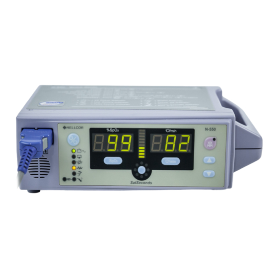
D e s c r i p t i o n o f C o n t r o l s , I n d i c a t o r s , a n d S y m b o l s Identification of Front Panel Buttons and Symbols Figure 1: Front Panel Buttons and Symbols 1. -
Page 14: Identification Of Rear Panel Components
Description of Controls, Indicators, and Symbols Identification of Rear Panel Components 1. Data Port Connector 3. AC Power Connector 2. Foot Switch Connector 4. Equipotential Connector (ground) Figure 2: Rear Panel Symbols... -
Page 15: 550 Symbols
Description of Controls, Indicators, and Symbols 550 Symbols The symbols that are located on the rear panel of the N-550 are as follows: 1. Data Interface 3. Foot Switch 2. Caution - Do not connect while 4. Equipotential Terminal power is on (ground) The symbols that are located on the front panel of the N-550 are as follows:... -
Page 16: Description Of Controls
Description of Controls, Indicators, and Symbols Description of Controls The Power On/Off button is used to turn the N-550 monitor on or off. Note: Each button press, except the Power On/Off button, should result in either a valid or an invalid button tone. If the button pressed fails to emit a tone, contact qualified service personnel. -
Page 17: Description Of Displays And Indicators
Description of Controls, Indicators, and Symbols The SatSeconds Alarm Limit button is used to view the SatSeconds alarm limit. When pressed the menu options are enabled. The Adjust Up and Adjust Down buttons are used to change the SatSeconds limit settings. - Page 18 Description of Controls, Indicators, and Symbols The Alarm Silence Indicator. Lights continuously when an audible alarm has been silenced. It flashes when the alarm silence duration has been set to OFF. ® The Motion Indicator. Lights continuously whenever the OxiSmart XL algorithm detects the presence of artifact independent of its severity or the impact on the SpO or pulse rate values.
-
Page 19: Description Of Audible Indicators
Description of Controls, Indicators, and Symbols The SatSeconds Indicator. Fills in clockwise as the SatSeconds alarm management approaches the SatSeconds alarm limit threshold. When a SatSeconds setting other than OFF is selected, the green LED at the top of the SatSeconds indicator will light. The green LED at the 12-o'clock position indicates that SatSeconds are engaged. - Page 20 Description of Controls, Indicators, and Symbols Confirmation Tone Three beeps sound to indicate that default settings have been saved or reset to factory defaults or trend data has been deleted...
-
Page 21: Setting Up The Monitor
WARNING: As with all medical equipment, carefully route patient cabling to reduce the possibility of patient entanglement or strangulation. WARNING: Disconnect the N-550 and Nellcor sensor from the patient during magnetic resonance imaging (MRI) scanning. Induced current could potentially cause burns. The N-550 may affect the MRI image;... -
Page 22: List Of Components
N-550 monitor. Use of another sensor cable will have an adverse effect on performance. Do not attach any cable that is intended for computer use to the sensor port. Do not connect any device other than a Nellcor-approved sensor to the sensor connector. List of Components 1 N-550 Pulse Oximeter... -
Page 23: Connecting The N-550 To Ac Power
Setting up the Monitor Connecting the N 550 to AC Power 1. Power Connector 1. Plug the female connector of the power cord into the monitor AC power connector (1). 2. Plug the male connector of the power cord into a properly grounded AC outlet. -
Page 24: Connecting A Sensor To The N-550
N-550 monitor. Use of another sensor cable will have an adverse effect on performance. Do not attach any cable that is intended for computer use to the sensor port. Do not connect any device other than a Nellcor-approved sensor to the sensor connector. 1. SpO Sensor Port 1. -
Page 25: Battery Operation
B a t t e r y O p e r a t i o n WARNING: Dispose of an old battery by following local guidelines for disposal of lead acid batteries. Operating the N 550 on Battery Power The N-550 has an internal battery that may be used to power the monitor during transport or when AC power is not available. -
Page 26: Low Battery Indicator
Battery Operation Low Battery Indicator The Low Battery Indicator lights and a low priority alarm begins to sound when approximately 15 minutes of monitoring time remain on the existing battery charge. This alarm cannot be silenced while running on battery power. Connecting the monitor to AC power will silence the alarm. -
Page 27: Using The Monitor
CAUTION: If any indicator or display element does not light, or the speaker does not sound, do not use the monitor. Instead, contact qualified service personnel, your local Nellcor representative, or Nellcor's Technical Services Department, 1.800.635.5267. - Page 28 Using the Monitor 3. The monitor automatically starts the Power-On Self-Test (POST), which tests monitor circuitry and functions. CAUTION: During POST (immediately after power-up), confirm that all display segments and indicators light, and the speaker sounds a 1-second pass tone. 4.
- Page 29 Device version numbers are often needed when calling Nellcor's Technical Services Department, 1.800.635.5267, or your local Nellcor representative for technical assistance. Write down the numbers and have them available prior to requesting technical assistance. 6. If the N-550 detects an internal problem during the self-test, an alarm tone sounds and the monitor displays an Error Code and the corresponding number.
-
Page 30: Sensor Attached
Using the Monitor Note: In addition to serving as the POST pass verification, the POST pass tone also functions as an audible confirmation that the speaker is performing properly. If the speaker does not function, the alarm sounds cannot be heard. Sensor Attached The Pulse Search indicator and the Sensor Off indicator light and the monitor displays dashes in the %SpO... -
Page 31: No Sensor Attached
Using the Monitor No Sensor Attached When the sensor is not attached the monitor displays dashes (---) and the Pulse Search indicator is not lit, indicating that the monitor failed to detect a sensor. N-550... -
Page 32: Sensor Message
Using the Monitor Sensor Message The Sensor Message feature is an indication that the sensor position or site needs to be considered. The Sensor Message indicator lights when the monitor cannot determine an SpO level or a pulse rate. The Sensor Message recommendations for improving the signal are: •... -
Page 33: Setting The Pulse Beep Volume
Using the Monitor Setting the Pulse Beep Volume 1. SpO Sensor Port WARNING: Use only Nellcor-approved sensors and sensor cables. 1. Connect a DOC-10 pulse oximetry cable to the SpO Sensor Port (1) on the front of the monitor. 2. Connect an SpO Sensor to the other end of the DOC-10 pulse oximetry cable. -
Page 34: Setting The Alarm Volume
Using the Monitor Setting the Alarm Volume With the monitor in the normal monitoring mode: 1. Press and hold the Alarm Silence button until the alarm volume display appears. 2. While continuing to press the Alarm Silence button, press the Adjust Up button or Adjust Down button to increase or decrease the alarm volume. - Page 35 Using the Monitor Visual indications of an alarm condition cannot be turned off. For example, if the %SpO lower alarm limit is exceeded, the alarm can be silenced for the alarm silence duration, but the %SpO value will continue to flash. If the alarm condition is still present when the alarm silence duration has elapsed, the alarm will sound.
-
Page 36: Disabling Audible Alarms
Using the Monitor Disabling Audible Alarms Setting the alarm silence duration to OFF means that the monitor will produce no audible alarms. Visual indications of an alarm condition are not affected by disabling the audible alarms. The ability to set the alarm silence duration to OFF can be enabled or disabled by qualified service personnel as described in the service manual. -
Page 37: Verify Patient Settings
Using the Monitor 3. The Alarm Silence indicator will flash, indicating that the alarm sounds are disabled. The monitor will sound three beeps approximately every three minutes to warn the user that the alarm sound has been silenced. Verify Patient Settings With the monitor in the normal monitoring mode: 1. - Page 38 Using the Monitor 3. Press the Pulse Rate Alarm Limit button to view the current Pulse Rate upper alarm limit. 4. Press the Pulse Rate Alarm Limit button twice to view the current Pulse Rate lower alarm limit. 5. Press the SatSeconds Alarm Limit button to view the current SatSeconds setting.
-
Page 39: Alarm Limits Changed Indicator
Using the Monitor Alarm Limits Changed Indicator If an alarm limit is changed from the N-550’s power-on default setting, a decimal point appears after the applicable displayed value, during patient monitoring and when alarm limits are viewed. The decimal point remains on the display until the N-550 is turned off or the limit is returned to the default value. - Page 40 Using the Monitor 2. Press the Adjust Up button or Adjust Down button to increase or decrease the alarm limit setting. Note: When an alarm limit is changed from power-on default, the N-550 displays a decimal point (.) after the changed parameter. 3.
-
Page 41: Setting Satseconds Duration
Using the Monitor 6. Press the Adjust Up button or Adjust Down button to increase or decrease the alarm limit setting. 7. Press the Pulse Rate Alarm Limit button twice to view the current lower alarm limit for Pulse Rate. 8. -
Page 42: Setting The Data Port Baud Rate
Using the Monitor Note: The possible settings for SatSeconds are Off, 10, 25, 50, and 100 seconds. 2. Press the Adjust Up button or Adjust Down button to select the desired SatSeconds setting. Setting the Data Port Baud Rate The baud rate determines the speed at which the N-550 sends data to the attached equipment (printer or portable computer). -
Page 43: Setting The Data Port Protocol
Using the Monitor 3. Press the SatSeconds Alarm Limit button. Current baud rate is displayed. 4. Press the Adjust Up button or Adjust Down button to select the desired baud rate. Possible settings are 24 (2,400), 96 (9,600) and 192 default (19,200). Setting the Data Port Protocol With the monitor in the normal monitoring mode: 1. -
Page 44: Clearing Trend Information
Using the Monitor 3. Press the SatSeconds Alarm Limit button. Current protocol is displayed. 4. Press the Adjust Up button or Adjust Down button to select the desired protocol. Possible settings are: • 1 - ASCII • 2 - External equipment communications. Refer to the external equipment manuals for the interfacing instructions. - Page 45 Using the Monitor 2. Press the Adjust Up button to select Option 2. 3. Press the SatSeconds Alarm Limit button to clear the trend data. 4. The monitor emits 3 beeps, indicating that data is cleared. N-550...
- Page 46 (Blank Page)
-
Page 47: Monitor Trend
M o n i t o r T r e n d Trend Data Operation From the initial measurement of a patient, trend data (a data point) is stored in memory every 4 seconds. Up to 50 alarm limit changes can also be stored in trend data. -
Page 48: Trend Data
Monitor Trend Trend Data Trend data information may be retrieved or cleared through the N-550 data port using options available in a display menu. To access the menu options, simultaneously press the SpO Alarm Limit and Pulse Rate Alarm Limit buttons until Option 1 appears on the display. -
Page 49: 4: Baud Rate
Monitor Trend #4: Baud Rate Allows the interconnection to various printers. Refer to Setting the Data Port Baud Rate on page 34. The baud rate selections are: • 24 (2,400 baud rate) • 96 (9,600 baud rate) • 192 default (19,200 baud rate) #5: Data Port Printout Selections are as follows: Option 1... - Page 50 (Blank Page)
-
Page 51: Printing
P r i n t i n g Printing Monitor Real-Time Data Real-time data is continuously sent to the data port on the back of the N-550. Patient data can be obtained through the data port by connecting to a computer or serial printer. When a real-time printout or display is being transmitted to a printer or computer, a new line is printed/displayed every 2 seconds. -
Page 52: Figure 3: Real-Time Data Printout
Printing 2. Turn on the printer. 3. Connect the N-550 to an AC outlet. 4. Turn on the N-550. The printer will start printing real time trend data or the PC will start displaying real time data at a rate of one line every 2 seconds. Figure 3: Real-Time Data Printout... -
Page 53: Trend Data Printout
Printing Trend Data Printout The format of data displayed when a trend printout is requested is the same as the real-time data. The only differences are that “TREND” is displayed in the top row instead of the “CRC: XXXX” software verification number and there is no “Status”... -
Page 54: Column Headings
Printing Column Headings Column headings are displayed or printed after every 25 lines, or if one of the values in the column heading changes. Data Source Data in the highlighted box above represents the model number of the monitor, in this case the N-550. Device/Software Revision Level The next data field tells the user the software level (Version 1.00.00) and a software verification number (CRC: XXXX). -
Page 55: Alarm Limits
Printing Alarm Limits The last data field in the top line indicates the upper and lower alarm limits for %SpO and for the pulse rate (PR), and the SatSeconds alarm setting (OFF). The SatSeconds setting may be OFF, 10, 25, 50, or 100 depending on the SatSeconds alarm setting. -
Page 56: Time
Printing Time The Time column represents the N-550 real-time clock. Refer to the N-550 service manual to set the N-550 real-time clock. Patient Data Patient data is highlighted in the display above. Parameter values are displayed directly beneath the heading for each parameter. In this example, the %SpO is 100, and the pulse rate is 190 beats per minute. - Page 57 Printing The Status column indicates alarm conditions and operating status of the N-550. In this example, Pulse High (PH) means that the pulse rate upper alarm limit has been exceeded. The status codes are listed below. As many as four codes can be displayed at one time in the Status column.
- Page 58 (Blank Page)
-
Page 59: Using The Data Port
U s i n g t h e D a t a P o r t Overview Patient data can be obtained through the data port on the back of the N-550 by connecting it to an attached PC or serial printer. When connecting the N-550 to a printer or PC, verify proper operation before clinical use. -
Page 60: Data Port Pinouts
Using the Data Port Data Port Pinouts The pinouts for the data port are listed in Table 1. Table 1: Data Port Pinouts Signal Name Not connected RxD_232 (RS-232 input) TxD_232 (RS-232 output) Not connected Signal Ground (isolated from Earth Ground) Not connected Not connected Not connected... -
Page 61: Figure 5: Data Port Pin Layout
Using the Data Port Figure 5: Data Port Pin Layout Pins 2, 3, and 5 provide data in RS-232 format. No hardware flow control is used. N-550... - Page 62 (Blank Page)
-
Page 63: Sensors And Accessories
WARNING: Do not use a damaged sensor or pulse oximetry cable. Do not use a sensor with exposed optical components. WARNING: Use only Nellcor sensors and pulse oximetry cables with this monitor. Other sensors or pulse oximetry cables may cause improper N-550 performance. -
Page 64: Table 2: Sensors By Model Number And Patient Size
For more information, refer to Table 2 or contact your local Nellcor representative. For a complete and up-to-date listing of all sensors applicable to the N-550, refer to the Sensor Accuracy Grid posted on the Internet at: http://www.mallinckrodt.com/respiratory/resp/Serv_Supp/ProductManuals.html... -
Page 65: Biocompatibility Testing
(Reusable, nonsterile) Biocompatibility Testing Biocompatibility testing has been conducted on Nellcor sensors in compliance with ISO 10993-1, Biological Evaluation of Medical Devices, Part 1: Evaluation and Testing. The sensors have passed the recommended biocompatibility testing and are therefore in compliance with ISO 10993-1. -
Page 66: Foot Switch
Sensors and Accessories Foot Switch An optional foot switch is available for the N-550. The foot switch may be used to silence N-550 alarms. The foot switch is connected to the rear of the N-550. CAUTION: The N-550 must be turned off when connecting or disconnecting the foot switch. -
Page 67: N-550 Performance Considerations
P e r f o r m a n c e C o n s i d e r a t i o n s WARNING: Pulse oximetry readings and pulse signals can be affected by certain ambient environmental conditions, sensor application errors, and certain patient conditions. -
Page 68: Dysfunctional Hemoglobins
Performance Considerations Dysfunctional Hemoglobins Dysfunctional hemoglobins such as carboxyhemoglobin, methemoglobin, and sulphemoglobin are unable to carry oxygen. readings may appear normal; however, a patient may be hypoxic because less hemoglobin is available to carry oxygen. Further assessment beyond pulse oximetry is recommended. Anemia Anemia causes decreased arterial oxygen content. - Page 69 • there is arterial occlusion proximal to the sensor Use only Nellcor sensors and sensor cables. WARNING: The use of accessories, sensors, and cables other than those specified may result in increased emission and/or decreased immunity and inaccurate readings of the N-595 pulse oximeter.
- Page 70 Performance Considerations If patient movement presents a problem, try one or more of the following remedies to correct the problem. • verify that the sensor is properly and securely applied • move the sensor to a less active site • use an adhesive sensor that tolerates some patient motion •...
-
Page 71: Operator's Menu
O p e r a t o r ’s M e n u This operator’s menu provides a quick reference to the functions on the monitor. Table 3: Operator’s Menu Sub- Reference Menu Function Menu Paragraph Trend print (tabular Trend Data Printout monitor trend only) on page 45 Trend clear... - Page 72 (Blank Page)
-
Page 73: Troubleshooting
If you experience a problem while using the N-550 and are unable to correct it, contact Nellcor’s Technical Services Department or your local Nellcor representative. The N-550 service manual, which is for use by qualified service personnel, provides additional troubleshooting information. - Page 74 2. One or more display segments or indicators do not light during the power-on self-test. • Do not use the N-550; contact qualified service personnel or your local Nellcor representative. 3. The monitor does not sound a tone indicating successful completion of the Power-On Self-Test (POST). •...
- Page 75 Troubleshooting • Excessive patient motion may be preventing the N-550 from tracking the pulse. Keep the patient still, if possible. Verify that the sensor is securely applied, and replace it if necessary. Change the sensor site. Use a type of sensor that tolerates more patient movement (for example, an adhesive sensor).
-
Page 76: Emi (Electro-Magnetic Interference)
If the display shows the error code once again, record the number and provide that information to qualified service personnel, or your local Nellcor representative. •... -
Page 77: Obtaining Technical Assistance
N-550. When calling Nellcor’s Technical Services Department, 1.800.635.5267, or your local Nellcor representative, you may be asked to tell the representative the software version number of your N-550. - Page 78 (Blank Page)
-
Page 79: Maintenance
Returning the N-550 Contact Nellcor’s Technical Services Department, 1.800.635.5267, or your local Nellcor representative for shipping instructions including a Returned Goods Authorization (RGA) number. Unless otherwise instructed by Nellcor’s Technical Services Department, it is not necessary to return the sensor or other accessory items with the monitor. -
Page 80: Periodic Safety Checks
Maintenance Periodic Safety Checks It is recommended that the following checks be performed every 24 months. • Inspect the equipment for mechanical and functional damage. • Inspect the safety-relevant labels for legibility. Cleaning CAUTION: Do not spray, pour, or spill any liquid on the N-550, its accessories, connectors, switches, or openings in the chassis. -
Page 81: Technical Information
T e c h n i c a l I n f o r m a t i o n Description of Alarms The N-550 has three levels of audible alarms. 1. High-priority alarm: A high-pitched, fast-pulsating tone indicating loss of pulse with no patient motion. 2. - Page 82 Technical Information Table 4: Factory Default Settings Factory Parameter Range Default Setting Pulse Rate Upper Lower Alarm Limit 170 BPM Alarm Limit plus 1 to 250 BPM Pulse Rate Lower 30 BPM to Upper 40 beats per Alarm Limit Alarm Limit minus 1 minute (BPM) Alarm Silence On or Off...
-
Page 83: Satseconds Display
Technical Information Table 4: Factory Default Settings Factory Parameter Range Default Setting Language English English Pulse Beep Volume 0 to 10 SatSeconds Off, 10, 25, 50, 100 SatSeconds Display When the N-550 SatSeconds technology detects an SpO value outside the alarm limit, the SatSeconds indicator LEDs begin to light (fill) clockwise. - Page 84 Technical Information The N-550 utilizes Nellcor SatSeconds alarm management. With the SatSeconds technique, upper and lower alarm limits are set in the same way as traditional alarm management. However, the clinician also sets a SatSeconds limit that allows monitoring of %SpO...
-
Page 85: Satseconds "Safety Net
Technical Information Figure 6: Alarm Response with SatSeconds Saturation levels may fluctuate rather than remaining steady for a period of several seconds. Often, %SpO levels may fluctuate above and below the alarm limit, re-entering the non-alarm range several times. During such fluctuation, the N-550 integrates the number of %SpO points, both positive and negative, until either the SatSeconds limit (SatSeconds setting) is reached, or the %SpO level returns within a... - Page 86 (Blank Page)
-
Page 87: Principles Of Operation
P r i n c i p l e s o f O p e r a t i o n Oximetry Overview The N-550 uses pulse oximetry to measure functional oxygen saturation in the blood. Pulse oximetry works by applying a sensor to a pulsating arteriolar vascular bed, such as a finger or toe. -
Page 88: Automatic Calibration
Principles of Operation difference between maximum and minimum absorption (measurements at systole and diastole). By doing so, it focuses on light absorption by pulsatile arterial blood, eliminating the effects of nonpulsatile absorbers such as tissue, bone, and venous blood. There are various matrixes within the OxiSmart XL algorithm. Some are used to assess the severity of conditions presented to the N-550 in measuring SpO and pulse rate. -
Page 89: Functional Versus Fractional Saturation
Principles of Operation Functional versus Fractional Saturation This monitor measures functional saturation -- oxygenated hemoglobin expressed as a percentage of the hemoglobin that can transport oxygen. It does not detect significant amounts of dysfunctional hemoglobin, such as carboxyhemoglobin or methemoglobin. In contrast, hemoximeters such as the IL482 report fractional saturation -- oxygenated hemoglobin expressed as a percentage of all measured hemoglobin, including measured dysfunctional hemoglobins. -
Page 90: Figure 7: Oxyhemoglobin Dissociation Curve
Principles of Operation Figure 7: Oxyhemoglobin Dissociation Curve... -
Page 91: Specifications
S p e c i f i c a t i o n s Performance Measurement Range 1% to 100% Pulse Rate 0 and 20 beats per minute (BPM) to 250 BPM Perfusion Range 0.03% to 20% Accuracy and Motion Tolerance Saturation 70 to 100% ±2 digits Without Motion - Adults... -
Page 92: Electrical
Specifications Accuracy and Motion Tolerance Adult specifications are shown for O MAX-A and MAX-N sensors with the N-550. Neonate specifications are shown for MAX-N sensors with the N-550. Saturation accuracy will vary by sensor type. Refer to the Sensor Accuracy Grid. Applicability: O MAX-A, MAX-AL, MAX-P, MAX-I, and MAX-N sensors. -
Page 93: Environmental Conditions
Specifications Sensors Wavelength The wavelength range of the light emitted are and Power near 660 nm and 890 nm with the energy not exceeding 15 mW. Environmental Conditions Operation Temperature 10 ºC to 45 ºC (50 ºF to 113 ºF) Altitude -390 m to 3,012 m (-1,254 ft. - Page 94 Specifications Transport and Storage (in shipping container) Barometric Pressure 50 kPa to 106 kPa (14.7 in. Hg to 31.3 in. Hg) Relative Humidity 15% to 95% non-condensing Sensor Power Dissipation Sensor Dissipation MAX-N 52.5 mW MAX-I 52.5 mW MAX-P 52.5 mW MAX-A 52.5 mW MAX-AL...
-
Page 95: Physical Characteristics
Specifications Physical Characteristics Weight 3.07 lbs. (1.39 kg) without pole mount Dimensions 2.87 in. x 7.87 in. x 5 in. (7.3 cm x 20 cm x 12.7cm) Compliance Item Compliant With Equipment classification Safety Standards: IEC 60601-1 (same as EN60601-1), EN865, EN/IEC 60601-1-2:1993, CAN/CAS C22.2 No. - Page 96 Specifications Item Compliant With External case made with IEC 60601-1, sub-clause 16(a) non-conductive plastic No holes in case top IEC 60601-1, sub-clause 16(b) Rigid case IEC 60601-1, sub-clause 21(a) Case mechanically strong IEC 60601-1, sub-clause 21(b) Case handle IEC 60601-1, sub-clause 21(c) N-550 resistant to rough IEC 60601-1, sub-clause 21.6 handling...
-
Page 97: Table
Specifications Item Compliant With Electromagnetic IEC 60601-1, sub clause 36, IEC/EN Compatibility 60601-1-2 (second edition) Radiated and conducted EN 55011, Group 1, Class B emissions Harmonic emissions IEC 61000-3-2 Voltage fluctuations/ IEC 61000-3-3 flicker emissions Electrostatic discharge EN 61000-4-2, level 3 table top immunity equipment Radiated radio-frequency... - Page 98 (Blank Page)
-
Page 99: Index
I n d e x Symbols Connecting a Sensor Connecting to the Data Port %SpO2 Display Corrective Action AC Power Indicator Data Port Pinouts Adjust Down Button Data Port Printout, Option 0 Adjust Up Button Data Port, Connecting to Alarm Limits, Setting Decimal Point Alarm Off Default, Factory... - Page 100 Index Measured Saturation Rear Panel Returning the N-550 Monitor Accuracy and Motion Tolerance 83 Safety Checks Measurement Range 83 Safety Information Motion Indicator SatSeconds Duration, Setting Saturation High Limit Alarm Saturation Low Limit Alarm N-550 Returning Saturation, Calculated Saturation, Fractional Saturation, Measured Operating Relative Humidity 85...
- Page 101 Index Technical Assistance Transport Relative Humidity 85 Temperature 85 Trend Clear Trend Data Operation Trend Print N-550...
- Page 102 (Blank Page)
- Page 103 (Blank Page)
- Page 104 Nellcor Puritan Bennett Division 4280 Hacienda Drive Pleasanton, CA 94588 U.S.A. Telephone Toll Free 1.800.563.5267 Authorized Representative Tyco Healthcare UK LTD 154 Fareham Road Gosport PO13 0AS, U.K. Rx ONLY © 2002 Nellcor Puritan Bennett Inc. All rights reserved. 066865A-0802...
Need help?
Do you have a question about the OxiMax N-550 and is the answer not in the manual?
Questions and answers