Advertisement
Quick Links
Please read all instructional literature carefully and thoroughly before starting. Refer to the final page for the listing of Recommended
Practices, Liabilities and Warranties.
GENERAL
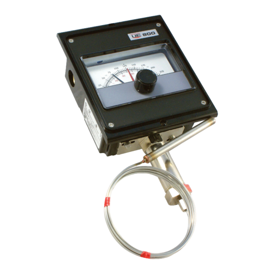
Temperature variations are sensed by a liquid filled sensing bulb which
hydraulically transmits motion through a mechanism which rotates the indi-
cating pointer and actuates precision snap-acting switch(es). Control set
point(s) are varied by turning the external adjustment knob(s), according to
procedures outlined (See Part II - Adjustments). Thermometer type T800
provides temperature indication only with no snap-acting switch.
MAXIMUM TEMPERATURE* STATED IN LITERATURE AND ON
NAMEPLATE MUST NEVER BE EXCEEDED, EVEN BY SURGES IN
THE SYSTEM. OCCASIONAL OPERATION OF UNIT UP TO MAX.
TEMPERATURE IS ACCEPTABLE (E.G., START-UP, TESTING). CONTINUOUS
OPERATION SHOULD BE RESTRICTED TO THE DESIGNATED ADJUSTABLE
RANGE.
Maximum Temperature - the highest temperature to which a sensing element
may be occasionally operated at, without adversely affecting set point calibra-
tion and repeatability.
Please refer to product bulletins for product specifications. Product bulletins
may be found at www.ueonline.com.
Part I -Installation
INSTALL UNIT WHERE SHOCk, VIBRATION AND TEMPERATURE FLUC-
TUATIONS ARE MINIMAL. DO NOT MOUNT UNIT IN AMBIENT TEMPERA-
TURES EXCEEDING PUBLISHED LIMITS. ORIENT UNIT SO THAT MOIS-
TURE IS PREVENTED FROM ENTERING THE ENCLOSURE.
PREVENTATIVE MAINTENANCE / PERIODIC TESTING (6 MONTHS OR SOONER
AS DICTATED BY THE ENVIRONMENT) IS NECESSARY TO ENSURE OPERATION
OF THE PRODUCT TO SPECIFICATION. LUBRICATE ALL PIVOT POINTS AND
MOVING PARTS, TO PREVENT CORROSION, WITH COMPATIBLE DRY LUBRICANTS OR LIGHT
GREASE.
When mounting 800 or 802 type controls, it may be necessary to remove
adjustment knob and front cover. The knob is secured with a 5/64" Allen
Setscrew. The cover is secured by four phillips screws at the corners.
MouNTING
The controller may be mounted in any position to either a surface or panel
800 Series
Indicating Temperature Controls
Types 800, T800, 802
Please refer to IMT120 for Explosion Proof Types
820E and 822E
Tools Needed
Phillips screwdriver to secure
customer supplied screws
5/64" Allen Wrench
www.ueonline.com
U N I T E D E L E C T R I C
C O N T R O L S
Installation and Maintenance
Instructions
(1/4" thick maximum). Locate it where vibration, shock and ambient tempera-
ture fluctuations are minimal. It is recommended that mounting the unit with
the conduit connection on the top be avoided.
To Flush Mount
Cut out the panel as shown in Figure 1A. Mount to the panel using the two
holes located on the flange of the enclosure.
To Surface Mount
Attach 2 mounting ears found in separate package to recessed areas on
back side of enclosure by means of 2 self-tapping screws. Mount to surface
per Figure 1B.
Clearance for #10
screw - (2) places
Mounting Bulb and Capillary
Fully immerse the bulb and 6" of capillary in the control zone. For best con-
trol it is generally desirable to place the bulb close to the heating or cooling
source in order to sense temperature fluctuations quickly. Be sure to locate
the bulb so it will not be exposed to temperature beyond the instruments
range limits.
Try to place any remaining capillary adjacent to the control head so it will
sense the same ambient temperatures (control is ambient temperature com-
pensated).
Unless otherwise specified, factory calibration, allows for 6" of capillary tube
in the control zone. If longer lengths are required recalibration may be nec-
essary. Follow the procedure outlined in PART II - Adjustments.
Avoid bending or coiling the capillary tube tighter than 1/2" radius.
Exercise caution when making bends near the capillary ends.
If a separable well or union connector is used follow separate instructions
included with them.
IM800-06
CLEARANCE FOR #8
SCREW - (2) PLACES
Figure 1A -
Flush Mounting
Figure 1B -
Surface Mounting
IM800-06
Advertisement

Related Manuals for UE 800 Series

Summary of Contents for UE 800 Series
-
Page 1: Installation And Maintenance
IM800-06 800 Series Indicating Temperature Controls U N I T E D E L E C T R I C Types 800, T800, 802 C O N T R O L S Please refer to IMT120 for Explosion Proof Types... - Page 2 WIRING Part II - Adjustments Tools Needed (Refer to Figure 3) DISCONNECT ALL SUPPLY CIRCUITS BEFORE WIRING. ELECTRICAL RATINGS STATED IN LITERATURE AND ON NAMEPLATE SHOULD 5/64” Allen Wrench NEVER BE EXCEEDED. OVERLOAD ON A SWITCH CAN CAUSE FAILURE 5/16” Open End Wrench (2 required) ON THE FIRST CYCLE.
- Page 3 General Layout Adjusting Thermometer Type T800 Use the in-process adjustment to check the control. Differences between the test instrument and the thermometer can be corrected by turning the zero adjustment “C” per Figure 3 on the thermal assembly. Turning in lowers SWITCH 1 indicated reading.
- Page 4 RECoMMENDED PRACTICES AND WARNINGS United Electric Controls Company recommends careful consideration of the following factors when specifying and installing UE pressure and temperature units. Before installing a unit, the Installation and Maintenance instructions provided with unit must be read and understood.
Need help?
Do you have a question about the 800 Series and is the answer not in the manual?
Questions and answers